Galvanizing, a coating of zinc has been used to protect iron and steel from rusting or corrosion. Galvanized steel, due to its high durability is used widely worldwide. Even though it is always suggested to avoid welding on galvanized steel due to the generation of hazardous fumes, they can be welded like normal steel using similar welding techniques. But, proper care must be exercised to protect the welding personnel during the galvanized steel welding process. Common welding techniques for galvanized steel are gas metal arc, carbon arc, gas tungsten arc, manual metal arc, and torch welding. In this article, we will find out more details about the welding of galvanized steel.
Personal Protection for Welding Galvanized Steel
The zinc coating of the galvanized steel easily vaporizes at a high temperature during the welding process. This creates zinc oxide fumes that can cause a short-term health effect known as metal fume fever or galvanized poisoning. Galvanized poisoning is characterized by flu-like symptoms including nausea, headaches, high fever, shivers, and thirst. Also, a small amount of lead that may be present on galvanized coating can lead to the generation of lead oxide fumes. These fumes have long-term health hazards like lung or brain cancer and complications in the nervous system.
It is, therefore, first and foremost to use proper welding protective equipment when welding galvanized steel. The welder must wear high-quality welding helmets, gloves, leather jackets, steel toe boots, and respirators. The respirator during welding galvanized steel ensures that the zinc and lead oxide fumes are not inhaled. The welder must be well-trained for welding galvanized steel and the welding must be performed in a well-ventilated area to maximize clean airflow.
Preparing to Weld Galvanized Steel
The first step in welding galvanized steel is to adequately prepare it for welding. The galvanizing layer near the weld region (at least 2 to 4 inches from either side) must be removed first by grinding or other methods. Other methods of removing zinc coating are by burning with a carbon arc or an acetylene torch while using an oxidizing flame, or by shot blasting with portable equipment. So, the welding can easily be performed now like uncoated carbon steel. Once the welding operation is complete, the protective coating must be restored to get proper corrosion resistance. ASTM A780 or similar other standards can be used for restoring the zinc protective layer after welding galvanized steel.
When the galvanized coating is not removed, the weld should be made using the galvanized base metal with the thickest coating anticipated and qualified by test following AWS D1.1 or AWS D1.4. These Welding Procedure Specifications (WPS) will permit welding over surfaces with zinc coatings equal to or less than the coating used in qualification testing. In general, to avoid zinc penetration of the welds, the procedure should involve greater
root openings in joints, electrodes with low silicon content, and slower welding speeds.
Galvanized Steel Welding by Gas Metal Arc Welding
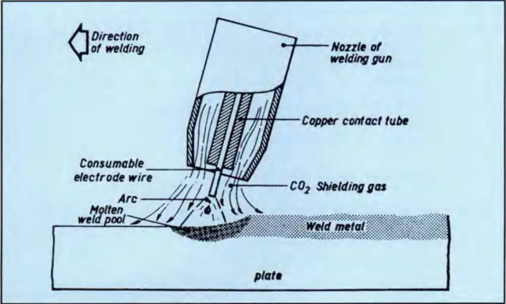
Gas metal arc (GMA) welding, or Metal-Inert Gas (MIG) welding, is a versatile semi-automatic welding process that is easily and conveniently used for welding galvanized steel of thinner materials. Fig. 1 below shows a typical illustration of the GMA welding process. In the GMA welding of galvanized steel, the zinc coating does not affect weld mechanical properties, other than some appearance changes due to weld spatter. Excellent Arc stability is achieved which is generally unaffected by the galvanized coating. However, Some reduction in welding speed is required.
A protective gas shield is used. Carbon dioxide is the cheapest and most widely used shielding gas for welding uncoated galvanized steel. However, due to its superior surface appearance, weld bead shape, and reduced spatter, a more expensive shielding gas, comprising 75% argon and 25% CO2, is sometimes preferred for welding uncoated mild steel. For welding galvanized steel, less expensive CO2 may be satisfactorily used. However, most welding shops normally use an argon-CO2 mixture for galvanized material.
To allow time for the galvanized coating to burn off at the front of the weld pool GMA welding speeds should be slower. The welding speed reduction relates to the zinc coating thickness, the joint type, and the welding position. By increasing the current, steels with thicker galvanized coatings may be fillet welded more readily. The increased heat input is required to burn away the extra zinc at the front of the weld pool.
Penetration of the weld in zinc-coated steels is less than for uncoated steels. A slightly wider gap, therefore, must be provided for butt welds. While making butt weld in a flat position, a slight side-to-side movement of the welding torch helps achieve consistent penetration.
Spatter increases when welding galvanized steel using both CO2 and an argon-CO2 mixture shielding gas. Spatter particles that adhere to the workpiece can cause an unsightly appearance. By applying silicone, petroleum, or graphite-based spatter release compounds to the workpiece before welding, this can be avoided. Spatter particles are then removed by brushing. However, a build-up of spatter in the nozzle of the welding gun may be encountered. The application of an anti-spatter compound will reduce the particles trapped by the welding nozzle.
With an increase in the zinc coating thickness, the spatter formation increases and is, therefore, greater on batch-galvanized materials than on continuously coated sheet materials. Spatter particles tend to roll into the corner of the joint when tee joints in batch galvanized steel are welded in the flat position, causing difficulty in welding. While welding in the overhead position, the spatter may fall into the nozzle of the welding gun.
The higher heat input to remove the zinc from the weld pool and slower welding speeds to burn off the zinc coating are what differentiate the GMA welding process between welding zinc-coated steel and uncoated steel. Using a shielding gas of argon and carbon dioxide can give a more stable arc and produce smoother weld deposits with minimum spatter and zinc loss.
Welding Galvanized Steel by SMAW & MMAW
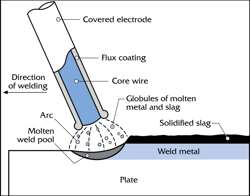
Both Shielded Metal Arc Welding (SMAW) and Manual Metal Arc Welding (MMAW) for welding galvanized steel are manual processes using flux-covered electrodes of 1.6 mm to 12.7 mm in diameter. The welding conditions necessary for galvanized steel welding by SMAW and MMAW are similar to those used on uncoated steel. However, the welding speed needs to be slower because the angle of the electrode is reduced to about 30º and a whipping motion of the electrode back and forth is needed to move the molten zinc pool away from the weld.
The major difference between welding zinc-coated steel (galvanized steel) and welding uncoated steel using the SMAW process is that the root opening must be increased to give full weld penetration. In the SMAW process, the amount of spatter is slightly higher as compared to welding on uncoated steel. The conditions for the root pass in butt-welds on batch galvanized steel by SMAW process are available in AWS D19.0, Tables 6.2 through 6.5.
MMAW is used for galvanized steels of 12.7 mm thickness or greater. In general, welders can use the same procedures for welding galvanized steel as for uncoated steel. However, the following points must be kept in mind:
- The electrode speed applied should be lower than normal. A whipping action by moving the electrode forward along the seam in the direction of the weld and then back into the molten zinc pool must be provided.
- Weaving and multiple weld beads should be avoided, as should excessive heat injection into the joint that may damage the adjacent zinc coating.
- To give better control of the weld pool and to prevent either intermittent excessive penetration or undercutting a short arc length is recommended for all positions.
- For butt welding, slightly wider gaps are required to have complete penetration.
- To achieve better welding quality, grinding off edges before welding is suggested. It also will reduce the fuming from the galvanized coating. Further welding procedures will then be the same as for uncoated steel.
Welding Galvanized Steel with Other Metals
Galvanized steel can be welded to other metals, including stainless steel, using the above-mentioned techniques. To get quality welding in such cases, it’s always preferable to remove the zinc coating from around the weld area. Sometimes, zinc can penetrate other metals and may cause embrittlement problems. Upon completion of dissimilar welding, the weld area should be coated using a zinc touch-up product to avoid corrosion.
Can you weld galvanized steel?
Galvanized steel is a common steel with a coating of zinc layer over it. In general, galvanized steel pipes are suggested not to weld as during welding the coating will be damaged. So, the sole purpose of galvanizing for corrosion prevention is lost. Also, the melting of that zinc coating causes serious health hazards. This is the reason that galvanized steel is usually not welded. However, by removing the zinc coating from the pipe, galvanized steel pipes can safely be welded.
Video Courses in Welding
To learn more about welding the following video courses you can refer to:
- Introduction to MIG Welding
- Understanding Welding Codes and Procedures
- The Basics of Gas Tungsten Arc Welding
- Certification in Welding Technology
- Understand Welding Symbols
- AWS-Certified Welding Inspector
Few more welding articles for you.
Welding Galvanized Steel
Overview of Pipeline Welding
Welding Positions: Pipe Welding Positions
Welding Defects: Defects in Welding: Types of Welding Defects
Welding Inspector: CSWIP and AWS-CWI
General requirements for Field Welding
Underwater Welding & Inspection Overview
Methods for Welding Stainless Steel