Subsea pipelines play a critical role in transporting oil and gas (hydrocarbon) from remote exploration and production sites to processing facilities and ultimately, consumers. They are essential components of the offshore oil and gas production process. With an increase in the energy demand, the need for reliable and efficient subsea pipeline solutions has also increased a lot. This is where companies dealing with Sebsea Pipelines come into play. In this article, we will briefly learn about the basics of Subsea Pipelines and their design stages.
What is a Sebsea Pipeline?
A subsea pipeline (also known as submarine pipeline), is the length of pipe that is laid on the seabed or below it inside a trench. They specifically transport oil, gas, or other fluids from subsea wells to onshore processing facilities or between various offshore facilities. However, they can also transfer potable water to different islands. The design of sub-sea pipelines is very challenging as they are subjected to harsh subsea environments, very high pressures, and corrosive fluids. These pipelines are typically made of steel and are designed to withstand the harsh conditions of the marine environment. Subsea pipelines are crucial for the transportation of hydrocarbons from offshore oil and gas fields to onshore processing facilities, contributing significantly to the global energy supply chain.
In general, the lines below 16 inches are laid inside a trench whereas the larger pipelines(above 16 inches) are laid on a seabed. However, various other parameters need to be considered.
Advantages and Disadvantages of Sub-Sea Pipelines
Subsea pipelines represent the lifelines of offshore oil and gas exploration and production, serving as critical arteries for the transportation of hydrocarbons from deep beneath the ocean floor to onshore facilities. The main advantages of sub-sea pipelines are:
- Greater Reach: It can connect any length of pipe generally without any limitation.
- Reduced Installation Time: The installation of subsea pipelines is very fast as compared to conventional pipeline installation.
However, sub-sea pipelines are costly. The installation, construction, and maintenance costs are very high. Also, building and maintaining subsea pipelines pose numerous challenges, including:
- Corrosion and Erosion: The harsh marine environment can cause corrosion and erosion of pipeline surfaces over time, necessitating the use of protective coatings and cathodic protection systems to extend the lifespan of the pipelines.
- Geological Hazards: Subsea pipelines must navigate through complex geological formations, including fault lines, submarine canyons, and seafloor irregularities, which can pose risks such as landslides and earthquakes.
- Operational Risks: Operational challenges such as pipeline leaks, equipment failures, and marine vessel collisions can pose significant risks to the integrity of subsea pipelines, requiring robust monitoring and maintenance protocols.
Subsea pipelines can be installed at almost any depth of water. The water depths are classified as follows:
- Ports or Harbors: Water depth less than 25 m.
- Shallow Water: Water depth from 25 m up to 180 m.
- Deep Water: Water Depth above 180 m up to 1000 m.
- Ultra Deep Water: Water depth above 1000 m.
Subsea pipelines are subjected to various vertical and horizontal forces.
Design of Subsea Pipelines
Subsea pipelines are designed following certain steps as mentioned below in Fig. 1.
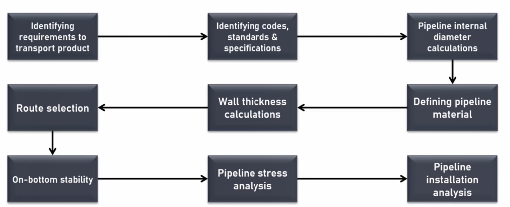
Identifying Requirements to Transport Product
This is the first step in sub-sea pipeline design. All the process requirements (like flow rate, temperature, pressure, etc) are identified in this stage. All the field surveys (such as bathymetric surveys, geotechnical surveys, tidal wave measurements, etc) must be carried out during this stage. These surveys are required to understand the nature of the sea bed and sea conditions that will be used during the detailed design process.
Identification of Codes and Standards for Sub-sea Pipeline Systems
There are various codes and standards that can be applicable to each subsea pipeline system design. So, in this stage, all such codes and standards are finalized. Some of the most common codes and standards for subsea pipeline systems are:
- DNV-OS-F101: Submarine pipeline systems
- DNV-ST-F101: Code compliance stresses
- DNV-RP-F109: On-bottom stability of submarine pipelines
- API-RP-1111: Design, Construction, and Operation of Offshore Pipelines.
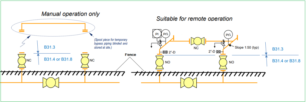
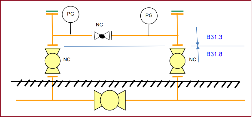
- ASME B31.3: Process Piping
Pipeline Internal Diameter Calculation
Hydraulic analysis is performed to find out the required pipeline internal diameters satisfying the governing code and standard requirements. The selected pipeline diameter should be adequate to deliver the required flow rate and pressure.
Deciding Pipeline Material
In this stage, a techno-commercial study is performed to find out the optimum material from the proposed materials. The selected material must be suitable for the given design pressure and economics.
Pipeline Wall Thickness Calculation
The minimum required pipeline wall thickness is calculated considering various parameters such as:
- External and internal design pressure
- Pipeline material
- Pipeline Diameters
- Buckling Consideration
Pipeline Route Selection
Before laying the pipeline, engineers conduct extensive surveys of the seabed to determine the most suitable route, taking into account factors such as water depth, seabed topography, and environmental concerns. Based on the bathymetric survey and other site investigation work, the pipeline route is selected to minimize unsupported pipeline length. The seabed in most cases will not be smooth. So, the route must be selected in such a way as to avoid long unsupported pipeline lengths.
On-Bottom Stability
In this stage, all the vertical and horizontal forces that act on a pipeline are calculated. It is ensured that the pipeline will be stable under the combined effect of all loads. All forces including sea waves, uplift buoyancy force, loads due to weight, etc are considered and checked. In situations when the pipeline is found to be unstable, additional stabilizing systems such as concrete ballast, rock dumping, concrete mattress, etc are introduced to make the subsea pipeline stable.
Pipeline Stress Analysis
In this stage, the complete pipeline configuration is modeled in available pipeline stress analysis software such as Caesar II or AutoPipe to find if the system is safe from all stress considerations. The results generated by these software programs are sufficient to judge the system and decide whether any modification is required or whether the system can be accepted as it is.
Pipeline Installation Analysis
This is the last stage of subsea pipeline design. In this stage, the stresses generated on the pipeline system during installation are investigated considering the installation methodology to be employed. Specialist professionals are contacted for this analysis purpose.
Construction and Installation of Subsea Pipelines
Subsea pipelines are engineering marvels, meticulously designed and constructed to withstand the extreme conditions of the marine environment. The construction process typically involves several key steps:
Pipeline Fabrication:
The pipeline segments are manufactured onshore using high-strength steel, with coatings applied to protect against corrosion and abrasion. These segments are then transported to the offshore installation site.
Installation:
Installation methods vary depending on factors such as water depth and seabed conditions. Common techniques include S-lay, J-lay, and reel-lay methods, each offering unique advantages depending on the project requirements.
Subsea Infrastructure:
In addition to the pipelines themselves, subsea infrastructure such as risers, manifolds, and subsea tie-backs are installed to facilitate the transportation and processing of hydrocarbons.
Subsea pipelines play a vital role in the global energy supply chain. It enables the development of offshore oil and gas fields that would otherwise be uneconomical to exploit, unlocking new sources of energy to meet growing global demand.