Compressors are intended to compress a substance in a gaseous state. Process compressors are used to compress a wide range of gases over a wide range of conditions. A Centrifugal compressor is a dynamic turbomachinery that increases the pressure of a gas by adding kinetic energy through an impeller. The famous French genius, Professor Auguste Rateau, invented the centrifugal compressor in the late 19th century. Smooth operation, large tolerance of process fluctuations, and higher reliability are the factors that Centrifugal compressors find extensive use in chemical and petrochemical industries. They are also used in small gas turbines.
Applications of Centrifugal Compressors
Centrifugal compressors are widely used in
- Refineries
- Gas field operations
- Natural Gas Compression & Transportation Services
- lifting
- reinjection
- gathering
- transmission
- storage
- Oil Exploration – Gas Reinjection, Gas lift, etc.
- Gas Liquefaction
- Air Compression service
- Refrigerant compression service
- Refueling applications
- Chemical Industries
- Fertilizers
- Pesticides
- Detergents
- Pharmaceuticals
- Paints
- Adhesives
- Organic and Inorganic chemicals
- Explosives
- Solvents
The following table provides some typical applications of centrifugal compressors
| Industry | Application | Service/Process | Typical Gas Handled |
| Gas Turbine | Power/Drive | Compression | Air |
| Iron and Steel | Blast Furnace | Combustion off gas | Air/Blast Furnace Gas |
| Iron and Steel | Bessemer Converter | Oxidation | Air |
| Iron and Steel | Cupola | Combustion | Air |
| Iron and Steel | Coke Oven | Compression | Coke Oven gas |
| Mining and Metallurgy | Power | For Tools and Machinery | Air |
| Mining and Metallurgy | Furnaces | Copper and Nickel Purification | Air |
| Natural Gas | Production | Re-pressuring oil wells | Natural Gas |
| Natural Gas | Distribution | Transmission | Natural Gas |
| Natural Gas | Processing | Natural Gasoline separation | Natural Gas |
| Natural Gas | Processing | Refrigeration | Propane and methane |
| Refrigeration | Chemical | Various Processes | Butane, Propane, Ethylene, Ammonia, Special Refrigerants |
| Refrigeration | Industrial and Commercial | Air Conditioning | Special refrigerants |
| Utilities | Steam Generators | Soot Blowing/Combustion/Cyclone Furnaces | Air |
| Utilities | City Gas | Manufacturing/Distribution | Fuel Gas |
| Miscellaneous | Sewage Treatment | Agitation | Air |
| Miscellaneous | Industrial Power | Power for tools and machines | Air |
| Miscellaneous | Paper Making | Fourdrinier vacuum | Air and water vapor |
| Miscellaneous | Gas Engines | Supercharging | Air |
The function of a Centrifugal Compressor
The centrifugal compressors within the above-mentioned industries serve the following purposes:
- Increasing (or reducing) gas flow pressure levels required for processing,
- Providing pressure differences to overcome system resistances, thus enabling gas flows through reactors, heat exchangers, and pipes, and
- Refrigerating gas flows for cooling and liquefaction.
Other functions of a compressor include
- Providing compressed gas or air for combustion.
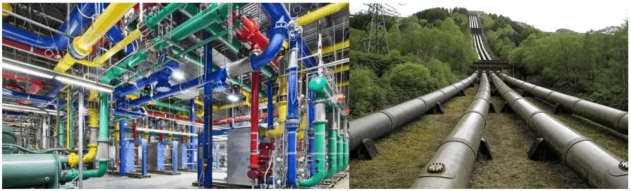
- Transporting process gases through pipelines.
- Provide compressed air for driving pneumatic tools.
- Circulating process fluid through a certain process.
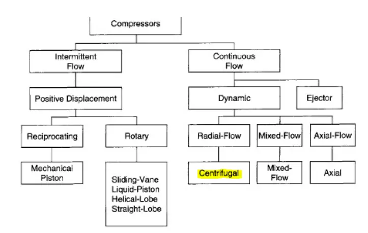
Basic types of compressors
Compressors are available in various types as listed below:
- Positive Displacement Compressors
- Reciprocating compressor
- Screw Compressors
- Centrifugal compressors
- Pipeline compressors
The following diagram shows a chart for basic compressor types.
Centrifugal Compressors
A Centrifugal compressor is a “dynamic” machine. It has a continuous flow of fluid that receives energy from an integral shaft impeller. The Energy transformed into pressure – partly across the impellers and partly in the stator section called diffusers. The main characteristics of a centrifugal compressor are
- Dynamic Compressor: Achieves a pressure rise by adding Kinetic Energy /Velocity to fluid
- Narrow operating range: Operates close to the design point due to its characteristics.
- Capacity control is simple using either a Suction Throttle or Speed Control.
- Can be used for pushing large volumes of gas (large volumetric capacity)
Why Centrifugal?
There are various benefits of being it centrifugal like
- It is a mature technology
- Suitable for large capacities
- Power Range from 0.4 to 40 MW
- Small footprint
- High Availability (99%)
- Less Maintenance
Parts of a centrifugal Compressor
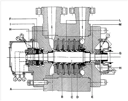
Refer to Fig. 2 below that shows the Cross section & parts of a typical centrifugal compressor:
- A. Outer casing
- B. Stator parts called ‘Diaphragm bundle’
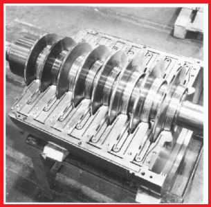
- C. Rotor
- D. Impellers
- E. Balance drum
- F. Thrust collar
- G. Hub
- H. Journal Bearing
- I. Thrust Bearing
- J. Labyrinth Seals
- K. Oil film end seals
How does a Centrifugal Compressor work?
Through the centrifugal compressor suction, the gas enters the rotating impeller. While passing through the blades, the gas is pushed by centrifugal force toward the impeller center. The impeller provides kinetic energy to the gas and the velocity increases. This kinetic energy is then converted into potential energy in the form of pressure increase. Again, while passing through a diffuser, the gas is compressed further. So, both the diffuser and impeller help in gas compression. On average, 65% of compression takes place in the rotor and 35% in the diffuser. For multistage centrifugal compressors, each stage increases the pressure which results in final higher pressure.
Types of Centrifugal Compressors
Depending on the number of impellers and casing design, centrifugal compressors are classified into three groups as follows:
- Integral Gear Type
- Single Stage
- Multistage
- Horizontal Split Casings
- Single Stage (Double Suction)
- Multistage
- Barrel Type Compressors
- Pipeline
- Multistage
Compressors with Horizontal Split casings (Fig. 3):-
Consists of half casings joined along the horizontal centerline, Employed for operating pressure below 60 bar.
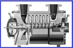
Compressors with Vertical Split casing/Barrel Type (Fig. 4):-
Vertical split casings are formed by cylinders closed by two end covers; hence ‘barrel type’ is used to refer to these compressors, Employed for high-pressure services up to 685 bar.
The Horizontal split casings & barrel compressors are further identified based on process stages, i.e.
- Multistage compressors with one compression stage
- Multistage compressors with two compression stages (Two compression stages set in the same machine/barrel casing. Between the two stages cooling of the fluid is performed in order to increase the efficiency of compression)
Basic Terminologies of Centrifugal Compressor
Surge: A phenomenon of instability that takes place at low flow which involves the entire system including not only the compressor but also the group of components traversed by the fluid upstream & downstream of it. Surge is characterized by intense and rapid flow and pressure fluctuation throughout the system and is generally associated with a stall involving one or more compressor stages. This phenomenon is generally accompanied by strong noise and violent vibrations which can severely damage the machine involved
Stall: Stall in turbomachinery describes as a situation in which due to low flow values, the stage pressure ratio or head does not vary in a stable manner with the flow rate.
Surge prevention: Surge prevention is effected through experimental tests in which pressure pulsation at a low flow rate is measured on individual stages. On this basis, it is possible to identify the flow values at which the stable operation of the stage is guaranteed.
Centrifugal Compressor Design Guidelines
1. Design Parameters: Centrifugal compressors in Process industries are designed following API 617. The following parameters are required to properly design a centrifugal compressor are:
- Type of gas
- Temperature, pressure, molecular weight, and corrosion properties of the gas.
- Possible gas fluctuations.
2. Flow Rates: A flow rate of approx. 180 m3/h is considered a minimum for any impeller. With a decrease in flow rate towards this limit, the efficiency of the centrifugal compressor falls.
3. Application Pressure Range: With proper seals, there is no limitation on lower pressures. However, the upper limit of operating pressure is limited by the use of thicker components and the number of stages in a single casing (generally limited to 8). For horizontally split designs, discharge pressures are generally up to 100 bar. For radially split (barrel) designs, discharge pressures can be up to 800 bar.
High suction pressures lead to difficulties in sealing and the majority of applications have suction pressures of less than 200 bar.
4. Application Temperature Range: The lower temperature can be as low as -75⁰C with due consideration of materials that provide ductility & sufficient brittle strength. Sealing materials should be compatible.
Commonly encountered higher temperature is 180-190⁰C. For higher temperatures up to 230⁰C cool buffer gas may be injected.
5. Number of Stages: The compression ratio or head defines the number of stages or impellers. A general rule is to have only nine impellers per casing in a single-section centrifugal & eight impellers per casing for a two-section centrifugal. In the special case of a compressor having a side stream entry, the maximum no of impellers should be seven per casing.
6. Rotating Speed: Higher rotative speeds give improved performance in terms of work per stage. A general rule of thumb is that impeller tip speed should normally range between 650 and 900 ft/sec (198 and 274 m/s) for fully enclosed impeller designs. For open impeller design, the maximum tip speed limit is higher due to the reduced centrifugal forces generated with the absence of the mass of the cover.
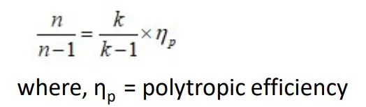
7. Compressor Efficiencies: In industrial applications of centrifugal compressors, two types of compressor efficiencies are used. They are Isentropic Efficiency and Polytropic Efficiency. Isentropic efficiency is given by isentropic compression work / actual compression work.
For centrifugal compressors, Polytropic efficiency is commonly used in work or power calculations. The polytropic process follows a path such that the polytropic exponent is constant during the process, PVn=constant; where: n= polytropic exponent. The polytropic exponent (n) and the isentropic exponent (k) (for an ideal frictionless adiabatic process) are related as follows:
The Polytropic efficiency can also be calculated based on the inlet volume flow since the polytropic efficiency is nearly proportional to the logarithm of the inlet gas volume flow rate.
Capacity Control
Capacity Control is used for the following:
- Process flow control
- To optimize fuel/power efficiency
- Pressure regulation
Capacity can be changed in several ways; below are some of them:
- Speed Regulation
- Control of Supply gas to the machine
- Bypassing the discharge flow back to the suction side of the machine
Type of Compressor Drives
Following are the various types of Compressor drives:
- Electric Motor Drives
- AC Squirrel cage Induction Motor
- Synchronous AC Motor
- Gas Turbines
- Steam turbines
- Variable Speed drives
- Variable Frequency Drive
- Variable speed (Hydraulic Coupling) drives
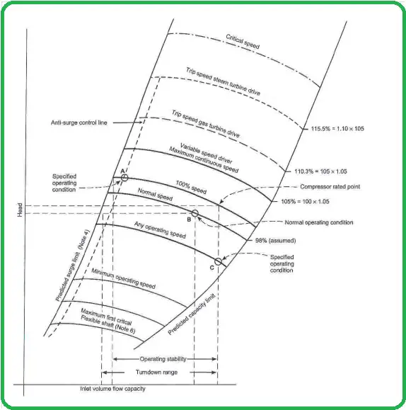
Typical Centrifugal Compressor Curve (Fig. 5)
Compressor Sealing System
The selection of a sealing system is critical for
- Satisfactory performance
- Reliability
The type of compressor & method of lubrication used will decide the type of sealing Technology. Sealing System can be divided into two classes based on the type of lubrication:
Contacting Sealing System
- Liquid Lubricated
- Gas Lubricated
Non – Contacting Sealing System
- Liquid Lubricated
- Gas Lubricated
The following are the utilities required for the Compressor:
- External Fuel gas for seal gas system
- Instrument Air for the Instruments/Control system/Seal gas system
Centrifugal Compressor vs Axial compressor
The main differences between a centrifugal compressor and an axial compressor are provided in the table below:
| Centrifugal Compressor | Axial compressor |
| In a centrifugal compressor, Gas enters the impeller axially and is discharged radially. | In an axial compressor, The gas enters and exits axially without directional change. |
| Easier to design and manufacture | Difficult to design and manufacture |
| The volume of gas flow is less | Can handle more gas flow. |
| Less efficient | More efficient |
| Can create more differential pressure in a single stage | Single-stage compression is not effective. |
Centrifugal Compressor vs Reciprocating Compressor
The main differences between a centrifugal compressor and a reciprocating compressor are listed in the following article: Difference between Centrifugal and Reciprocating Compressor. To understand the basic differences between a pump and a compressor click here.
Few more useful resources for you…
Articles related to Compressor
Articles Related to Pumps
Piping Design and Layout Basics
Piping Stress Analysis Basics
Piping Materials Basics
Articles Related to Mechanical Design
Articles Related to Process Design
Articles Related to Heat Exchanger