The word “Geography” though not used often by us in our daily life, but its presence, reference, and value have become an integral part of our activities in the way
- we do business,
- we communicate,
- we manage our resources
- the way we live.
We are in the age of Enterprise GIS which helps to solve
- Business problems
- Automate Business processes
- New ways to analyze business and spatial data by incorporating the knowledge of “Where” into the existing business models of “Why”, “What” and “When”.

What is Geographic Information System (GIS)?
A Geographic Information System (GIS) is a powerful tool used to capture, store, analyze, and present spatial or geographic data. It integrates hardware, software, and data to collect, manage, and display various types of information tied to specific geographic locations or spatial references.
GIS technology allows users to visualize, interpret, and understand patterns and trends in data that are associated with specific locations on Earth’s surface. This could include data such as land use, population demographics, environmental characteristics, transportation networks, and much more. By overlaying different layers of spatial data, GIS enables users to gain insights into relationships, make informed decisions, and solve complex problems related to geography and spatial analysis.
Applications of GIS are vast and diverse, ranging from urban planning, natural resource management, disaster response and mitigation, to business location analysis, epidemiology, and archaeology. It’s a fundamental tool in modern geography, environmental science, engineering, and many other fields where understanding spatial relationships is critical.
Components of GIS
A Geographic Information System (GIS) typically consists of several key components that work together to capture, store, manipulate, analyze, and present geographic data. These components include:
Hardware:
The hardware component of GIS includes computers, servers, storage devices, GPS receivers, scanners, and other devices used to collect, process, and store geographic data. The hardware infrastructure supports the execution of GIS software and the storage of large datasets.
Software:
GIS software provides the tools and functionality for performing various spatial data operations, including data input, manipulation, analysis, and visualization. Examples of GIS software include ArcGIS by Esri, QGIS, GRASS GIS, and Google Earth. These software packages often include modules for data management, spatial analysis, cartography, and remote sensing.
Data:
Data is a fundamental component of GIS and includes both spatial and attribute information. Spatial data represent the geographic features such as points, lines, polygons, and raster grids, while attribute data describe the characteristics or attributes of these features. GIS data can be collected from various sources, including satellite imagery, aerial photographs, GPS surveys, field measurements, and existing databases.
People:
GIS involves people who are responsible for designing, implementing, and using GIS systems. This includes GIS professionals such as GIS analysts, cartographers, and database administrators who manage GIS projects, create maps, and conduct spatial analysis. Additionally, stakeholders from various disciplines, such as urban planning, environmental science, and public health, may use GIS tools and outputs to support decision-making and problem-solving.
Methods/Procedures:
GIS methods and procedures encompass the workflows, techniques, and best practices used to collect, process, analyze, and present geographic data. This includes data acquisition methods, data processing algorithms, spatial analysis techniques, and cartographic principles. Standardized methods and procedures help ensure the accuracy, consistency, and reliability of GIS outputs.
Networks/Communication:
GIS often relies on network infrastructure and communication technologies to facilitate data sharing, collaboration, and remote access to GIS resources. This includes internet connectivity, intranet portals, web mapping services, and mobile applications that enable users to access GIS data and tools from different locations and devices.
GIS Mapping
The process of creating visual representations of geographic data using Geographic Information System (GIS) technology is known as GIS mapping. It involves the creation of maps that display various types of spatial information, such as geographical features, demographic data, infrastructure, and more, in a digital format.
GIS Survey
GIS Survey, also known as Geographic Information System Survey or GIS Mapping Survey, is a process of collecting, recording, and analyzing geographic data using GIS technology. This type of surveying involves gathering spatial information about specific features, locations, or attributes on the Earth’s surface and incorporating that data into a GIS database for further analysis and visualization.
GIS surveys can involve various methods and techniques for collecting geographic data, including:
- Field Surveys: These involve physically going to the location of interest and using GPS (Global Positioning System) devices or other surveying equipment to collect accurate coordinates and attribute data about features on the ground.
- Remote Sensing: Remote sensing techniques, such as satellite imagery, aerial photography, LiDAR (Light Detection and Ranging), or UAV (Unmanned Aerial Vehicle) drones, can be used to collect spatial data over large areas without the need for direct physical access.
- Data Compilation: GIS surveys also involve compiling existing geographic data from various sources, such as government agencies, organizations, or publicly available datasets, and integrating them into the GIS database.
- Attribute Collection: In addition to spatial coordinates, GIS surveys often involve collecting attribute data associated with geographic features, such as land use, population demographics, infrastructure details, environmental characteristics, and more.
Petroleum Industry – Need of Integrated Business-GIS:
The use of geography in analyzing and making decisions is not a new thing in the oil and natural gas industry. A good understanding of geography is required in every step of a petroleum industry starting
- from locating a place to drill a well,
- route a pipeline
- from the exploration site to the refinery plant,
- finding an ideal location for a refinery and a lot more
Scope of GIS Integration and Applications in Petroleum Industry
The petroleum Industry can be functionally divided into 2 categories.
- Production and Refining Sector.
- Retail Outlet Management and Distribution Network.
Productions and Refining Sector:
This involves the process of exploring new locations as petroleum reserves, managing the production of crude petroleum from earth strata, managing the pipeline network to transfer crude sources to refining plants, and facility management of various resources connected to such a huge industry.
1-Petroleum Exploration:
Exploration requires the analysis of a lot of different types of data such as satellite imagery, digital aerial photo mosaics, seismic surveys, surface geology studies, subsurface and cross-section interpretations and images, well locations, and existing infrastructure information.
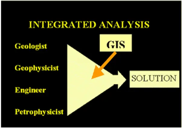
Analysis Process:
2-Production:
To produce found reserves, the company must first understand certain geographic, infrastructure, business conditions, and environmental factors about the area in question. GIS technology is ideally suited to this kind of overlay analysis.
3-Managing Facilities:
GIS can be used to map the gathering and transmission of products to a facility.
4-Pipeline Management:
Some of the variables include:
- Shortest distance from source to market
- Least grading (removal of trees, etc.)
- Costs association
- Number of stream, road, and railroad crossings
- Substrate (rock, soils, etc., associated with burial)
- Existing laws and regulations (wetlands, etc.)
- Utilization of existing utility corridors
Coverage analysis:
- Environmental damage
- Environmental response and investigation
- Criminal and civil penalties
- Environmental Remediation
- Damage to reputation and community relations
5-Retail Outlet Management and Distribution:
This is the area where a lot of GIS developmental activities can take place. Retail companies can use the power of GIS systems to optimize their business with intelligent analytical GIS tools and planning tools and provide better customer and outlet services.
Coverage Analysis:
- Fleet management –mapping of Petrol stations by brand, ownership, price, volume, shop size, or by any geography, such as country, postcode, catchments area
- Locating the Optimal position of a new outlet
- Optimal routing of Petroleum tankers across the country and across the city.
- Crisis management
- Volume distribution of petroleum products
- Geographic analysis of distribution pattern.
- Finding a specific outlet in a city and deriving a route to go there.
Importance of GIS in Pipeline Routing and Design
GIS (Geographic Information System) is of paramount importance in pipeline routing and design within the petroleum industry due to several reasons:
Spatial Analysis: GIS enables engineers to perform spatial analysis to identify the most optimal routes for pipelines. By integrating various spatial data layers such as terrain elevation, land cover, soil types, population density, and environmental sensitivity, GIS helps identify routes that minimize environmental impact, construction costs, and potential risks.
Data Integration: GIS allows for the integration of diverse datasets, including geological, environmental, regulatory, and socio-economic data, into a single platform. This integrated data facilitates comprehensive analysis and decision-making during pipeline routing and design processes.
Risk Assessment: GIS enables engineers to conduct risk assessments by identifying and analyzing potential hazards along proposed pipeline routes. Factors such as proximity to natural hazards (e.g., earthquakes, landslides), water bodies, population centers, and sensitive environmental areas can be evaluated to assess the likelihood and consequences of pipeline incidents.
Regulatory Compliance: GIS helps ensure regulatory compliance by incorporating legal and regulatory requirements into pipeline routing and design processes. By overlaying regulatory layers such as protected areas, land use zoning, and easement restrictions, GIS helps identify constraints and ensure that proposed pipeline routes comply with applicable laws and regulations.
Stakeholder Engagement: GIS facilitates stakeholder engagement by providing visualizations and interactive maps that allow stakeholders, including landowners, communities, and regulatory agencies, to understand and provide input on proposed pipeline routes. This transparency and communication help build consensus and address concerns early in the project lifecycle.
Emergency Response Planning: GIS supports emergency response planning by providing spatial data on critical infrastructure, emergency services, and evacuation routes. By integrating this information with pipeline routing data, GIS helps identify potential response challenges and develop effective emergency preparedness and response plans.
Construction Management: During the construction phase, GIS helps manage project logistics, track progress, and monitor environmental compliance. GIS-based tools enable real-time tracking of construction activities, materials inventory, and environmental monitoring, ensuring that construction activities adhere to project specifications and regulatory requirements.
Asset Management: Once pipelines are operational, GIS continues to play a vital role in asset management by providing spatial data for asset inventory, maintenance scheduling, and integrity management. GIS-based asset management systems help optimize maintenance activities, minimize downtime, and ensure the long-term reliability and safety of pipeline infrastructure.
GIS solutions:
- Corporate GIS data management
- Map production and presentation
- Digital Elevation Models and hydrology
- Environmental sensitivity analysis and modeling
- Pipeline route optimization and pipeline leakage risk
- Internet mapping and image web server solutions
- Workflow analysis
- Crisis Management on the Internet
- Conversion of current environmental data to GIS format
- Linkage of oil spill model to GIS.
- Retail market analysis.
- Distribution analysis.
- Market pattern analysis by demographics.
- 3-dimensional GIS
- Improved “Conflation” tools.
- Retail outlet supply routing and many more…
Future Expectations:
- Geologic Evaluation
- Reservoir Analysis (access to seismic data and well logs)
- Land / Lease Management
- Drilling Activity Analysis
- Competitor Analysis
- Gas Marketing
- Improved integration with our relational databases.
Video Tutorial on GIS
For further understanding of the subject of GIS, I suggest to go through the following video: