Welding is a fundamental process in many industries like oil and gas, construction, manufacturing, shipbuilding, automotive, and aerospace. It is used to join metals together by applying heat, pressure, or both to form a strong, permanent bond. While welding is a reliable and efficient method of joining materials, it must be done correctly to ensure the structural integrity of the welded joint and to avoid defects or failures. One critical aspect of the welding process is maintaining the proper minimum distance between two welding operations.
In this article, we will explore the minimum distance requirements between two welding operations, why they matter, and the factors that influence this distance.
What Is the Minimum Distance Requirement?
The minimum distance between two welding operations refers to the space that must be maintained between two adjacent welds. This is important for several reasons, such as avoiding heat-affected zone (HAZ) overlap, ensuring adequate access for welding tools, and promoting the overall quality and strength of the weld.
Welding operations are generally separated by a certain distance to:
Prevent Heat Interference: Overlapping heat-affected zones can weaken the material around the weld, compromising the joint strength.
Minimize Distortion: If two welds are too close together, the heat from one weld can affect the other, causing distortion in the welded materials.
Allow for Proper Cooling: Sufficient space allows the welded material to cool down between operations, reducing the risk of thermal stress and cracking.
Ensure Accessibility: Proper spacing ensures that the welder can work efficiently and safely, reducing the risk of weld defects due to inadequate access.
Compliance with Industry Standards: Certain industries or specific applications have strict welding standards that must be adhered to, including guidelines on the minimum distance between adjacent welds.
Why Is It Important to Maintain a Minimum Distance Between Two Welds?
Ensuring a proper distance between welds helps maintain the quality, strength, and safety of the structure being welded. Below are the key reasons why this distance is crucial:
Avoiding Overlapping Heat-Affected Zones (HAZ)
Welding creates a localized region of high heat, known as the heat-affected zone (HAZ), which can alter the microstructure and mechanical properties of the material. When two welds are made too close together, the HAZ of one weld can interfere with the HAZ of the adjacent weld. This can lead to reduced strength, increased brittleness, and a greater likelihood of cracking.
Prevention of Distortion and Warping
Welding generates significant heat, which causes the welded material to expand. As the weld cools, it contracts, leading to residual stresses. If two welds are too close, the thermal expansion and contraction of one weld can distort the adjacent weld, leading to warping or misalignment of the material.
Ensuring Proper Cooling
Cooling rates play a critical role in determining the final properties of a weld. The cooling process can be affected by the proximity of adjacent welds. When the cooling rate is not controlled or uniform, it can lead to issues such as weld cracking or inadequate solidification. Keeping an adequate distance between welds allows each weld to cool properly.
Providing Space for Inspection and Repair
Weld inspection is a critical part of the quality control process. A sufficient gap between two welding operations ensures that the inspector has the necessary space to assess each weld for defects such as porosity, undercuts, and cracks. Additionally, if a repair is needed, the welder will have enough space to carry out the repair work without damaging the surrounding area.
Reducing the Risk of Hydrogen-Induced Cracking
Hydrogen-induced cracking (HIC) is a common issue in welding, especially with high-strength steels. When the base metal is exposed to moisture or hydrogen during the welding process, it can lead to the formation of cracks. Maintaining a minimum distance between welds reduces the likelihood of hydrogen accumulating in one weld, which could then migrate to the other and cause cracking.
Factors Influencing Minimum Distance Requirements
Several factors influence the required distance between two welding operations. These include the material being welded, the welding process used, and the application’s requirements.
Material Type
The type of material being welded plays a significant role in determining the minimum distance between welds. For example:
Low-carbon steel: Low-carbon steels are more forgiving and may tolerate smaller gaps between welds.
High-strength steel: Higher-strength materials, such as high-carbon steels or alloys, are more sensitive to heat input and require more space between welds to prevent cracking or warping.
Non-ferrous metals: Materials like aluminum and titanium have different thermal properties and may require a different minimum distance compared to steel. For instance, aluminum requires a slower cooling rate to avoid brittleness, necessitating more space between welds.
Welding Process
The welding process used affects the heat input and cooling rate, which, in turn, influences the minimum distance between welds:
Arc Welding: Arc welding processes like Shielded Metal Arc Welding (SMAW) or Gas Tungsten Arc Welding (GTAW) tend to have higher heat input, requiring a larger minimum distance.
Laser Welding: Laser welding, which produces a concentrated heat source, may require smaller gaps due to the rapid cooling associated with the process.
TIG or MIG Welding: These processes offer more control over heat input and could potentially reduce the need for larger gaps between welds, depending on the material and application.
Weld Size
Larger welds produce more heat and can affect adjacent welds. As the size of the weld increases, the required minimum distance between welds also increases to prevent issues like distortion or overlapping HAZ.
Type of Joint
The configuration of the joint being welded can also influence the distance between adjacent welds. Butt joints, fillet welds, and lap joints each have different heat distribution characteristics, which will affect the recommended minimum distance.
Service Conditions
The intended service conditions of the welded structure can impact the minimum distance requirement. For example, structures subjected to high stress, pressure, or extreme temperatures may require more stringent requirements to maintain joint integrity.
Industry Standards and Codes for Minimum Distance Between Welds
Various organizations and standards bodies have developed guidelines for welding practices, including the minimum distance between welds. The minimum distance between welds is determined by the relevant codes and standards being followed. Below are some guidelines from commonly referenced codes and standards:
American Welding Society (AWS) D1.1: The minimum spacing between welds should be at least four times the thickness of the thinner part being joined, with a minimum of 1 inch (25 mm).
American Society of Mechanical Engineers (ASME) Boiler and Pressure Vessel Code (BPVC) Section VIII, Division 1: The minimum distance between welds should be at least three times the thickness of the thinner part being joined, with a minimum of 1 inch (25 mm).
European Welding Federation (EWF) and International Institute of Welding (IIW): The minimum distance between welds should be at least three times the thickness of the thinner part joined, but no less than 2 mm.
It is important to recognize that these guidelines are not comprehensive, and other codes and standards may have varying requirements. The actual minimum distance between welds can also depend on factors such as the materials used, the intended application, and the welding method employed. For precise guidance on the minimum distance between welds for a particular application, it is essential to refer to the relevant code or standard and/or consult a qualified welding engineer.
Minimum Distance Between Welds as per International Codes and Standards
The required minimum distance between welds is influenced by the welding process being employed. In most cases, this distance is determined by factors such as the material being welded, the joint design, and the parameters of the welding process. For instance, the typical minimum gap between fillet welds is around 1/16 inch (1.6 mm), though this value may change based on the material, joint configuration, and welding technique used.
Here is a table listing the minimum weld distance requirements by some of the widely used codes and standards:
Table 1: Minimum Weld Distances as per International Codes
AWS vs CWB
The American Welding Society (AWS) and the Canadian Welding Bureau (CWB) are two important organizations in the welding industry, each serving their respective countries. Although they share a similar focus on promoting welding safety, education, and certification, they differ in several key areas.
Founded in 1919, the American Welding Society (AWS) is a non-profit organization based in Miami, Florida, with over 70,000 members globally. The AWS is dedicated to advancing welding science, technology, and applications, which include processes like brazing, soldering, and thermal spraying. To achieve this, the organization develops codes, standards, and educational initiatives while also certifying welding professionals and inspectors.
The AWS is responsible for more than 200 codes and standards related to welding and joining processes. One of the most well-known standards is the D1.1 Structural Welding Code for Steel. These documents provide essential guidelines for welding procedures, welder qualifications, and inspection protocols. In addition, the AWS offers various educational opportunities such as webinars, seminars, and online courses. It also provides certification programs for welders and welding inspectors to ensure competency in the field.
On the other hand, the Canadian Welding Bureau (CWB), a non-profit organization founded in 1947 and based in Milton, Ontario, focuses on welding safety, education, and certification within Canada. The CWB serves over 6,000 members worldwide and offers a range of certification services for welding personnel and welding inspectors.
Similar to the AWS, the CWB has its own set of codes and standards, including CSA W59 Welded Steel Construction, which is comparable to the AWS D1.1. The CWB also provides training and educational resources, such as seminars, courses, and online tools. Additionally, the CWB certifies welding professionals and inspection experts through its certification programs.
Despite many similarities between AWS and CWB, there are notable differences. The AWS has a broader international presence and its standards are used globally, while the CWB is primarily focused on the Canadian market. Moreover, while both organizations offer certification for welding personnel and inspectors, the criteria and requirements for certification may vary between them.
In summary, the AWS and the CWB are both key players in the welding industry within their respective countries. They emphasize welding safety, education, and certification, and each has a set of standards to guide welding practices. However, their global reach and certification procedures differ, reflecting their distinct roles in the industry.
In conclusion, the minimum distance between two welding operations is a critical factor in ensuring the quality, strength, and safety of the welded structure. By maintaining adequate spacing between welds, you can avoid overlapping heat-affected zones, minimize distortion, promote proper cooling, and facilitate effective inspection and repair.
To determine the specific minimum distance for a particular welding project, consider the material being welded, the welding process used, the joint type, and the service conditions. Adhering to industry standards and codes will help ensure that your welding operations meet the necessary requirements for safety and performance.
Ultimately, the right spacing between welds contributes to the long-term durability and reliability of the structure, ensuring that it can withstand the demands placed upon it.
Top Instrumentation Engineering Deliverables for the Oil and Gas Industry Projects
Instrumentation engineering plays a crucial role in the oil and gas industry, ensuring the safe, efficient, and reliable operation of facilities across exploration, production, refining, and distribution. Instrumentation engineers are responsible for the design, implementation, testing, and maintenance of various measurement, control, and automation systems that regulate operations. These engineers work on a broad range of projects, including offshore platforms, refineries, gas plants, and storage facilities, providing essential solutions for managing pressure, temperature, flow, and level controls, as well as gas detection and safety systems.
What are Instrumentation Engineering Deliverables?
The deliverables in instrumentation engineering for the oil and gas industry refer to the comprehensive technical documents, designs, and systems that outline the specifications, functionalities, and implementation procedures of the instrumentation systems. These deliverables are vital to ensuring that the facility meets safety standards, regulatory compliance, operational efficiency, and environmental protection. Let’s learn some of the key instrumentation engineering deliverables that are most frequently used in the oil and gas industry.
Piping and Instrumentation Diagram (P&ID)
Instrument Index
I/O List
Instrument Specification and Datasheet
Instrument Loop Diagrams
Instrument Hook-Up Diagrams
Instrument Cable Schedule
Instrument Logic Diagrams
Cause and Effect Diagrams
Field Instrument Layout
Control System Architecture Documentation
Hazardous Area Classification
Testing and Commissioning Plans
As-Built Drawings and Documentation
1. Piping and Instrumentation Diagram (P&ID)
A P&ID, or Piping & Instrumentation Diagram, is a schematic representation of the functional relationship of piping, instrumentation, and system equipment components. P&ID shows all piping, including the physical sequence of branches, reducers, valves, equipment, instrumentation & control interlocks. Even though it is prepared by process engineers, most of the instrument-related inputs are shared by instrumentation engineers. More details about P&ID are covered here: What is a P&ID Drawing | P&ID Symbols | How to Read P & ID Drawings
Fig. 1: A snap of a Typical P&ID
2. Instrument Index
The Instrument Index is made to list all the instruments loop-wise on the basis of P&ID. It covers all the necessary information of the instruments in the loop. The major data that must be included in an Instrument Index are
Tag Number
Description of the Instrument
Service
Type of Instrument
Location of Instrument
P&ID Number
Instrument Specification Number
Hook-up Diagram Number
Instrument Layout Number
Fig. 2: Instrument Index
3. I/O List (Input-Output List)
The I/O List is used for defining the type of signal inputs & outputs of the instruments used. The main function of I/O lists is to define the number & types of signals given to PLC / DCS. This is the basic document used to size PLC / DCS. The main data that must be included in an I/O List is as follows.
Instrument Tag Number
Service
Signal Type
Signal Level
Instrument Range
P&ID Number
Fig. 3: Typical I/O List
4. Instrument Specification and Datasheet
Instrument specifications are one of the foundational deliverables in the instrumentation engineering domain. These documents define the technical requirements of each instrument in the system. Instruments used in the oil and gas industry typically include flowmeters, pressure transmitters, temperature sensors, control valves, gas detectors, and control panels.
Both P&ID & Process Data are required to prepare Instrument specification documents. It helps in specifying the precise requirement of the process for which the instrument is to be used. Purchasing an instrument is mainly dependent on instrument specification. The major data that must be included in the Instrument Specification Sheet is as follows.
Tag Number
Service
Instrument Function
Performance Criteria
Environmental Conditions
Power Supply Requirements
Communication Protocols
Material Specifications
Type of Instrument
Range
Size
Location
Mounting
Protection
Fig. 4: A Typical Instrument Datasheet
Accurate and detailed specifications are necessary for selecting appropriate instruments and ensuring compliance with safety regulations, such as those set by the International Electrotechnical Commission (IEC), the American Petroleum Institute (API), or other international standards or specifications.
5. Instrument Loop Diagrams (ILD)
Instrument Loop Diagrams are the graphical representation of loops. ILDs are made using the help of P&ID, I/O List, & Cable Schedule. ILDs show the detailed flow of signal from the instrument to the control system cabinet. The major data that must be included in an ILD are:
Components used the loop
Location of the components
Termination details
Interlocks used
Alarms
Soft functions
Fig. 5: A Typical Instrument Logic Diagram
These loop diagrams show how individual instruments connect to control systems, including wiring, sensors, and controllers.
6. Instrument Hook-up Diagrams
Instrument Hook-up Diagrams are the graphical representation of the method of connecting instruments to the process lines, equipment, tanks, vessels, etc. The main data that must be included in a hook-up drawing are.
Physical mounting of the instrument in the field
Various items used for mounting the instruments
Size & material of various items used
List of Tag Numbers for which the Hook-up is applicable
Fig. 6: A typical Instrument Hook-Up Diagram
7. Instrument Cable Schedule
A cable schedule is a document that contains the list of instrument cables. Each cable should have a precise number according to the numbering scheme. It is the most important document used for cable laying purposes in project engineering The main data included in the Cable Schedule is as follows.
Cable Number
Cable Connectivity
Type of Cable
Length of Cable
Size of Cable
Fig. 7: Typical Instrument Cable Schedule
8. Instrument Logic Diagrams
The major function of the Instrument Logic Diagram is to determine the operation of a given component or system as the various input signals change. The most common use of a Logic Diagram is to provide a simplified functional representation of an electrical circuit.
It is easier and faster to figure out how output functions and responds to various input signals by representing a circuit using logic symbols than using the electrical schematic with its complex relays and contacts.
Fig. 8: A Typical Instrument Logic Diagram
9. Cause & Effect Diagrams
The Instrument Cause & Effect Document is a tabular chart of the functions of various instruments. This document indicates the cause as an instrument signal in one condition and its effects on other instruments connected in the loop as per the logic.
Fig. 9: Cause and Effect Diagram
10. Field Instrument Layout
Instrumentation layout plans define where and how instruments will be physically positioned within the facility. These deliverables are critical for ensuring that instruments are accessible for maintenance, calibrated correctly, and located in safe zones. Layouts are especially significant in the oil and gas industry due to the high-risk environments involved.
Field instrument placement plans consider the following factors:
Accessibility: Instruments must be placed in locations that are easy to access for calibration, inspection, and repair.
Safety Zones: Placement in hazardous areas requires adherence to explosive-proof and weather-proof guidelines. Instrument placement must avoid areas that could lead to failure or danger in the event of fire or explosion.
Interference Avoidance: Instruments should be placed away from sources of vibration, excessive heat, or electromagnetic interference, which could affect measurement accuracy.
Environmental Considerations: Temperature, humidity, corrosion, and exposure to harsh chemicals must all be considered when positioning field instruments.
Proper instrument placement ensures ease of operation and minimizes downtime during maintenance or upgrades.
11. Control System Architecture Documentation
This deliverable provides an in-depth overview of the architecture of the control systems, which are the central nervous system of the entire oil and gas facility. The control system architecture typically includes:
Distributed Control System (DCS): A centralized control system that allows operators to monitor and control processes across various parts of the plant.
Programmable Logic Controllers (PLC): Used for local control of equipment, PLCs are often deployed in safety-critical applications where real-time decision-making is needed.
Human-Machine Interface (HMI): Provides operators with graphical interfaces to monitor system performance and intervene when necessary.
Redundancy Plans: These are critical for ensuring continuous operation, especially in oil and gas facilities where downtime can result in significant financial losses or safety hazards.
Communication Networks: Describes how devices will communicate with each other using protocols such as Ethernet, Modbus, or wireless technologies.
This documentation is vital for understanding how various systems will interact and ensuring the seamless operation of the entire plant.
12. Hazardous Area Classification and Equipment Certification
One of the critical deliverables in instrumentation engineering for the oil and gas industry is the classification of hazardous areas and the certification of equipment. The oil and gas industry often involves environments with explosive gases or vapors, particularly in offshore and underground drilling operations.
The deliverables in this category typically include:
Hazardous Area Classification: This process involves analyzing the facility to determine the likelihood of the presence of flammable gases or vapors. Areas are classified into zones (Zone 0, Zone 1, Zone 2) depending on the likelihood and frequency of a hazardous atmosphere.
Equipment Certification: Instruments and electrical equipment used in these zones must be certified to meet explosion-proof standards, such as IECEx or ATEX certifications, ensuring they are safe for use in hazardous conditions.
Explosion Protection Methods: The design and implementation of protection techniques like intrinsic safety (Ex i), flameproof (Ex d), and increased safety (Ex e).
Proper hazardous area classification and equipment certification ensure the safety of the facility, its workers, and the surrounding environment. More details about Hazardous Area Classification is covered here: What is Hazardous Area Classification? Steps and Guides
13. Testing and Commissioning Plans
Before the instrumentation systems are fully integrated and operational, testing and commissioning are necessary to ensure everything is working as expected. These deliverables consist of:
Factory Acceptance Test (FAT): This test is conducted at the manufacturer’s facility to ensure that the instruments meet the required specifications before shipping. Further details about FAT can be read from here: Factory Acceptance Test– What Is FAT, and How Does It Work?
Site Acceptance Test (SAT): Once the equipment is installed on-site, it undergoes testing to verify that it operates correctly in the actual environment.
Calibration Reports: Detailed reports on the calibration of each instrument, ensuring they meet accuracy and precision standards.
Performance Testing: Testing under operating conditions to confirm the entire system’s functionality, including communication protocols, control logic, and emergency shutdown systems.
A comprehensive testing and commissioning plan is essential for identifying potential issues early, minimizing risks, and ensuring the system is safe, efficient, and compliant with regulatory standards.
14. As-Built Drawings and Documentation
As-built drawings are one of the final deliverables in the instrumentation engineering phase. These documents provide a detailed, up-to-date representation of the system as it has been installed, including any changes or deviations from the original design. They include:
Revised P&IDs: Updated diagrams reflecting any changes during construction or installation.
Instrument Datasheets: Finalized datasheets with actual specifications of the installed instruments.
Loop Diagrams: Updated to reflect the actual wiring and instrument configurations used during installation.
As-built drawings are essential for future maintenance, troubleshooting, and potential upgrades, serving as a historical record of the project.
Some other deliverables generated by Instrumentation Engineers are:
Safety Instrumented System (SIS) Design: Includes the design of fail-safe systems, emergency shutdown (ESD) systems, and safety integrity levels (SIL) to protect against hazards and ensure personnel and equipment safety.
PSV Sizing Calculation
Control Valve Sizing Calculation
Instrument Location Plan
Junction Box grouping and Location Plan
Cable Tray Layout
Preparation of Material Requisition for Instrument Items
Technical Bid Evaluation or Technical Bid Analysis
Fire Alarm & CCTV Layout
Fire Alarm Block Diagram
CCTV Block Diagram
Instrument – Electrical Interface Drawing
Instrument – Piping Interface Drawing
Instrument Earthing Philosophy Drawing
Instrument Design Basis/Philosophy
Pipeline Leak Detection Philosophy
Metering Philosophy and Specification
Telecomms Philosophy
Control and Safety System Topology Diagram
Telecoms Block Diagram
EDS Philosophy
Telecommunication System Functional Specifications
Integrated Control & Safety System (ICSS) Specification
ASME B31.3, the “process piping” code, provides guidelines for the pressure leak testing of piping systems. The primary goal of these tests is to ensure the integrity and safety of the piping system before it is put into service. As the name suggests, we just want to see if the piping we have designed and fabricated is not going to leak when put into operation. They basically serve two main purposes, as mentioned below:
Determine the leak tightness of the welded and flanged joints of the piping system and
“Pressure Leak Test” is a general name. The more specific name depends on how you are going to execute the test. There are 6 types of methods stated in the code as below:
1. Hydrostatic Leak Test
Hydrostatic leak test, or simply Hydrotest, is the most common type of test that uses water as the test fluid. Tested at 1.5×Design Pressure×Ratio of Stress (that normally ends up as 1, unless operating at very high temperature). Only if a hydrostatic test could cause damage to the piping or is impractical, a pneumatic leak test be proposed as an alternative type of pressure leak test.
2. Pneumatic Leak Test
Using inert gas or air as the test fluid with 1.1×Design Pressure. This test must be carefully assessed as it presents hazards from the stored energy of compressed fluid during the test that could burst if a failure occurs.
3. Hydrostatic-Pneumatic Leak Test
Same as method 2, where a hydrostatic test may not be suitable; a combination of both hydrostatic & pneumatic tests could be proposed. However, I have never experienced such tests being conducted. If you have any insights about how it is done, please share them in the comment section.
4. Initial Service Leak Test
With the owner’s approval, this test is only applicable to Category D fluid service. It is tested during the initial operation of the system with the service fluid itself. Pressure testing is the same as operating pressure.
5. Sensitive Leak Test
Sometimes, it is also known as a bubble test. The test pressure is only 105 kPa, or 25%×Design Pressure. This test is required for Category M fluid service as an additional pressure leak test on top of the hydrostatic or pneumatic test.
6. Alternative Leak Test
Where both hydrostatic and pneumatic tests are not feasible, an alternative leak test can be proposed. It consists of 3 procedures:
Examination of all welds
Flexibility analysis to be passed
Performing a Sensitive Leak Test
Requirements for Leak Pressure Tests
Piping that is open to the atmosphere does not need to be leak tested, UNLESS, of course, specified by the owner or engineering design. The reason is that it is not an enclosed pressurized piping; the system has no pressure to retain.
Category D piping systems can be tested using only the Initial Service Leak Test, PROVIDED; of course, it is approved by the Owner. So, if your projects face a setback schedule during testing, getting approval on this might make a difference in the overall progress.
The pressure during the leak test only needs to be maintained for AT LEAST 10 minutes! The setup, fluid filling, and staggered pressurization are what take the most time. That is why if you could get Category D tested with only the Initial Service Leak Test, it would save lots of time!
The pressure leak test shall be conducted after all required heat treatments have been completed. Yup, it’s kind of logic, isn’t it?
Once a pressure leak test has been completed, if any repairs or modifications are made, the piping system shall be retested. Can this be waived if the changes are minor? Of course, with the Owner’s approval. The trick is, how minor is considered minor? You will need to justify that.
All joints shall be exposed during the pressure leak test. Therefore, it is preferable that they are not painted beforehand. Paint may hinder any small leak point from being visible.
If a pneumatic pressure test is specified, the hazard from stored energy shall be assessed. One way to do this is by using calculations in ASME PCC-2. The code provides guidelines for safe distance from the piping that is being pneumatically tested. Did you know the lowest distance is 50 m?
What is a Weep Hole in Piping and Pressure Vessels?
In the world of piping and pressure vessel engineering, small details can have a significant impact on the integrity and safety of a system. One such detail is the weep hole—a small but essential feature that plays a key role in ensuring proper functionality and preventing leaks in critical systems. In this article, we’ll explore what a weep hole is, its functions, and why it is an indispensable part of pressure vessel and piping design.
What is a Weep Hole?
A weep hole is a small opening that is strategically placed in pressure vessels, piping systems, or reinforcement pads. In pressure vessel and piping engineering, the weep hole’s primary function is to allow gas or fluid to escape, preventing dangerous pressure build-up and ensuring the structural integrity of the system. Though it’s a simple feature, it serves several crucial purposes during both construction and operation. Weep holes in piping are also known as a tell-tale holes or vent holes. Fig. 1 below shows an example of week-hole for better explaining it
The Role of Weep Holes in Pressure Vessel and Piping Systems
Weep holes are typically integrated into reinforcement pads or welded connections on pressure vessels and piping systems. These pads are added to strengthen areas where nozzles or branches are welded onto the main vessel. However, cutting holes in a pressure vessel to install nozzles can weaken the structure. To compensate for this weakness, reinforcement pads are added, but without a proper means of venting trapped gases during welding, pressure can build up and cause issues. That’s where the weep hole comes in.
Here’s how weepholes function in pressure vessel and piping systems:
1. Venting Gases During the Welding Process
One of the main functions of a weep hole is to act as a vent during the welding of a reinforcement pad. When welding a pad to a nozzle or branch, gases and smoke can become trapped in the space between the pad and the vessel. If these gases are not allowed to escape, pressure can accumulate and cause safety hazards or welding defects. The weep hole provides an outlet for these gases, allowing them to escape during the welding process and preventing the reinforcement pad from becoming a “jacketed” vessel. This venting ensures that the welding process is completed safely, with no risk of pressure-related complications.
Once the welding and pressure testing are complete, the weep hole is sealed to ensure that no further gas or fluid can escape during operation.
2. Enabling Pressure Testing
After installation, weep holes also serve a critical role in pressure testing. The weep hole is typically threaded to accommodate a test gauge, such as a 1/4″ NPT thread. This allows engineers to perform an air or soap test to check for leaks in the system. By applying pressure through the test gauge, it’s possible to detect any leaks around the nozzle and reinforcement pad connection.
If a leak is detected, corrective measures can be taken before the system is put into service. The weep hole thus provides an effective means of testing the integrity of the welds and ensuring that the pressure vessel or piping system is leak-free and safe to operate.
3. Acting as a Telltale for Future Leaks
In the event that a leak occurs in the future, the weep hole acts as a tell-tale, providing early detection of potential issues. If a leak develops beneath the reinforcement pad—due to a crack, corrosion, or other failure—the weep hole allows any gas or liquid to escape, signaling that there may be a problem.
This early detection is vital, as it allows maintenance teams to address issues before they escalate into more severe problems that could compromise the safety or functionality of the system. The weep hole, in essence, serves as a built-in monitoring tool, offering a simple but effective way to spot leaks early.
4. Preventing Dangerous Pressure Build-Up
Another essential function of the weep hole is to prevent the dangerous buildup of pressure within the system. If a leak occurs but goes unnoticed for a period, pressure may begin to accumulate inside the vessel or pipe. Left unchecked, this pressure could lead to further damage or even catastrophic failure. The weep hole ensures that any pressure buildup is relieved gradually, reducing the risk of such failures. By allowing gas or liquid to escape through the hole, the system remains under control even when minor leaks develop.
Sealing the Weep Hole After Testing
Once the pressure test is completed and no leaks are detected, the weep hole is sealed. Typically, this is done by welding the hole shut to prevent any future leakage. Sealing the weep hole ensures that the system remains airtight and safe under operational pressures.
Weep holes are a small yet crucial parts in piping and pressure vessel engineering. Their primary functions—venting gases during welding, enabling pressure testing, providing early leak detection, and preventing pressure build-up—contribute to the safety, durability, and functionality of critical systems. Whether used in the construction phase or as part of ongoing system monitoring, weep holes ensure that pressure vessels and piping systems remain secure and efficient throughout their service lives.
Incorporating weep holes into design and construction is an effective strategy for maintaining structural integrity and reducing the risk of system failures, making them an indispensable feature in the engineering of pressure vessels and piping systems.
Creep Fundamentals and How ASME BPVC Address This Phenomenon
This not-so-brief write-up is basically a summary of my notes on this subject when several years back I decided to study this interesting subject in somewhat detail. For interested readers, this is only a microcosm and references cited in this write-up should be referred to for details. The references cited forms the basis of this write-up, including the figures used. The issue of compressive stress has not been discussed in this write-up. I am hopeful that this write-up will give useful pointers to a reader interested in delving into this subject in greater detail.
1.0 Basics of Creep
Creep is time dependent deformation at constant stress. A schematic arrangement for creep testing is shown in Figure 1.
Figure 1-Conceptual example of creep test [1]
Usually, three stages are observed in creep tests; the primary stage where the strain rate increases initially before it reduces and takes a steady value (secondary creep), and towards the end of secondary creep there is an unstable increase in strain rate leading to rupture.
The curve shown in Figure is an idealized curve, and for some materials, secondary creep may not occur. Steady-state creep rate is one of the important outputs of a creep test result. Stress-strain curves for various constant values of time called isochronous curves are often needed in design. They are constructed from strain versus time data for various stress levels. Figure 3 and Figure 4 show the construction of an isochronous curve. Strains corresponding to a time say 𝑡1 is obtained as in Figure 3, and they are then plotted against various stress values as in Figure 4, forming the isochronous stress-strain curve for time t1. Similar curves can be constructed for other values of times 𝑡2 and 𝑡3 so that a family of stress-strain curves is formed.
Figure 2- Three stages of Creep [1]
Figure 3- Strain at different times for various constant stress levels [1]
Figure 4- Development of Isochronous curve [1]
2.0 Time-temperature parameters in Creep analysis
Development of cracks, crazing (network of fine cracks) as well as other mechanisms contribute to leading creep deformation to the point of rupture. A big challenge lies in extrapolation of test data. A piping or pressure vessel component may have a design life of 20 years or ore but the test data is usually available for 10,000 hours. If extrapolation is done, abrupt changes in slope may occur due to shift in the creep mechanisms. A more successful approach is to use data from relatively short time tests, but at temperatures above the service temperature of interest, to estimate the 3behavior for the longer time at the service temperature. Under these circumstances, a common physical mechanism for tests and service is more likely than for extrapolation at constant temperature. Such approaches involve use of time-temperature parameters. I will briefly discuss two approaches, the Sherby-Dorn Parameter and Larson-Miller parameter.
2.1 Sherby-Dorn parameter
Arrhenius rate equation is the basis of the Sherby-Dorn parameter. A key assumption is that the activation energy for creep is constant.
Arrhenius equation is
If we integrate the equation and discard the constant of integration so that only the steady state creep strain occurs, we get
Where 𝜃=temperature-compensated time.
In Ref [1] it has been shown that the Creep strain at rupture is fairly constant for a given value of temperature-compensated time 𝜃𝑟 to rupture for various Aluminium alloys. Hence 𝜃𝑟 depends only on stress, so for a material there should be a single curve relating 𝜃𝑟 and stress for various combinations of temperature 𝑇 and rupture time 𝑡𝑟. Sheldon-Derby parameter is defined as 𝑃𝑆𝐷=log 𝜃𝑟.
Taking logarithm to base 10 on both sides of Equation 4, we get
Figure 5-Sherby-Dorn parameter [1]
A family of parallel straight lines is expected, one for each value of stress. These lines have slopes given by 0.217𝑄 and each intercept at 1/𝑇=0 can be interpreted as the 𝑃𝑆𝐷 value for that stress. Once 𝑄 is known, stress-life data can be employed to make a plot of 𝑃𝑆𝐷 versus stress.The data for all stresses and temperatures should fall together along a single curve, with the correlation of the data being a measure the success of the parameter for any particular set of data. Using such a plot and equation [5], we can determine rupture times 𝑡𝑟 for particular values of stress and temperature. The test data used to obtain 𝑃𝑆𝐷 versus 𝜎 plot generally involve shorter rupture times than the service lives of interest. Hence, the test data at relatively short 𝑡𝑟 and high temperature can be used to predict the behavior at longer 𝑡𝑟 and lower temperature.
Figure 6-Sherby-Dorn parameter vs. Hours [1]
2.2 Larson-Miller parameter
Larson-Miller parameter is an analogous approach to Sherby-Dorn but uses different assumptions. The Larson-Miller parameter can also be derived from Equation [4] substituting θ=𝜃𝑟 and t=𝑡𝑟 and taking logarithm to base 10 of of sides. However, Q is assumed to vary and 𝜃𝑟 to be constant. The Larson Miller parameter is defined as 𝑃𝐿𝑀=0.217𝑄 and a constant 𝐶=−log 𝜃𝑟 is used. On this basis we get
Figure 7-Larson-Miller parameter [1]
The value of 𝐶 can be interpreted as an extrapolated intercept on the plot of log 𝑡𝑟 versus 1/𝑇 as shown in Figure 1
Figure 8-Correlation between LM parameter and Creep rupture data for S-590 [1]
3.0 ASME codes and Creep
3.1 Allowable stress
For Section 1 and Section VIII -1 applications, allowable stress criteria are given in Appendix 1 of Part D. The allowable stress at elevated temperature is the lesser of:
a) the allowable stress given by the criteria based on yield and ultimate strength
b) 67% of average stress to cause rupture at 100,000 hours
c) 80% of the minimum stress to cause rupture in 100,000 hours and
d) 100% of the stress to cause a minimum creep rate if 0.01%/1000 hrs.
About 1500F, however, the factor on average stress to rupture is adjusted to provide the same time margin on stress to rupture as existed at 1500F. Although the allowable stress is a function of the creep rupture strength at 100,000 hours, this is not intended to imply that there is a specified design life for these applications. There are additional criteria for welded pipe and tube that are 85% of the above values.
Unlike previous editions, the 2007 edition of Section VIII D2 covers temperatures in the creep regime. The time-dependent allowable stress criteria for VIII-2 are the same for VIII-1. However, because the time independent criteria are less conservative, tensile strength divided by a factor of 2.4 or 3.5 , the temperature at which the allowable stress is governed by time-dependent properties is lower in VIII-2 than VIII-1.
The allowable stress criteria for components of Class 1 nuclear systems covered by Subsection NH of Section III, of the ASME B&PV code are different than for non-nuclear components. For these nuclear components, the allowable stress at operating conditions for a particular material is a function of the load duration and is the lesser of :
a) the allowable stress for Class 1 nuclear systems based on yield and ultimate strength
b) 67% of the minimum stress to rupture in time, T
c) 80% of the minimum stress to cause initiation of third stage creep in time, T and
d) 100% of the average stress to cause a total ( elastic-plastic and creep) strain of 1% in time, T.
These allowable stress criteria are more conservative than for non-nuclear systems for the same 100,000-hour reference time.
However, these allowable stresses apply to operating loads and temperatures, generally not defined as conservatively as the design conditions to which the allowable stresses apply for non-nuclear applications. There are also additional criteria for allowable stresses at welds and their heat-affected zone [2].
The allowable stresses for class 2 and 3 elevated temperature nuclear systems are in general similar to those for non-nuclear systems. Subsection NB covers class 1 nuclear components in the temperature range where creep effects do not need to be considered.
3.2 Members in bending
Generally, two equations are used for stress and strain in the creep regime: Norton’s equation and the elastic analog method [2].
Norton’s equation relates strain rate to stress [2]
Norton’s equation is difficult to implement for most real-life problems. The complexity arises from the non-linear relationship between stress and strain rate. In addition, the equation has to be integrated to obtain stress and deflections.
The elastic analog method is [2]
The assumptions for bending of beams in the creep regime are based on assumptions that are similar to those for beams in elastic analysis, as:
a. The length of the beam is much larger than the cross-section.
b. Plane cross sections remain plane after bending.
c. Bending deflections are small in comparison to the length of the beam.
d. Stress-strain diagrams are the same for both the tensile and well as compressive sides of the beam.
e. The plane of bending is the plane of symmetry.
Strain at a given point in a beam due to bending is
Where 𝑧=location of a point measured from the neutral axis 𝜌= radius of curvature
The beam is assumed to have achieved a stationary stress condition. Then, using equations 8 and 9, we get [2]
3.3 Load and displacement controlled limits for components operating in the Creep regime
The below diagram [2] shows the limits set out in ASME SEC III NH for Creep range for Load and displacement-controlled limits
Figure 9- Flow Diagram for Elevated temperature analysis NH-3221-1[2] [3]
A noticeable change in Subsection NH with respect to ASME SEC VIII D2 Part 5 is in the second row of Figure 9. The 1.5𝑆 limit does not apply when loading conditions are of sufficient durations in the creep regime for creep effects to redistribute elastically calculated stress and strain. This is reflected by the 𝐾𝑡 factor in the stress evaluation in ASME SEC III-NH.
The procedure for strain and deformation limits is intended to prevent ratcheting. Section III-NH gives the designer the option to using three methods for analysis they are elastic, simplified-inelastic and inelastic analysis. The object of all these methods is to limit the strains in the operating condition to 1% for membrane, 2% for bending and 5% for local stress. At welds, the allowable strain is one half those values. A point to note: a 1% strain in a flange may result in an unwanted leakage, whereas the same strain at the junction of a flat head to shell junction may be acceptable.
The elastic method, which is very conservative, is generally applicable when the primary plus secondary stresses are below the yield strength. The simplified inelastic analysis, which has less conservative built into it compared to the elastic analysis, is based on rounding the accumulated membrane strain. The last option is to perform an inelastic analysis. The inelastic analysis yields accurate results but has the drawback of being expensive and time consuming to perform. It requires a large amount of material property data that may not be available for material under consideration.
One potential disadvantage of using the strain and deformation controlled limits of III-NH is that it requires separate treatment of primary and secondary stress categories. This condition is validated in Sec VIII D2 by combining the primary and secondary stress categories into one quantity. For simple structures, the separation of primary and secondary stresses in III-NH may not be a big problem. But for most complex structures with asymmetrical geometry and loading, it can be difficult, if not impossible, to sort out primary and secondary stress categories from a detailed finite element analysis. Section III-NH however does give the designer the option, called test A-3, to use the combination of primary plus secondary stress limits similar to VIII-D2, when the effects of creep are negligible. This creep modified shakedown limit avoids the potential problem of separating primary and secondary stresses [2].
3.3.1 Elastic analysis
The strain and deformation limits in the elastic stress analysis are considered to be satisfied if they meet the requirements of A-1, A-2 or A-3. The membrane and bending stresses used in these tests are defined as [2]
Test A-1
This test applies for cycles where both extremes of the cycle are within the creep range of the material. The governing equation is
Where 𝑆𝑎 is the lesser of
a. 1.25𝑆𝑡 using the highest wall averaged temperature during the cycle and time value of 104 hours.
b. The average of the two 𝑆𝑦 values associated with the maximum and minimum wall averaged temperature during the cycle.
The requirement of item (a) is based in the concern that creep relaxation at both ends of the temperature cycle will increase the potential for ratcheting. Experience [2] has shown that using a value of 𝑆𝑡 at 104 hours as a stress criterion us a realtistic assumption. The requirement of (b) is based in on averaging the yield stress associated with the maximum and minimum temperatures as a good approximation.
Test A-2
This test is applicable for those cycles in which the average wall temperature at one of the stress extremes defining the secondary stress range, 𝑄, ks below the temperature shown in Figure 10
The values shown in Figure 10 are the approximate temperatures above which the material allowable stress values at 100,000 hours are controlled by creep and rupture.
Figure 10- Temperature limits [2]
Test A-3
This test, although applicable to all conditions, was originally intended for components that are in the creep range for only a portion of their expected design life. Compliance with this test indicate that creep is an issue is not an issue and the rules of VIII-D2 be used directly. The calculated stresses are satisfied when all of the following criteria are met:
The simplified inelastic analysis is based on the concept of requiring membrane stress in the core of a cross-section to remain elastic, whereas bending is allowed to extend in the plastic region. This concept is based on the Bree diagram. The Bree diagram assumes secondary stress to be mainly generated by thermal gradients. Figure [12] from Reference [2] is plotted with primary stress as the abscissa and the secondary stress as the ordinate. The diagram is divided into various zones that define specific stress behavior of the shell. It assumes an axisymmetric thin shell with an axisymmetrc loading. It also assumes the thermal stress to be linear across the thickness. For a detailed derivation and assumptions relating to Bree diagram Appendix A of Reference [2] can be referred to.
The various limitations and zones of the diagram are as follows
Figure 12-Bree Diagram [2]
Limitations [2]
It is assumed that the material has an elastic perfectly-plastic stress-strain diagram.
Because mechanical stress is considered primary stress, it cannot exceed the yield stress value of the material. Thermal stress, on the other hand is considered secondary and this exceed the yield stress of the material.
Initial evaluation of the mechanical and thermal stresses in the elastic and plastic regions was made without any consideration to relaxation or creep.
Final results were subsequently evaluated for relaxation and creep effect.
It is assumed that stress due to pressure is held constant, while the thermal stress is cycled. Hence, pressure and temperature stress exist at the beginning of the first half of the cycle and only pressure exists at the end of the second half of the cycle.
Zone E
Stress is elastic below the creep range
Ratcheting does not occur below the creep range.
Stress redistributes to elastic values above the creep range.
Zone S1
Below the creep range, the stress is plastic on the outside surface of the shell during the first half cycle. The stress shakes down to elastic in all subsequent cycles.
Ratcheting does not occur below the creep range.
Ratcheting occurs in the creep range.
Shakedown is not possible in the creep range.
Zone S2
This zone is a subset of zone S1.
Below the creep range, stress is plastic on both surfaces of the shell during the first half of first cycle. Stress shakes down to elastic in all subsequent cycles.
Ratcheting does not occur below the creep range.
Ratcheting occurs in the creep range.
Shakedown is not possible at the creep range.
Zone P
In this zone, alternate plasticity occurs in each cycle below the creep range.
Shakedown is not possible below as well as in the creep range.
Failure occurs due to low cycle fatigue below the creep range.
Shakedown is not possible at the creep range.
Zone R1 and Zone R2
Ratcheting occurs below and in the creep range.
Shakedown is not possible below as well as in the creep range.
Actual diagram from ASME III-NH is shown in Figure 13 . Z lines of constant elastic core stress values. The key feature of the technique is identifying an elastic core in a component subject to primary loads and cyclic secondary loads. Once the magnitude of this elastic core has been established, the deformation of the component can be bounded by noting that the elastic core stress governs the net deformation of the section. Deformation in the ratcheting, R, regions of the Bree diagram can be estimated by considering individual cyclic deformation. The ASME simplified inelastic analysis procedure for strain limits consists of satisfying test B-1, test B-2 or test B-3.
Figure 13 Effective Creep stress parameter Z for simplified inelastic analysis using test numbers B-1 and B-3(ASME-III NH) [2]
For the tests B-1, B-2 and B-3,
X includes all membranes, primary bending and secondary bending stresses due to pressure induced as well as thermal induced membrane stresses.
Y includes all thermal secondary stresses
𝑆𝑦𝐿 Is the yield stress at the cold end of the cycle.
The following conditions must be met to satisfy B-1 and B-2 tests [2]
The average wall temperature at one of the stress extremes defining each secondary equivalent stress range 𝑄, is below the applicable temperatures in Figure 10.
The individual cycle cannot be split into sub-cycles.
Pressure –induced membrane and bending stresses and thermal induced membrane stresses are classified as primary stresses for purposes of this evaluation.
Definitions of X and Y in Equation 19 and 20 apply for these two tests except that the value of 𝑆𝑦 as defined in these two equations is replaced with 𝑆𝑦𝐿 the yield stress at the lower end of the cycle.
These tests are applicable only in regimes E, 𝑆1, 𝑆2 and P in Figure 13
The procedure for this test consists of calculating the inelastic strains,𝜀, in accordance with the equation [2]
3.4 Creep –Fatigue interaction
In the creep range, cyclic life becomes more difficult. Stress relaxation at a given point affects the cyclic life of a component. The level of triaxiality and stress concentration factors play a significant role on creep-fatigue life at elevated temperatures and Poisson’s ratio needs to be adjusted for inelastic stress levels. In addition, fatigue strength tends to decrease with an increase in temperature due to surface oxidation or chemical attack. These and other factors contribute to the complexity of creep-fatigue interaction [2].
The rules for creep- fatigue interaction stated herein are applicable when [2]
The rules for tests A-1 through A-3 are met and/or the rules for tests B-1 and B-2 are met with 𝑍<1.0 are met. However, the contribution of stress due to radial thermal gradients to the secondary stress range may be excluded for this assessment of the applicability of elastic creep-fatigue rules, A-1 and A-2.
The ( 𝑃𝐿 +𝑃𝐵+𝑄)≤3𝑆𝑚; rule is met using 3𝑆𝑚; lesser of 3𝑆𝑚 and 3𝑆𝑚̌ (defined for A-3).
Pressure-induced membrane and bending stresses and thermal induced membrane stresses are classified as primary (i.e. load controlled) stresses.
The analysis procedure can be summarized as
Step 1 Determination of the total number of hours,𝑇𝐻, expended at temperatures in the creep range.
Step 2 Determination of the hold temperature, Τ𝐻𝑇 , to be equal to local metal temperature that occus during sustained normal operation.
Step 3 Unless specified otherwise, for each cycle type j, we have to define the average cycle time as
The maximum elastic strain range is then used to calculate a modified strain Δ𝜀𝑚𝑜𝑑 that includes the effect of local plasticity and creep, which can significantly increase the strain range at stress concentrations. Subsection NH gives the designer the option of calculating this quantity by any one of three different methods. These methods, of varying complexity and conservatism, are based on modifications of the Neuber equation. Neuber’s basic equation is of the form
Equation 35 indicates that the total stress concentration at a point in the plastic or creep region is equal to the square root of the products 𝐾𝜀 and𝐾𝜎. The value of 𝐾𝜎 decreases m whereas the value of 𝐾𝜀 increases with an increase in yield and creep levels. Equation 36, which is an alternate form of equation 35, shows that the total stress concentration is a function of the product of the actual strain and actual actual stress at a given point.
All three methods [2] of calculating modified strain Δ𝜀𝑚𝑜𝑑 use a composite stress-strain curve as shown in Figure 14 . The composite stress-strain curve is constructed by adding the elastic stress-strain curve for the stress range 𝑆𝑟𝐻 to the appropriate time dependent i.e. hot tensile isochronous stress-strain curve for the material at a given temperature. The value of 𝑆𝑟𝐻 can be conservatively assumed as equal to0.5𝑆𝑡.
Figure 14-Stress-strain relationship [2] [3]
First method [2]
The equivalent stress concentration factor is defined as the effective i.e. Von Mises primary plus secondary plus peak stress divided by the effective primary plus secondary stress. Fatigue strength reduction factors developed from low-temperature continuous cycling tests may not be acceptable for defining 𝐾𝑠𝑐 when creep effects are not negligible.
Figure 16 Adjustment for inelastic biaxial Poisson ratio [2] [3]
The Creep strain increment Δεc , is obtained from an isochronous stress-strain curve. The stress value for entering in the curve is obtained from 1.25𝜎𝑐 where 𝜎𝑐 is obtained from Equation 27. The time to be used in the isochronous stress-strain curve for determining 𝜀𝑐 is obtained by one pf two methods as:
Method 1- the time based on one cycle
Method 2- the time based on the total number of hours during the life of the component and the resultant strain is then divided by the number of cycles.
Method 1 is generally applicable to components with a small number of cycles and high membrane stress such as hydrotreaters. Method 2 is generally applicable to components with repetitive cycles and small membrane stress as headers in heat recovery steam generators [2].
Finally, the value of 𝑆𝑗 is obtained from an appropriate isochronous chart using Equation 40 for strain and the time –independent curve in the chart. 𝑆𝑗 Is defined as the initial stress level for a given cycle.
Step 6
The second method for determining stress relaxation is based on the isochronous stress-strain curves. Starting at the stress level determined from 𝜀𝑡, the time to relax to lower stress levels is determined my moving vertically down at a constant strain until intercepting the curve for the time of interest as shown in Figure 17. Because of the conservatism inherent in this approach, multiaxial and elastic follow-up corrections are not required.
Figure 17-A method of determining relaxation (ASME III-NH) [2] [3]
The stress in either the adjusted analytical relaxation or that obtained from the isochronous curves is not allowed to relax below a factor of 1.25 times the elastic core stress,𝜎𝑐, as determined by the procedures for evaluation of the strain limits using simplified inelastic analysis. This lower stress value is, 𝑆𝐿𝐵 is shown in Figure 18
When it’s difficult to segregate stresses into “Primary” (Load driven) and “Secondary” (displacement driven), reference stress method, which is based on limit state analysis, can be used. The initial idea of the reference stress was that the creep behavior of a structure could be evaluated by use of the data from a single creep test at its reference stress [2]. Initially applied to problems of creep deformation, there were number of analytical solutions developed for specific geometries. As shown in Ref [2], [4], as Reference stress is independent of creep exponent and that the solution of infinite creep exponent is analogous to the limit solution corresponding to ideal plasticity, reference stress could be conservatively obtained from [2]
There had been good correlation between experimental and rigorous analytical approaches and reference stress approach [2]. Although reference stress has not been incorporated in ASME B&PV code, it has been used in the British elevated temperature design code for piping systems 𝑅5 and in European code EN13445.However, the British standard recommends an adjusted reference stress for design given by a factor of 1.2 times the reference stress shown in Equation 16. EN13445 cautions against the use of reference stress method by those not familiar with its application. Part of the reason for this concern is inherent in the basis of both limit loads and reference stress determination. Both are based on structural stability considerations and not local damage. As such there is inherent requirement that the material under consideration be sufficiently ductile. This is easier to achieve at temperatures below the creep range. Within the creep range, ductility decreases. Particularly at lower stress levels associated with design conditions. Ref [2] states “there had been some studies to more specifically identify creep ductility requirements, but current thinking would be to put it in the range of 5% to 10%for balanced structures without extreme strain concentrating mechanisms”. Ref [2] also states “considerable caution should be taken in applying reference stress methods to highly unbalanced systems, particularly if the creep ductility of the material of construction is suspect”.
3.6 Stationary Creep-Elastic analog [2]
Subject to certain restrictions and representations of creep behavior, a structure subjected to a constant load will reach a condition where the stress distribution does not change with time, thus the term “stationary creep”. The fundamental restriction on material representation is that the creep strain is the product of independent functions of stress and time. Conceptually, stationary creep is valid when the strains and strain rates due to creep are large compared to elastic strains and strain rates.
If the structure is statically determinate throughout, then the initial stress distribution will not change with time, subject to the applicability of small displacement theory that applies to the large majority of practical design problems. Examples would be a single bar with a constant tension load and the stresses in the wall of a thin-walled cylinder, remote from discontinuities, subject to constant internal pressure. However, it is with indeterminate structures that stationary creep concept is of most value. In a structure with redundant load paths or subject to local redistributions, i.e. a beam in bending, stress redistribution takes place relatively quickly; on the order of the time it takes for the creep strain to equal twice the initial elastic strain. Reference [2] states “for a set of variables representative of pressure vessel in current use, Penny and Marriott calculated an effective redistribution tie of about 100 hours. Although this would be a long time if the vessel were subjected to significant daily cycles, it is a short time compared to times of extended operation.”
A number of investigators have shown that because the stress distribution in stationary creep does not vary with time and thus corresponding creep rates are constant, the stationary creep stress distribution is analogous to non-linear elastic stress distribution problem [2]. This is usually referred to as “elastic analog”. Although the elastic analog has been shown as valid in more general terms, a more convenient representation is based on the analogy between a simple power law representation of steady, secondary creep in which primary creep is considered negligible. This is quantified in Equation [8].
Figure [10] from Reference [2] shows stationary creep solutions for various values of the power law exponent “𝑛”. This is the non-dimensional stationary creep solution for a beam in bending with a constant applied moment. For n=1 the stress distribution is elastic and for n -> ∞ the distribution corresponds to that of the assumption of ideal plasticity. All the distributions pass through a point partway through the wall referred to as a “skeletal point”. The reduction in steady-state creep stress as compared to the initial elastic distribution is the basis for the reduction of the elastically calculated bending stress by a section factor when comparing calculated stresses to allowable stress levels in subsection NH and other design criteria.
Figure 20 Steady-state Creep stress distribution across a rectangular beam in pure bending [2]
3.7 Creep buckling
The essential difference between elastic and elastic-plastic buckling and creep buckling is that elastic and elastic-plastic buckling occurs with increasing load independent of time, whereas creep buckling is time dependent and may occur even when loads are constant. Elastic and elastic-plastic buckling depends only on the geometric configuration and short-time material response at the time of application. Creep buckling occurs at loads below the elastic and elastic-plastic buckling loads as a result of creep strain accumulation over time.
From Reference [2] shows sensitivity of creep buckling to initial imperfections.
An important question in Creep analysis is the temperature at which creep becomes significant. In Section 1 and VIII-1, the comparison is between the results provided by the allowable stress criteria based on short-time tensile tests without creep and long-term tests with creep. When the allowable stress as a function of temperature is governed by creep properties, the stress value is italicized in Section II, Part D, Table-1. However in this case, even though the allowable stress is governed by creep properties, the design evaluation procedures do not change.
The situation is different in Section -III-NH. In NH, there are two sets of allowable stresses for primary (load-controlled) stresses to be used in the evaluation of service conditions. One set, 𝑆𝑚 is time independent and a function of short time tensile tests. The other set, 𝑆𝑡 is time dependent and a function of creep. The design rules for time-independent and time-dependent allowable stresses are different. However, it is the rules for displacement-controlled stresses, such as thermally induced stresses that the criteria for negligible creep are the most restrictive.
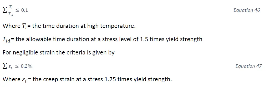
The NH criteria for negligible creep for displacement-controlled stresses are based on the idea that under maximum stress conditions, creep effects should not compromise the design rules for strain limits for creep-fatigue damage. The key consideration from that perspective is that the actual stress in a localized area can be much greater due to discontinuities, stress concentrations, and thermal stresses than the wall-averaged primary stresses in equilibrium with applied loads. Basically, the magnitude of the localized stress will be limited by the material’s actual yield stress because it is this stress level that the material will deform to accommodate higher stresses due to structural discontinuities or thermal gradients. Thus the objective of negligible creep criteria for localized stresses is to ensure that the damage due to the effects d creep and material’s yield strength will not significantly impact the design rules for the failure mode of concern. For e.g. there are two resulting criteria, one based on negligible creep damage and the other based on negligible strain. For negligible creep rupture damage, the III-NH criteria is given by [2]
In code case N-253, which provides elevated temperature design rules for Class 2 and Class 3 nuclear components, Appendix E contains a figure that shows time and temperature limits below which creep effects need not be considered in evaluating deformation-controlled limits. These curves are lower, smoothed versions of the Subsection NH criteria for negligible creep for a limited number of materials.
Summary
This write-up provides a broad overview of the phenomenon of creep and the way its approached in ASME codes, specially, ASME Boiler and Pressure vessel code SEC-III, Subsection NH. For additional details, interested readers should refer to [2] [3]. Reference [2] forms the basis of this write-up as well as sources of most figures and technical content used in this write-up. The topic of members under compression has not been discussed and details can be found in [2].
References
Mechanical behavior of materials, 4th Edition, Pearson, by Norman Dowling.
Design and analysis of ASME boiler and pressure vessel components in the creep range by Maan H. Jawad and Robert I.Jetter, ASME press, 2009.
ASME Boiler and Pressure vessel code SEC-III-Subsection NH
Creep of structures, by R.G.Sim, PhD dissertation, University of Cambridge, UK, 1968.
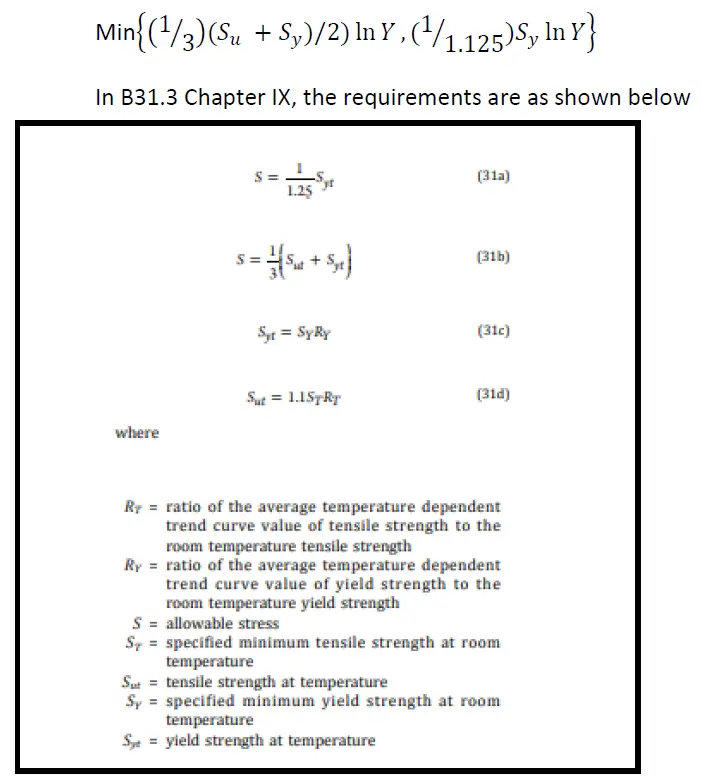
What is ASME B31.3 Chapter IX (High Pressure Piping)? Basis of Various Technical Requirements
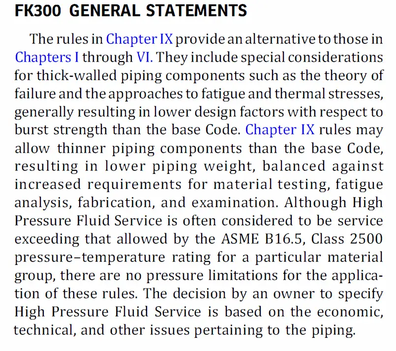
Chapter IX of ASME B31.3 is intended for use in high-pressure environments, but its use is not mandated beyond a certain pressure. In the words of the code (see [1]),
Figure 1- Intent of Chapter IX, ASME B31.3 [1]
[3] States that the rules of Chapter IX have been used in high-strength steels in pressure as low as 5000 psi.
There is often confusion amongst end users on the applicability of Chapter IX. An example being, can it be used for the analysis of flowlines? As stated in the wording of B31.3 Chapter IX, although the intended use of this chapter is for pressure-temperature combination exceeding that of ASME B16.5 pressure class 2500, but this is more of a rule of thumb than mandated use. A lower pipe wall thickness can be used if this section is utilized for designing piping systems intended for pressure classes less than ASME B16.5 2500#.
Chapter IX provides equations that are different from the base code for computing pipe wall thickness and a more conservative approach to the failure mechanism of Ratchetting (incremental plasticity). Testing/inspection and material requirements are also other aspects where this chapter differs from the base code. In this article, we will cover the technical background of some of Chapter IX’s specific requirements.
When and where to use Chapter IX, ASME B31.3?
A good rule of thumb is to use it for pressure-temperature combinations higher than that permitted by ASME B16.5 Flanges, but this standard can also be utilized for lower pressures to technically justify the use of lower pipe wall thickness than what is computed by base code or where there is concern for significant magnitude of pressure cycling. On this issue, system-specific experience is of paramount importance over any rule of thumb. One important point is to keep in mind that elevated temperature creep effects are not included in Chapter IX; thus, the use of Chapter IX is limited to temperatures below the creep regime for materials of construction [3].
Chapter IX also does not make any provision for Category D and Category M fluid service classifications. Considering the pressure, Category D is not applicable. There are no provisions for category M fluid service. Although the concept of severe cycling is not used in Chapter IX, but the stringency of the rules of this chapter makes additional consideration of severe cyclic service unnecessary [3].
What are the special considerations when dealing with suppliers for Chapter IX piping/pipe fittings?
As all materials are to be impact tested, it is essential to engage with suppliers at a much earlier stage of a project. It is also very important to ensure that the materials to be used shall be below the temperatures at which creep properties would govern the allowable stresses, and hence it’s very important to engage with suppliers to ensure the suitability of the supplied materials. This chapter follows the ASME Boiler and Pressure Vessel Code, Section IX for qualifications of welders or welding operators, however, there are additional requirements and limitations. This may require engagement with fabrication companies in an earlier stage of a project. Branch connection fittings are required to be designed to permit 100% radiography. General fabrication requirements pertaining to end preparation, alignment, welding, preheat, and PWHT are mostly similar to base code, with some variations [3].
The pitfalls of using Chapter IX
Higher engineering analysis costs (requiring engineering staff trained and experienced in using this chapter whose technical requirements are more rigorous than the base code), higher material testing (all materials are to be impact tested), examination, and leak testing are some concerns with the use of Chapter IX [6]. This chapter should only be used when the use of lower pipe wall thickness can be shown to be more cost-saving than the additional costs associated with materials, testing, and engineering.
Technical background to various requirements of Chapter IX
Pressure thickness equation and its technical background
The technical basis behind the wall thickness equation is shown in what follows.
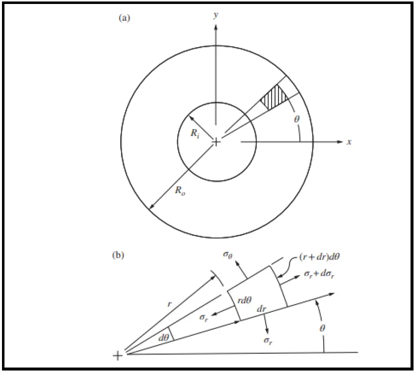
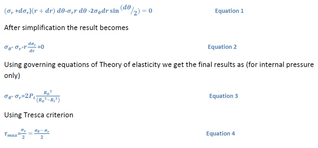
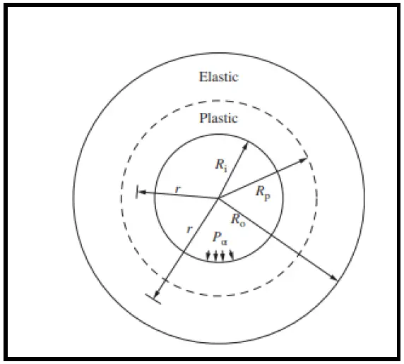
Figure 2- Free body diagram [4]
Summation of forces in 𝑟 direction gives
Figure 3- Plasticity zones [4]
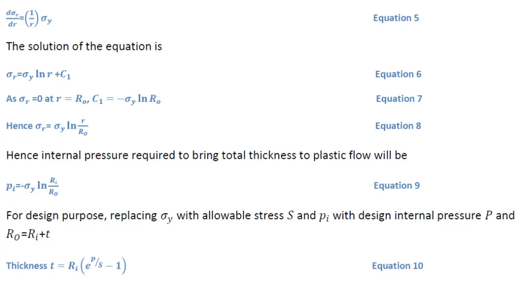
Using Tresca criterion,
It’s worth noting that ASME Boiler and Pressure vessel code SEC VIII D2 also uses the same form of equation.
Equations used in Chapter IX are
Figure 4- Pressure thickness equations [1]
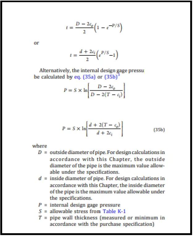
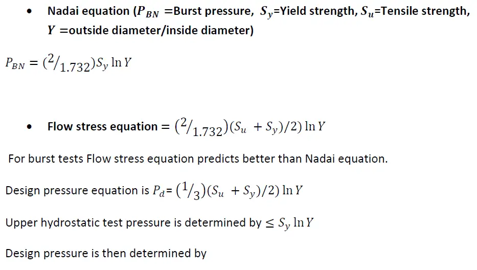
Closed-end cylindrical shell and burst pressure
The technical background requires an understanding of the development of ASME Boiler and Pressure Vessel code Sec VIII D3 as that forms the basis of the current edition of B31.3 Chapter IX. The development of Sec VIII D3 is in turn associated with the development of the Japanese High pressure vessel standard HPIS C106. We start with stating the Nadai equation and the Flow stress equation which are shown below.
Figure 5- B31.3 Chapter IX; Basis for allowable stresses
The issue of Fatigue analysis
Like the burst equations, Fatigue analysis of ASME SEC VIII D3 was also influenced by ASME V Boiler and Pressure Vessel code Sec VIII D3 which in turn was influenced by development of Japanese High pressure vessel standard HPIS C106. The main areas are highlighted and briefly discussed below.
Design fatigue curves for 17-PH
New design curves were developed [2] using test data and Manson’s modified universal slope equations. The new design curves for 17-4 PH were incorporated in ASME SEC VIII D3 in 2013 edition.
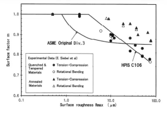
Surface roughness factors
Surface roughness affects high-cycle fatigue more than low-cycle fatigue. [2] Shows relation between surface roughness and surface factor which is defined as 𝜎𝑤/𝜎𝑤𝑜 where 𝜎𝑤= fatigue limit of arbitrary surface roughness and 𝜎𝑤𝑜=fatigue limit of maximum surface roughness less than 0.5𝜇𝑚.
Figure 6 Relation between surface roughness and surface factor [2]
Based on research work [2] on effect of surface roughness on annealed and Q&T (quenched and tempered) steels, it was observed that fatigue strengths for Q&T steels were affected more by surface roughness than Annealed materials. The fatigue limit of Q&T steels is inversely proportional to surface roughness. It is this work on surface factor which formed the basis of [2] and was subsequently incorporated in ASME SEC VIII D3.
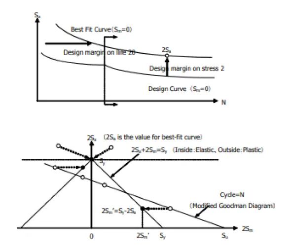
Mean stress correction procedure
Mean stress correction should be applied to best-fit curve and then the design curve should be developed. In the original (pre-2013 edition) of ASME SEC VIII D3 mean stress correction was used on the design curves. It was shown in [2] that the original version of ASME SEC VIII D3 showed much lower value of design life than the proposed method in HPIS C106. The reason for this discrepancy was the use of yield stress ( 𝑆𝑦) when mean normal stresses were calculated. To elucidate this point, Modified Goodman diagram from [2] is shown below. When design curve with design margin 2 on stress is used, 𝑆𝑦/2 instead of 𝑆𝑦 should be used for modified mean stress. In addition to this, when the proposed methods of HPIS C106 were compared with pre-2013 ASME SEC VIII D3, it was observed that ASME approach gave un-conservative results for compressive mean stress and conservative for tensile mean stress. While for some technicalities, details of which can be found in [2], ASME approach for compressive mean stress could not be changed in 2013 edition, but the approach for tensile mean stress based on HPIS C106 was introduced for non-autofrettaged vessels to take away excess conservatism.
Figure 7- Modified Goodman diagram [2]
Ratchetting
Unlike the base code, Chapter IX does not check the phenomenon of Ratchetting and fatigue using one equation and the equation for Ratchetting also does not allow for taking credit of liberal stress.
Figure 8-Check for Ratchetting Chapter IX B31.3 [1]
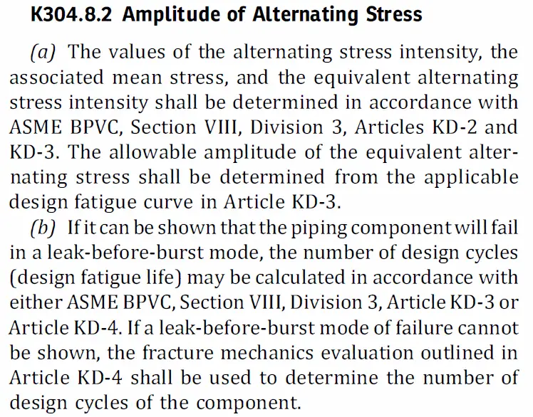
Figure 9 B31.3 Chapter IX latest requirements on Fatigue [1]
Hence, if leak-before-burst cannot be shown Fracture mechanics approach has to be used. The theoretical background behind “leak–before–burst” can be found in [5].
References
ASME B31.3 process piping code – 2022 edition.
Development of Japanese High pressure vessel standard HPIS C106 with ASME SEC VIII Division 3 – Susumu Terada, PVP 2017- 66082, ASME PVP conference July 2017, Hawaii, USA.
Process piping, the complete guide to ASME B31.3- Third edition by Charles Becht IV, ASME Press.
Stresses in ASME Pressure vessels, Boilers and Nuclear components – Maan H Jawad, ASME Press

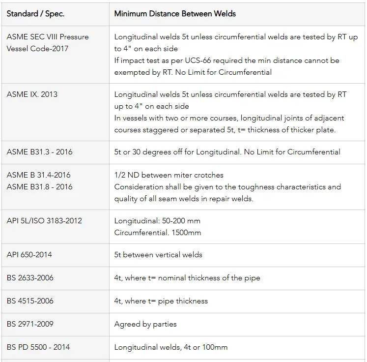
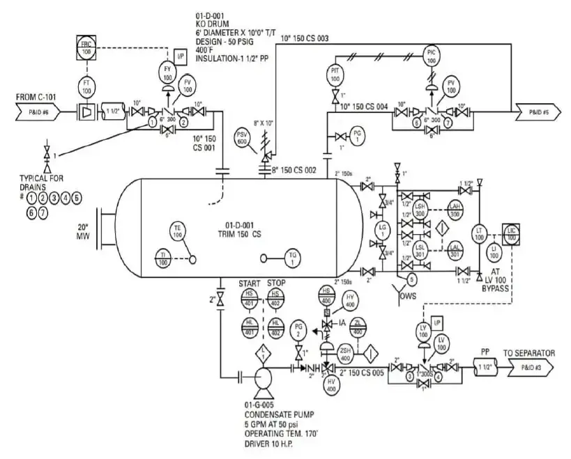
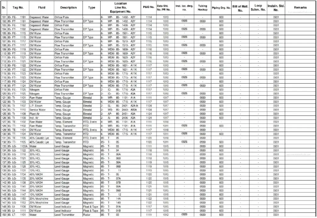
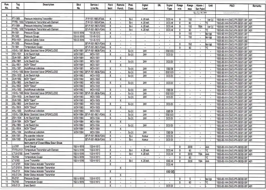
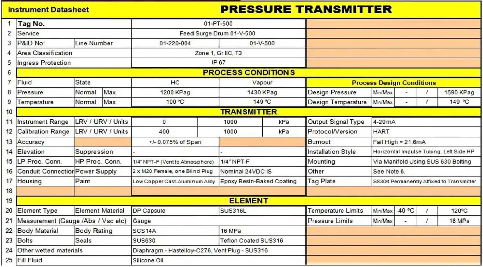
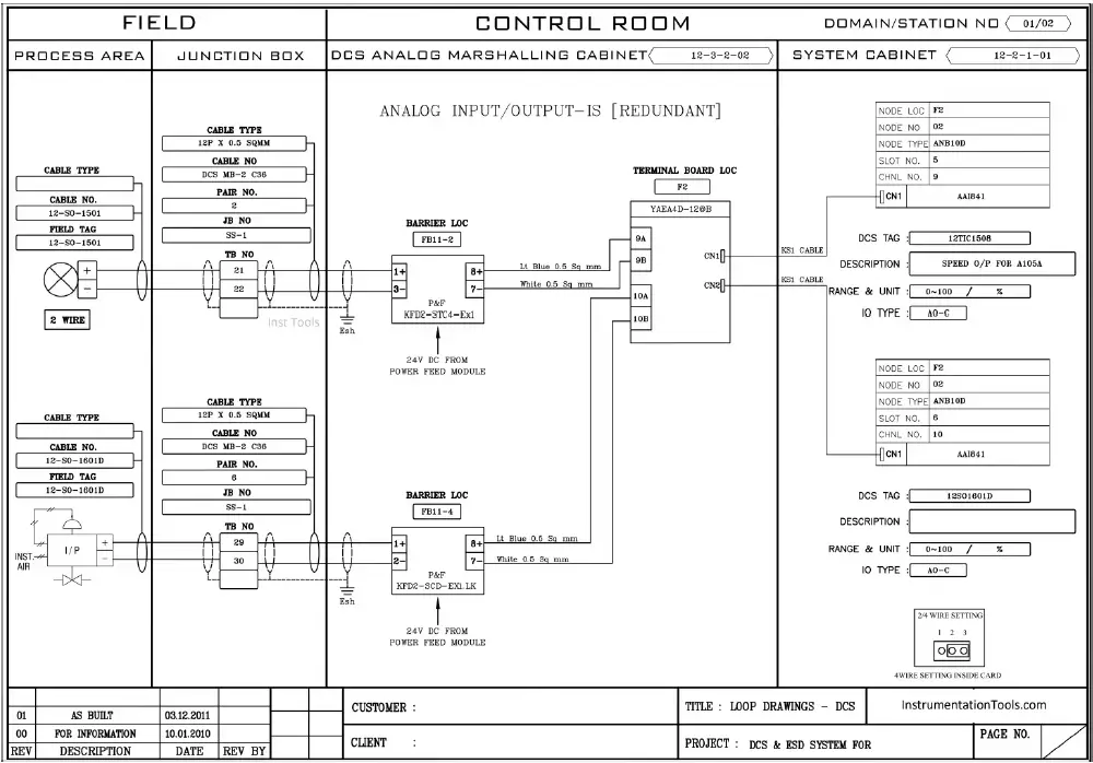
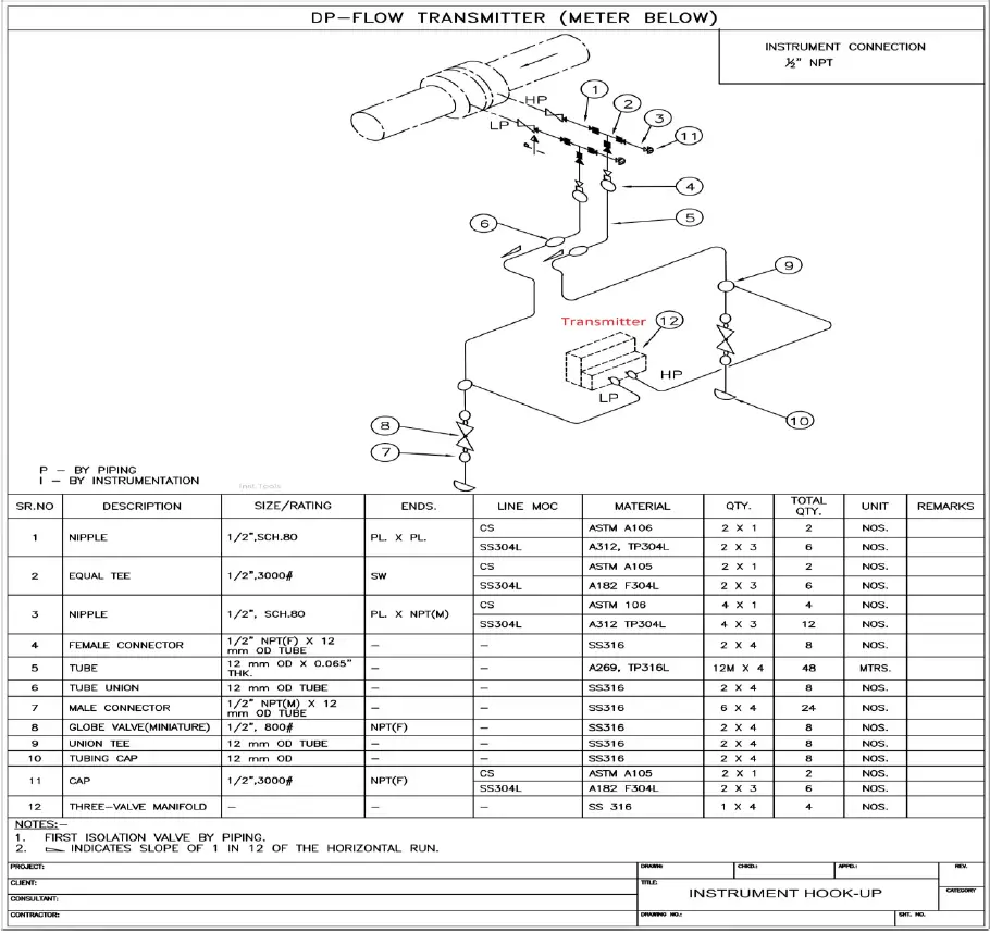
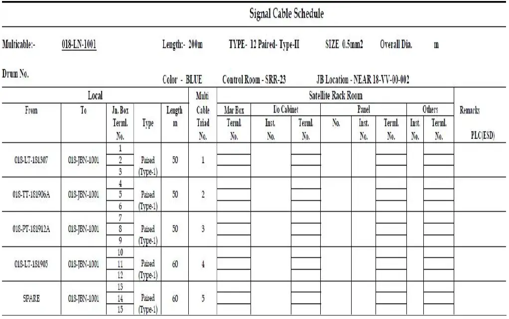
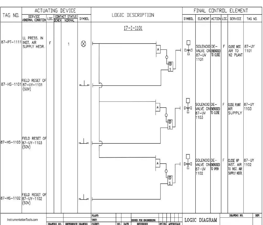
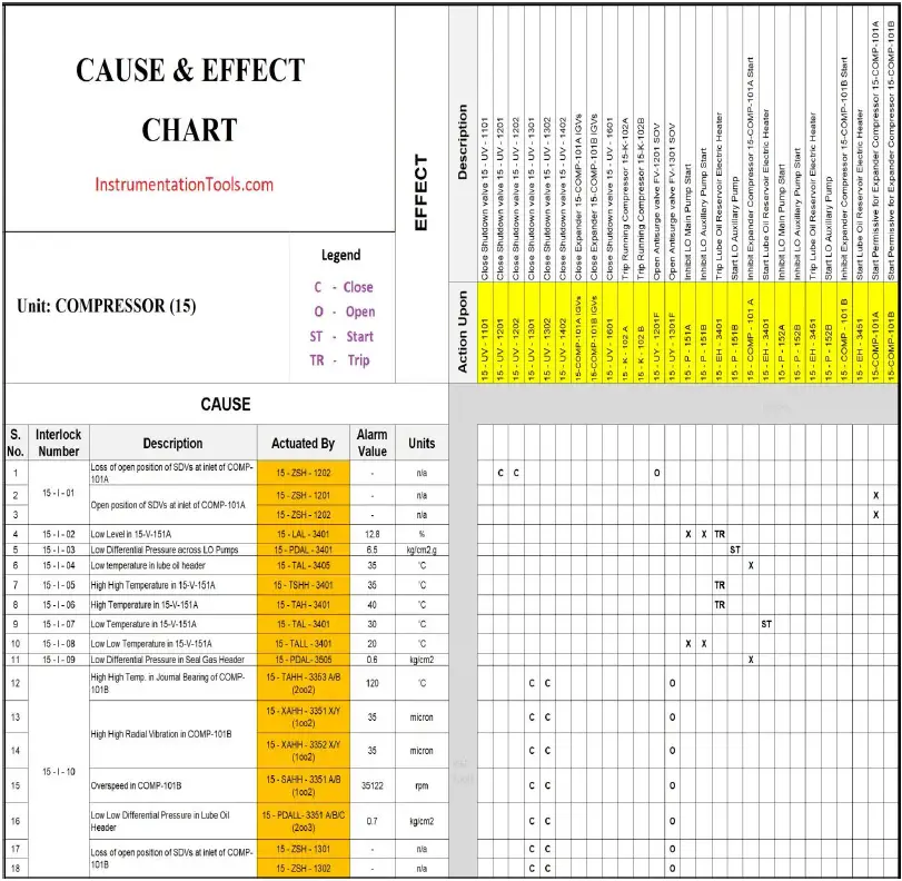


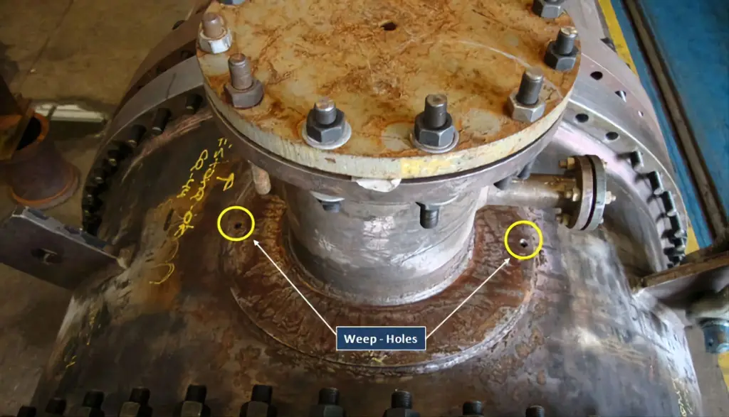
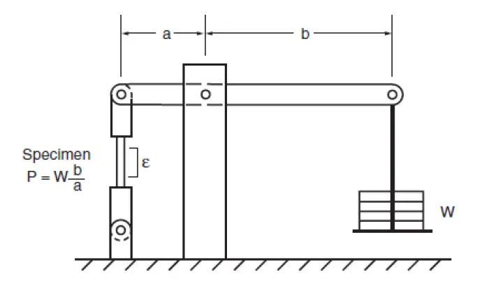
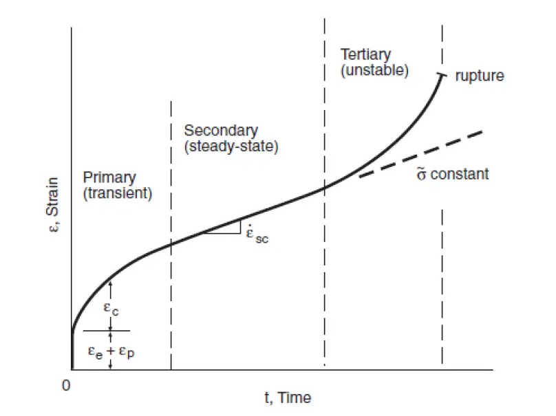
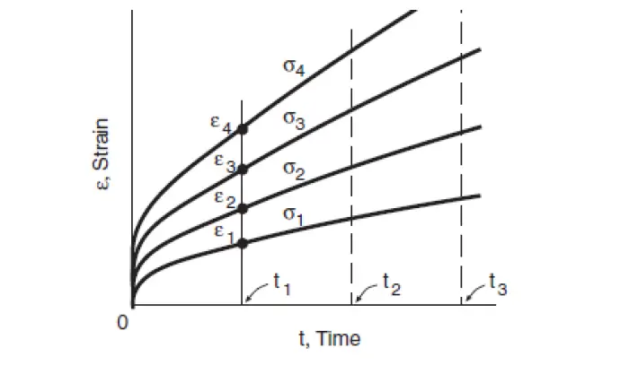
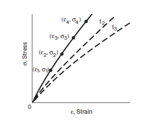
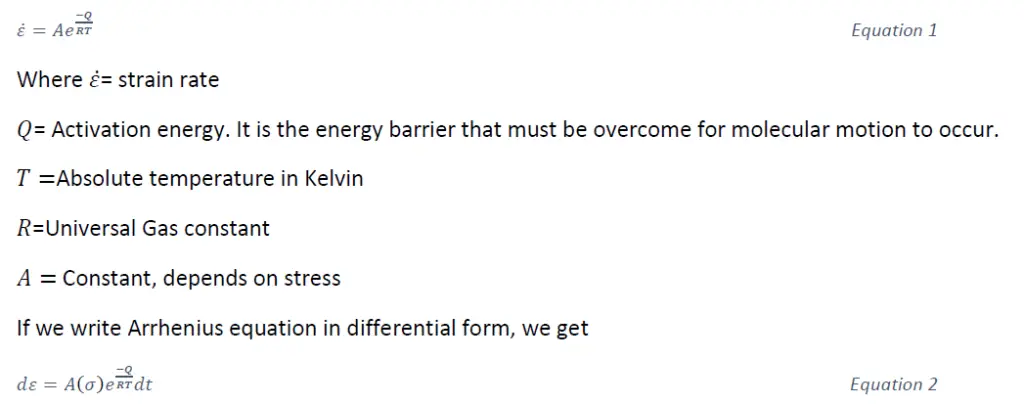
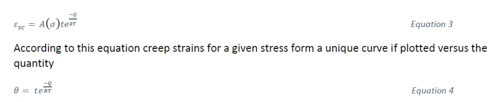
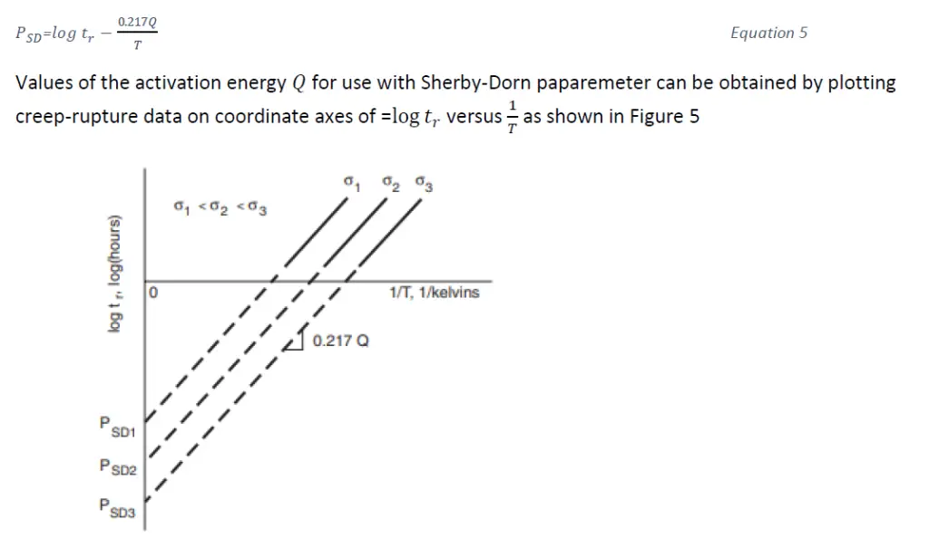
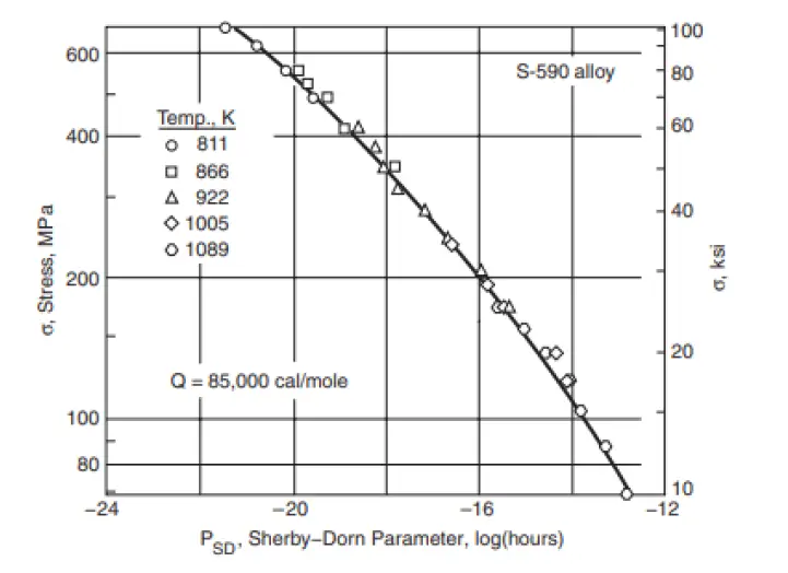
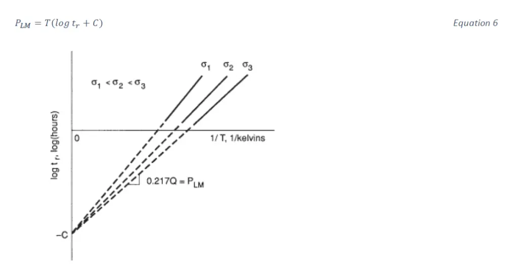
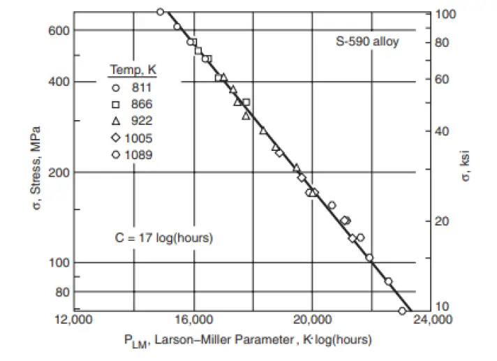
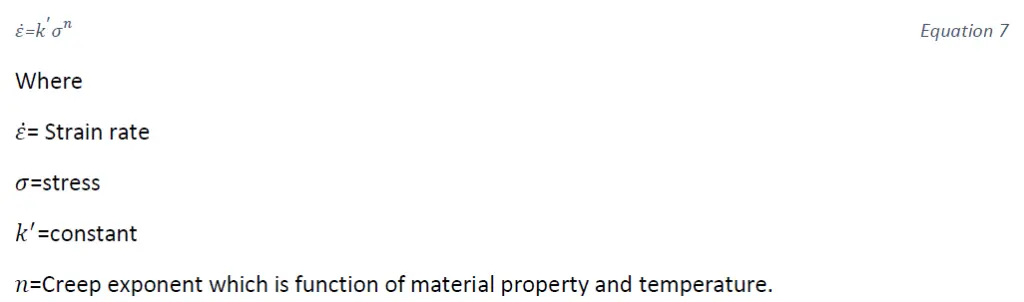
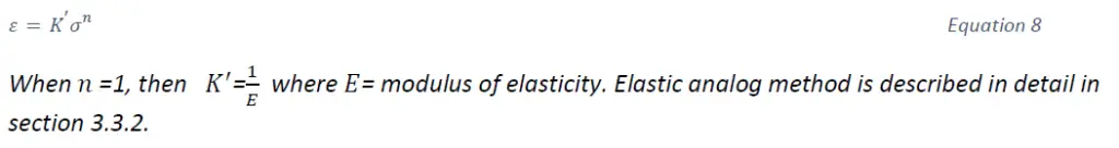

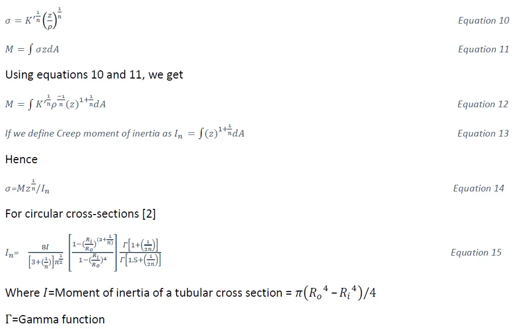
![Flow Diagram for Elevated temperature analysis NH-3221-1[2] [3]](https://whatispiping.com/wp-content/uploads/2024/11/image-52.png)
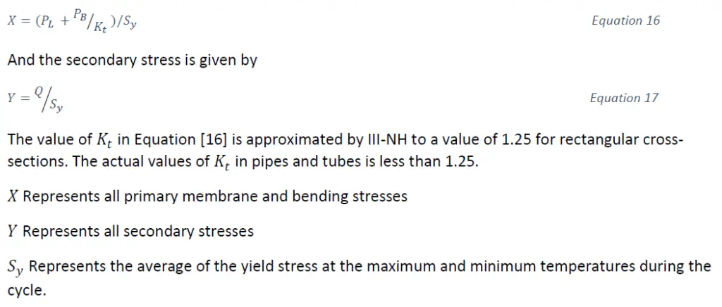


![Temperature limits [2]](https://whatispiping.com/wp-content/uploads/2024/11/image-58.png)
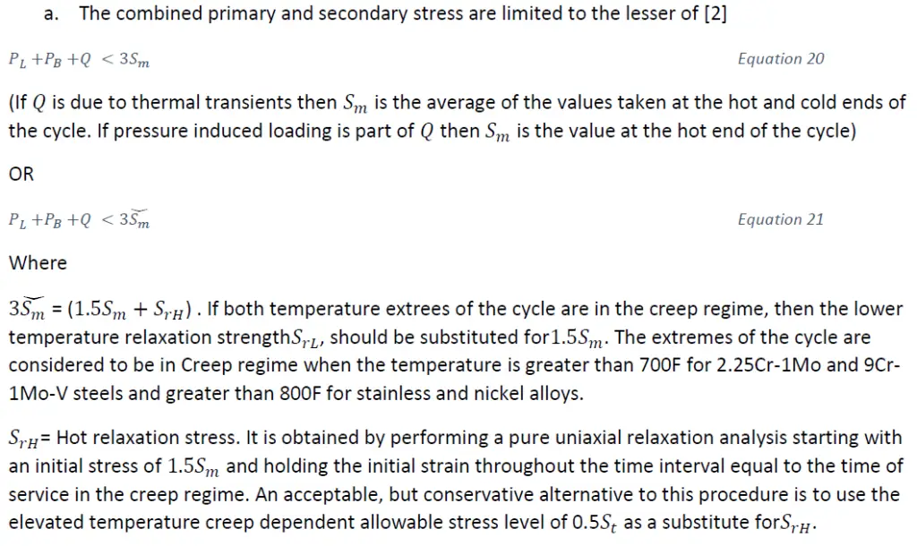
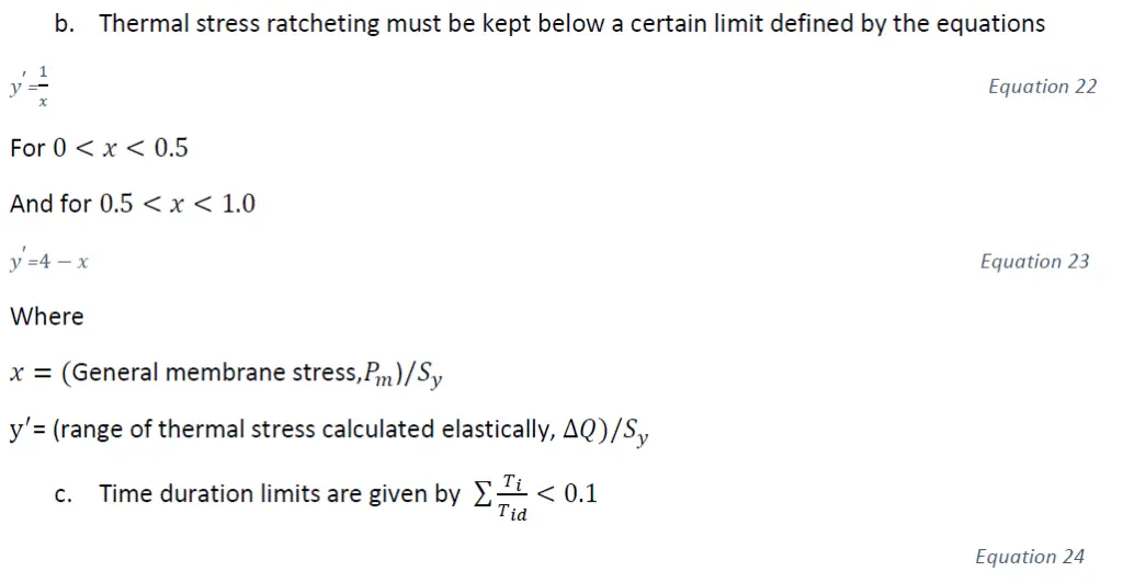
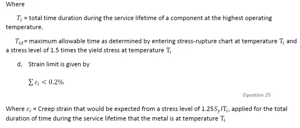
![Strain controlled limits-Elastic analysis [2]](https://whatispiping.com/wp-content/uploads/2024/11/image-66.png)
![Bree Diagram [2]](https://whatispiping.com/wp-content/uploads/2024/11/image-68.png)
![Effective Creep stress parameter Z for simplified inelastic analysis using test numbers B-1 and B-3(ASME-III NH) [2]](https://whatispiping.com/wp-content/uploads/2024/11/image-69.png)
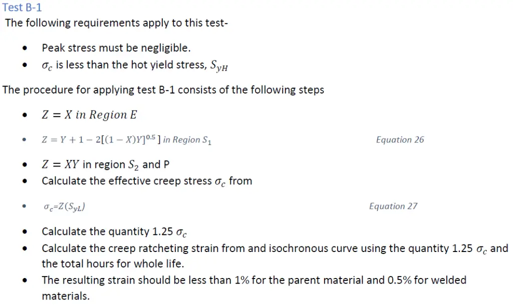
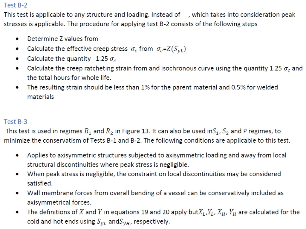
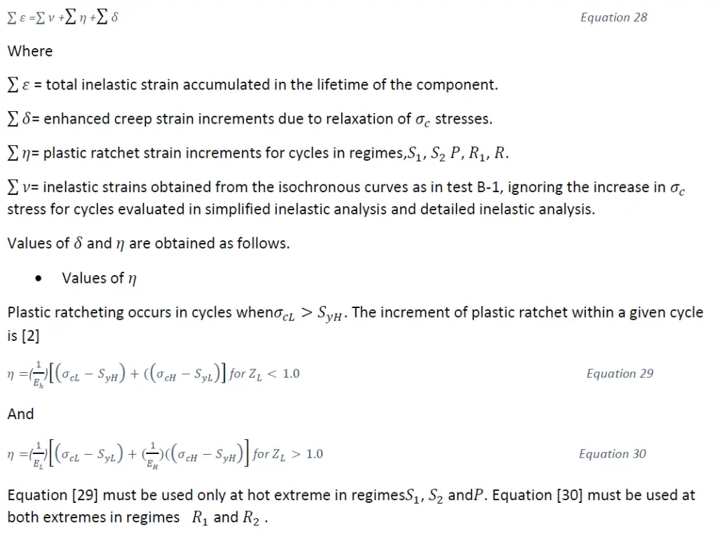
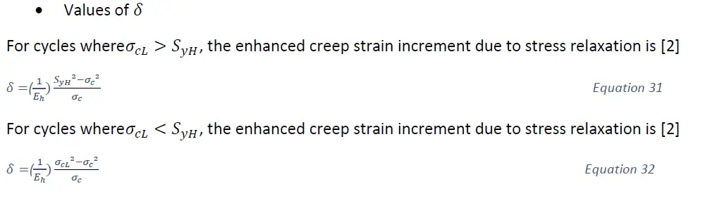
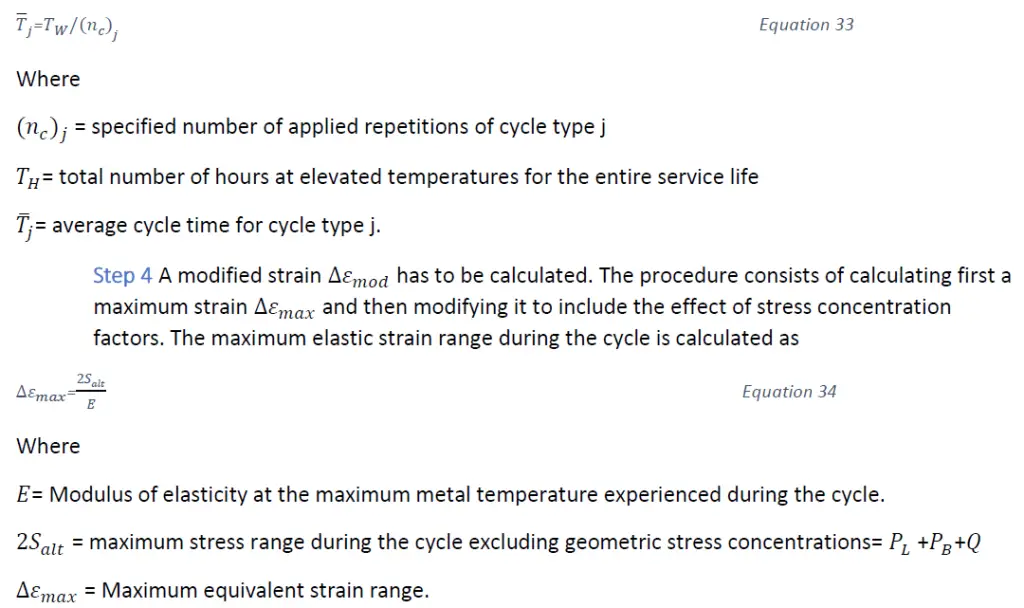

![Stress-strain relationship [2] [3]](https://whatispiping.com/wp-content/uploads/2024/11/image-76.png)
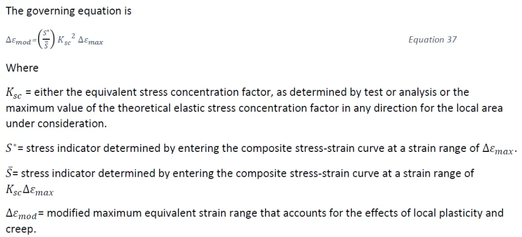
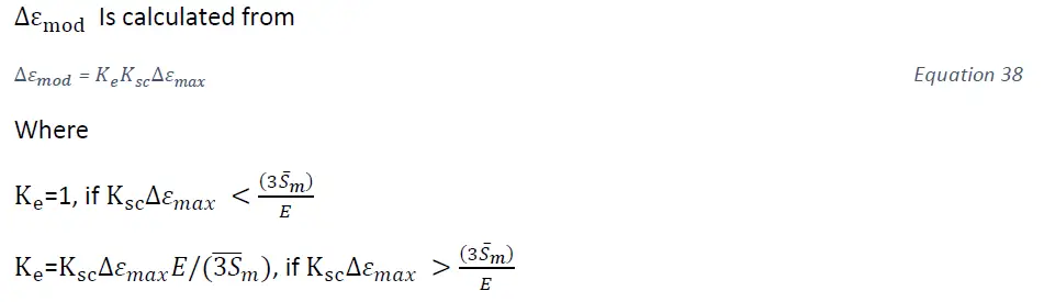
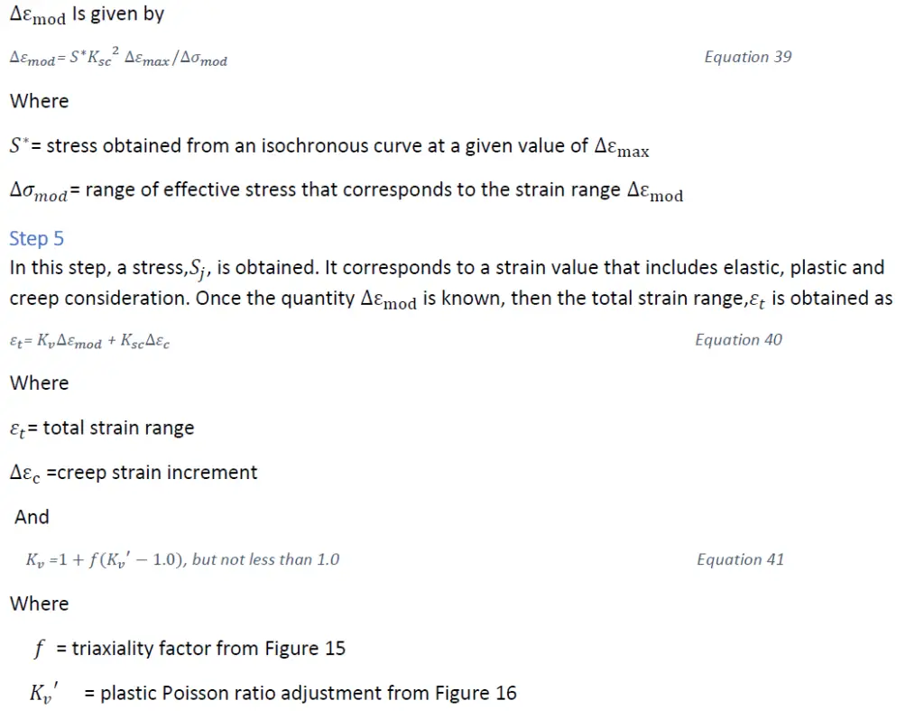
![Inelastic multi-axial adjustment [2] [3]](https://whatispiping.com/wp-content/uploads/2024/11/image-80.png)
![Adjustment for inelastic biaxial Poisson ratio [2] [3]](https://whatispiping.com/wp-content/uploads/2024/11/image-81.png)
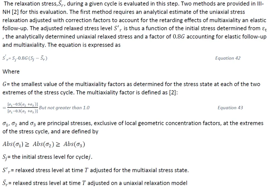
![A method of determining relaxation (ASME III-NH) [2] [3]](https://whatispiping.com/wp-content/uploads/2024/11/image-83.png)
![Stress -relaxation limits for creep damage (ASME III-NH) [2] [3]](https://whatispiping.com/wp-content/uploads/2024/11/image-84.png)
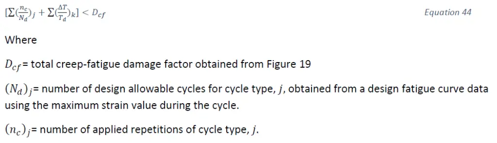
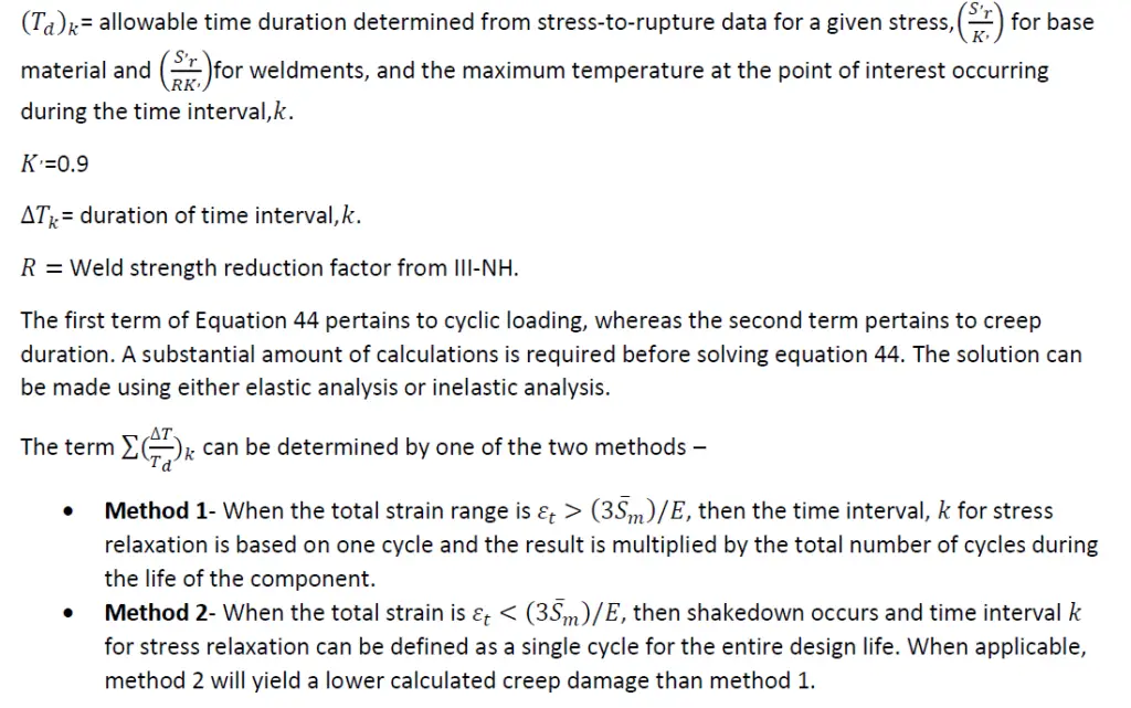
![Creep-fatigue damage envelop (ASME III-NH) [2] [3]](https://whatispiping.com/wp-content/uploads/2024/11/image-87.png)
![Steady state Creep stress distribution across a rectangular beam in pure bending [2]](https://whatispiping.com/wp-content/uploads/2024/11/image-89-1024x712.png)
![Creep Buckling Deflection-Time characteristics [2]](https://whatispiping.com/wp-content/uploads/2024/11/image-90.png)