
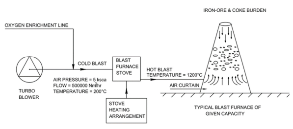
Steel is the backbone of the modern Construction industry. The biggest advantage of making anything in steel is that it is recyclable, cheap, and durable. Today, worldwide the most popular method of steel making is Blast Furnace – Basic Oxygen Furnace route or BF- BOF route. A Blast furnace (BF), is a type of metallurgical furnace used to produce industrial metals, generally pig iron. Blast refers to the combustion air, which is supplied at a positive pressure, into the Blast Furnace bottom with the help of Blast Furnace blowers.
The combustion air (first called cold blast) goes to the stoves where it gets heated to around 1200 Deg C ( after which it is called hot blast ) and then it enters the blast furnace through its bottom to create an air curtain which supports the whole Blast Furnace burden of coke, iron ore, limestone, etc ( charged from the top ) and allows the burden to drop down slowly from top to bottom so that proper combustion and reduction of iron ore can take place and liquid hot metal is produced. Oxygen enrichment of the cold blast is generally done in order to reduce the rate of consumption of coke in the Blast Furnace therefore increasing the overall energy efficiency of the plant. Dedicated Oxygen lines are laid from suitable tapping points in the plant Oxygen network up to the Cold Blast Headers for Blast Enrichment purposes.
The stepwise procedure for laying such an Oxygen pipeline considering the design parameters, site layout constraints, Finite Element Analysis Reports, pipe support selections, flexibility analysis, 3-dimensional pipeline drawing view preparation, etc are discussed briefly here.
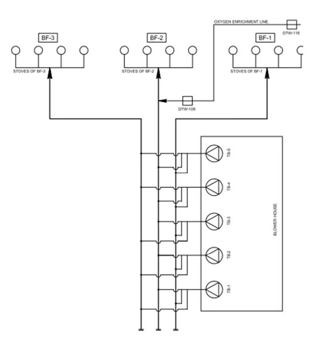
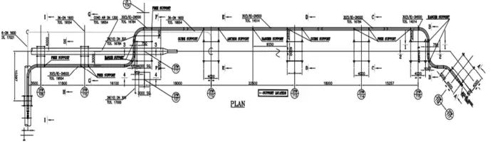
It is seen from the flow scheme in Figure 2, that five Turbo-blowers (TB-1 to TB-5) in the Blower
House generates the Cold Blast air which feeds all the three individual Cold Blast headers going to
BF-1, BF-2 and BF-3 respectively. The new DN 500 Oxygen enrichment line is also shown to be
tapped near tower DTW- 116 which is laid up to tower DTW 109 for discharging the enrichment
Oxygen on to the Cold Blast line there.
enrichment line going to BF-2 stoves
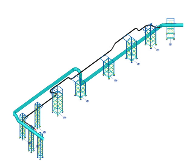
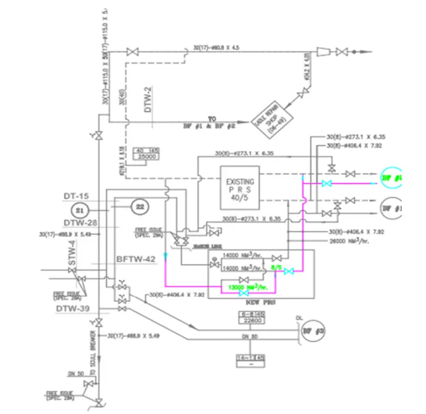
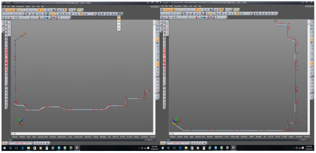
Figure. 4 shows the 3-dimensional view of the existing DN 1600 Cold Blast Line and the new
proposed DN 500 Oxygen line to be laid from DTW-116 to DTW-109. The bigger blue line is the
cold blast line and the black line below it is the Oxygen Line. The location of the towers/trestles
over which these lines are passing is also indicated in Figure 4.
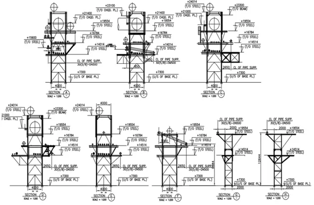
The Design Criteria for selecting these towers/trestles for laying the Oxygen pipe are explained in
brief as follows: –
- All available towers/trestles were designed way 30 years ago and were loaded to their maximum operating piping load. All free space in the towers/trestles was also exhausted by large and small diameter pipes at different racks of different elevations.
- Minimum clearance height had to be maintained from plant-finished ground level as per standard practice of Steel Plants. Hence the loading capacity of the towers/trestles was limited both in the up-down direction as well as in the sideways direction. Also, to cater to pigging operations, Oxygen pipelines are always designed with 5D long radius Bends which always take more space than other pipes.
- Pipe size cannot be reduced by increasing the velocity of flow. If velocity is increased, then firstly it can cause vibration which is undesired for old, rusted structures. Secondly, increased velocity leads to higher impingement velocity leading to pitting and faster erosion of the oxygen pipes.
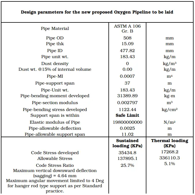
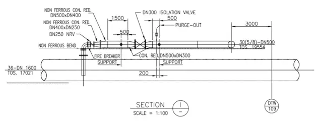
- Hence flow velocity in Oxygen pipelines is always restricted to 8 m/s. For optimization purposes, a pipe size of DN 500 was chosen and thickness was selected as per Schedule 40. For the bends, the pipe thickness was selected as per Schedule 80.
- The pipe support span was selected based on a maximum vertical deflection of 2.5 mm. Based on this pre-condition, the maximum span limit is found to be 11.02 m. Design pressure is taken as 500 KPa. The design temperature is taken as 60 degrees C. 7000 cycles are considered for this pipe as the failure limit.
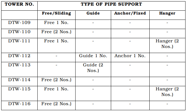
To provide the supports for the new DN 500 Oxygen pipe from existing old, rusted towers/trestles
(which were packed with other service pipelines) was difficult.
Hence the route had to be reviewed to find out the suitable locations/elevations of the structure from where new structural members could be erected considering the stability of both the existing structures and the new pipe. After a thorough study, the route from DTW-116 to DTW-109 was chosen. Here the location/ route layout of the new pipe is mainly guided by the availability of free space in pipe racks over towers/trestles where new pipe supports could be provided.
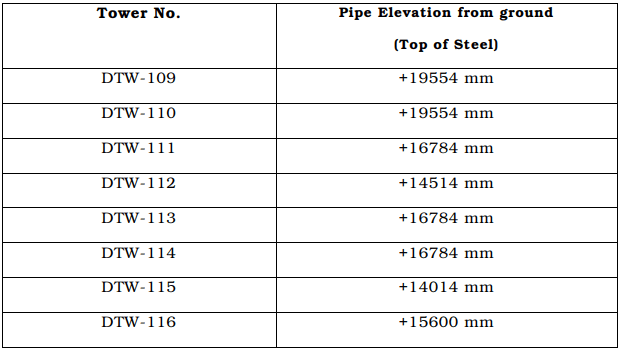
Elevation of the new pipe continuously changed throughout its course while moving from DTW-116 to DTW-109 as indicated in Table 2.
The ups and downs of pipe routing were used for the flexibility of the piping. Hanger supports were provided at some portions of the pipe routing for the following reasons: –
- It was impossible to provide Structural members at those elevations.
- To reduce the axial load at those structures that were within the permissible values of the operating load.
The theories of failure as considered – “Maximum Shear Stress Theory” and Piping Code
followed is ANSI B31.3.
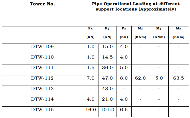
The Design Results for this application have been shown in various preceding tables and figures of the current paper. The physical condition of the entire Oxygen piping system after commissioning has tallied well with the obtained design results. The DN 500 Oxygen Pipe for Cold Blast Enrichment has been successfully commissioned and has been in operation for the past year. All the design objectives are fulfilled and the DN 1600 Cold Blast Line is enriched with Oxygen.