
The stress analysis methodology of air cooler piping is quite different from other types of heat exchangers. This is mainly due to its different construction and supporting arrangements. The principal application of an air-cooled heat exchanger is to maintain a heat balance through the addition or removal of heat between streams of two different operating temperatures. Air fin cooler (AFC) or air cooler uses the air stream as the cooling medium. Air is circulated by multi-blade propeller-type fans as heat exchanger media. AFC unit consists of fin tube bundles with a header box attached to each end, supported horizontally by a C-shaped steel frame or structure. In the following paragraphs, we will explore the stress analysis philosophy of air cooler piping systems using Caesar II.
Documents for Air Cooler Piping Stress Analysis
The important documents required for the stress analysis of air-cooled heat exchanger piping are
- Latest piping stress isometrics.
- Line Designation Table or Line List
- P&ID or PEFS
- The latest revision of equipment GA drawing (covering all dimensions, Materials, nozzle allowable, and weight of AFC)
- Allowable nozzle load (API 661 tables can be used in absence of vendor allowable loads if the air cooler is designed as per API 661)
- Mechanical datasheet (Optional).
Stress Analysis with known Displacement of Air Fin Cooler From Vendor
If the vendor gives a thermal displacement value in the air cooler GA drawing then with the known value of displacements we can analyze the system. At the piping flange connecting the equipment nozzle enter the value of DX, DY, and DZ value in displacement vector -1, keeping RX, RY, and RZ values zero.
This is the most simple type of analysis and In this case, there is no need to model the air cooler in CAESAR II. However, in most situations, the displacements are not available. So, the stress analysis engineer has to model the equipment by taking data from the GA drawing.
Modeling air cooler in Caesar II
Modeling up to the top or bottom of the header
- Model pipe up to matching flange of piping and AFC nozzle as per the given stress isometrics.
- From the equipment GA drawing, model as per dimensions given up to the top or bottom of the header with proper thickness and size of the nozzle.
- Provide a C-node anchor at the junction of the header and inlet or outlet nozzle.
Modeling part after defining the c-node anchor
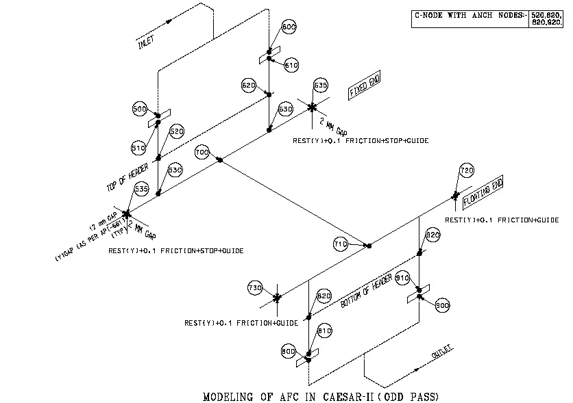
- As per Fig-1, define 520 and 620 both as ANCHOR nodes with C-node as 521 and 621 respectively for checking of nozzle load.
- Model equipment parts from nodes 521 to 530 and 621 to 630 as rigid elements with the same temperature of piping up to the centerline of the header without weight.
- Then model header as node numbers 530 to 535, 630 to 635, and 530 to 630 with weight and temperature the same as piping (15 percent of total empty weight, total weight between 535 to 635).
- Break the element 530 to 630 giving node 700 half of its length.
- Model tube bundle with node 700 to 710 (rigid element) as per its length given in GA drawing with weight (70 percent of total empty weight) and give supports REST+ PTFE (0.1 FRICTION) at every one-meter distance along the bundle length.
- Model 710 to 715, 715 to 720, 710 to 725, and 725 to 730 nodes as header elements with weight and the same average temperature of inlet and outlet. (15 percent of total empty weight, distribute in these two nodes).
- Model 715 to 921 and 725 to 821 rigid elements without weight taking an average of inlet and outlet temperature of piping. (921 and 821 are C-nodes).
Modeling Part Of Equipment Restraint Nodes (Fixed Header)
- The whole AFC has been supported at four ends on PTFE (Teflon) pad.
- One header act as a fixed and the other as a floating end.
- See vendor drawing for defining support nodes as fixed or floating.
- As per Fig-1, the north side header (nodes 525 to 635) is fixed and hence south side header (nodes 720 to 730) is a floating end.
- Define fixed-end nodes 535 and 635. Give Rest (Y) support with 0.1 friction coefficient, Axial stop (X) North-south directional stop with 2 mm gap, and Guide (Z) East-West with standard 12mm gap as per API 661 at both nodes.
- Define floating end nodes 720 and 730. Give Rest (Y) support with 0.1 friction and Guide (Z) East-West with a standard 12mm gap as per API 661 at both nodes.
Note: The guide gap can be increased as per the lateral thermal movement of the Air fin cooler to avoid excessive nozzle load. Practically for that slot, the length can be increased after approval of the equipment department and vendor.
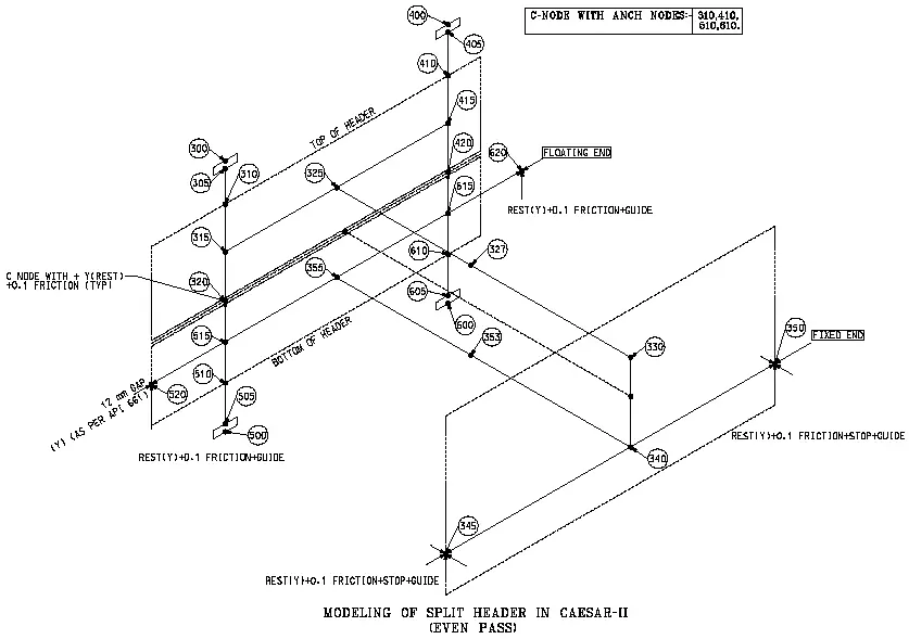
Modeling Part After Defining C-Node Anchor (Split Header)
Split header case modeling in CAESAR-II, is described below:
- As per Fig-2, define 310 to 410 both as ANCHOR nodes with C-node as 311 and 411 respectively of inlet nozzle and 510 and 610 are of outlet nozzle as C-nodes 511 and 611 for checking of the nozzle load.
- From C-nodes 311 and 411, model up to the centerline of the upper header in split header case as rigid elements 311 to 315 and 411 to 415 without weight but with an average of inlet and outlet temperature.
- Then model half depth of top header elements as 315 to 320 and 415 to 420.
- The top header will rest on the bottom header with a Teflon pad so define nodes 320 and 420 as +Y with 0.1 friction and C-node as 321 and 421.
- Model 315 to 325 and 325 to 415 as a rigid element with half of the distance between two inlet nozzles with the half weight of one header and average temperature (Distribute the weight in 315-325 and 325-415).
- Model 325 to 330 as a rigid tube bundle element with a length of bundle given in the drawing and provide supports along the length.
- Model elements 330 to 340 as rigid elements with the distance between two header center lines without weight.
- Model 340 to 345 and 340 to 350 as fixed header elements with the half weight of the total header weight.
- Model elements 340 to 355 as connecting tubes to the bottom header with an average temperature of inlet and outlet and half of the weight of the tube bundle.
- Model node numbers 355 to 515, 515 to 520, and 355 to 615, 615 to 620 as rigid elements indicating a lower header with the proper distance from GA and half of one header weight.
- Model node number 321 (C-node) to 515 and 421 (C-node) to 615 as half of the depth of the lower header without weight.
- Model elements 515 to 511 and 615 to 611 as rigid elements as half of the depth of the lower header.
- Model bottom nozzle part and give 510 and 610 as ANCHOR with C-node restrain as 511 and 611.
Modeling Part of Equipment Restraint Nodes (Split Header) is as follows:
- Defining of restraint for the fixed and floating end will be the same as mentioned in the fixed header case.
- Here in Fig 2, nodes 345 and 350 are support nodes of the fixed end whereas nodes 520 and 620 are support nodes of the floating end.
- There is only one extra support between two split headers at nodes 320 and 420 which are +Y with 0.1 friction coefficient and C-node as 321 and 421.
Next, create the load cases in a similar way for all other equipment and check the output results for consistency with respect to codes and standards. Air cooler nozzle loads are qualified with API 661 table values in absence of vendor-given allowable loads.
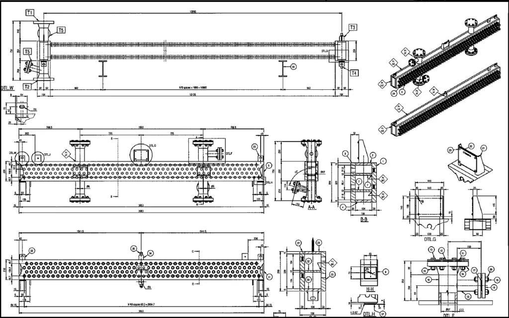
Fig. 3 below shows a typical GA drawing of an air cooler.
To know more about Air Cooler heat exchanger click here and to know about Air Cooler connected Piping Design Click here.
This is nice that you have started your experience in the form of papers. In this process you will get feed back. At the end of the day accurate modeling is one part, other part is accurate transmission of load being generated which is acceptable by Civil for structure. Congratulations for initiatives.
Thanks a lot.
It seems that average temp. in many parts is’nt accurate enough.
HELLO
YOUR DESCRIPTION ABOUT MODELING AIR COOLER IN CAESRII WAS VERY TECHNICAL. ALTHOUGH
I GOT ENOUGH INFORMATION I NEED A VIDEO HOW EXPERIENCED ENGINEERS MODEL AIR COOLER IN CAESARII. BECAUSE I DONT HAVE MUCH EXPERIENCE IN THIS FIELD. PLEASE SEND IT FOR ME.
THANKYOU IN ADVANCED.
As per API 661
7.1.1.2 The Vendor shall make provision for lateral movement of exchanger tube bundles of at least
6 mm (1
/4 in.) in both directions or 12.7 mm (1
/2 in.) in only one direction, unless the Purchaser and the
Vendor agree on a different value.
Keep these lateral movement as per API 661 instead of giving gap 12 mm because there clearly stated.
As per API 661
7.1.1.2 The Vendor shall make provision for lateral movement of exchanger tube bundles of at least
6 mm (1
/4 in.) in both directions or 12.7 mm (1
/2 in.) in only one direction, unless the Purchaser and the
Vendor agree on a different value.
Instead of giving 12 mm gap please note above from API 661.