
What is a Flare System?
As per CAPP – Canadian Association of Petroleum Producers, a flare system is defined as the controlled burning of natural gas that cannot be processed for sale or use because of technical or economic reasons.
On the Other hand, API 537 defines a flare system as the system provided in a refinery or petrochemical plant to ensure the safe and efficient disposal of relieved gases or liquids.
The efficient flaring system exists at any facility accommodating Hydrocarbon pressurized systems such as:
- Refineries.
- Natural gas processing plants.
- Petrochemical plants.
- Wells / Rigs.
- landfills.
Application of Flare System
Flares are primarily used for burning off flammable gas released by pressure relief valves during any over-pressure scenario of plant process unit/equipment, due to process upset or during startups & shutdowns, and for the planned combustion of gases over relatively short periods.
Flare systems are used for a variety of activities such as:
- Normal Operation (as defined above).
- Startup.
- Maintenance.
- Testing.
- Safety and emergency purposes.
Features of Flare System
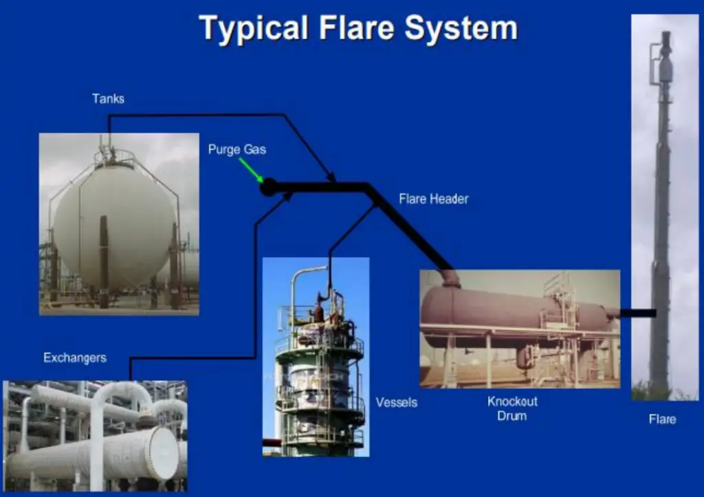
Fig. 1 shows a typical flare system in a process plant. The important features of a flare system are
- When any equipment in the plant is over-pressured, the pressure relief valve is an essential safety device that automatically releases gases and sometimes liquids.
- The height of the flame depends on the volume of released gas, while brightness and color depend upon composition.
- The released gases and liquids are routed through large piping systems called flare headers to the flare. The released gases are burned as they exit the flare stacks.
- Commonly, flares are equipped with a vapor-liquid separator (also known as a knockout drum – KOD) upstream of the flare to remove any large amounts of liquid that may accompany the relieved gases to avoid fireballs.
- Steam is very often injected into the flame to reduce the formation of black smoke.
- When too much steam is added, a condition known as “over-steaming” can occur resulting in reduced combustion efficiency and higher emissions.
- To keep the flare system functional, a small amount of gas is continuously burned, like a pilot light, to assure that the flare system is always ready for its primary purpose as an over-pressure safety system.
When does a Flaring Incident Take Place?
The flaring system is normally activated during the following situations
- Initial startup.
- Poor reliable plant / old.
- Planned maintenance / Projects / Shutdown activities.
- Process upset led to overpressure scenarios.
- Emergency situation.
Gas Flaring Composition
There is in fact no standard composition and it is, therefore, necessary to define some group of gas flaring according to the actual parameters of the gas.
- For NGL & LNG plants, the flared gas composition is expected to be 80 – 90 % C1 & balance is C2+ & Inert gases such as N2 and CO2.
- Gas flaring from refineries and Petrochemical plants will commonly contain a mixture of paraffinic & Olefinic HC, inert gases, and H2.
- In landfill gas & biogas plants, the flared gas composition is a mixture of CH4 and CO2 along with small amounts of other inert gases.
- Note: Changing gas composition will affect the heat transfer capabilities of the gas and affect the performance of the measurement by a flowmeter.
Flare system components
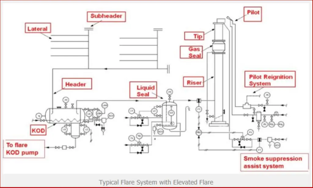
Fig. 2 below shows a typical flare system with elevated flare. The important flare system components are marked in the image.
Types of Flares
- Vertical
- Self Supported.
- Guyed (Cables).
- Derrick supported (Steel).
- Horizontal
- The flared fluids are piped to a horizontal flare burner that discharges into a pit or excavation.
- Enclosed Flame Flares
- They are designed to conceal flares from direct view, reduce noise, and minimize radiation.
All the above flare types can be either single-point or Multi-burner staged flares. Also, Flares can be classified as either
- smokeless (using air, steam, pressure energy, or any other means to create turbulence and entrain air within the flared gas stream ) or
- Non-smokeless flares (used when smoke isn’t a concern or the flared fluid doesn’t generate smoke such as H2, NH3, H2S…etc).
Flare System Selection Considerations
The Flare system is normally selected based on the following considerations.
- Safety requirements and environmental regulations must be satisfied.
- CAPEX & OPEX.
- Gas process conditions and properties.
- Neighborhood relationships, availability, and cost of utilities.
- Space availability.
Flaring Environmental impacts
- The global warming potential of Methane is estimated at 34 times greater than that of CO2. Therefore, by converting the methane to CO2 before it is released into the atmosphere, the amount of global warming is reduced. However, flaring emissions contributed to 270 Mt CO2 in 2017, and reducing flaring emissions is key to avoiding dangerous global warming.
- Improperly operated flares may emit methane and other volatile organic compounds as well as sulfur dioxide and other sulfur compounds, which are known to cause respiratory problems.
- Emissions from improperly operated flares like aromatic hydrocarbons (benzene, toluene, xylenes) and benzo(a)pyrene, etc. are known to be carcinogenic.
- It is now recognized as a major environmental problem, contributing an amount of about 150 billion m3 of natural gas that is flared around the world, contaminating the environment with about 400 Mt CO2 per year.
Gas Flaring Reducing and Recovery (R&R)
There are many types of FGRS (Flare Gas Recovery Systems) in the industry:
- Collection, compression, and injection/reinjection
- Generating electricity by generation and co-generation of steam and
electricity
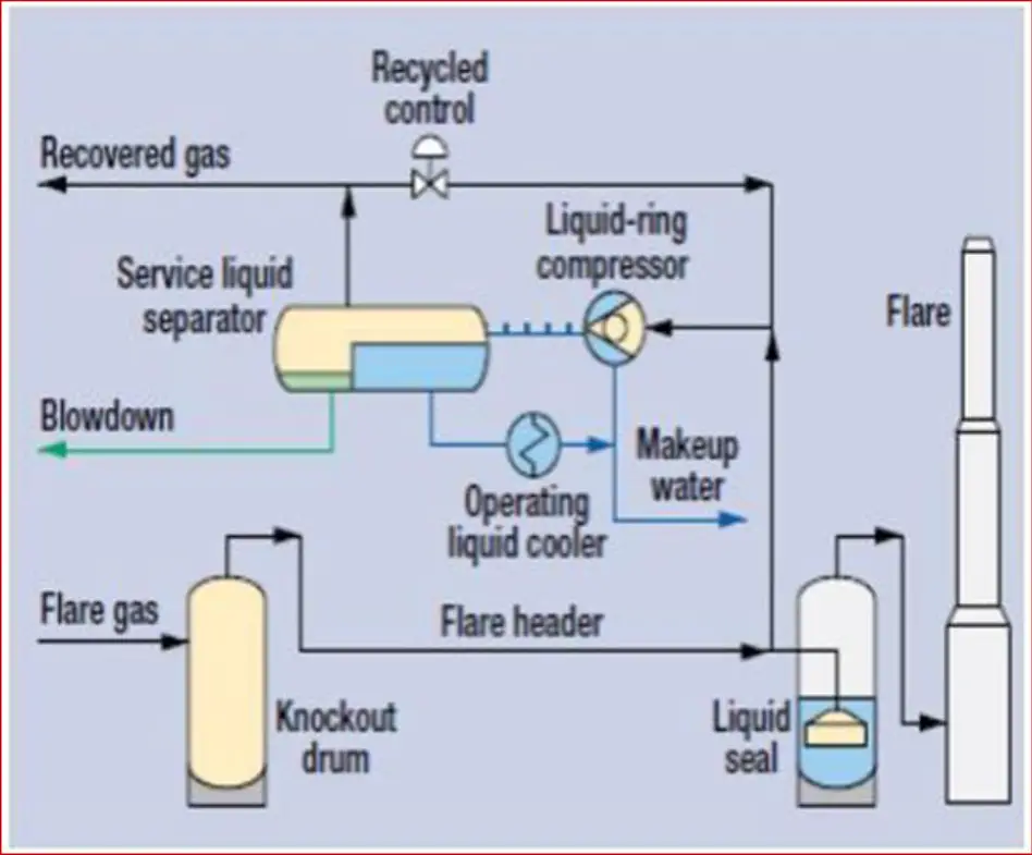
The gas collection and compression into pipelines for processing and sale is a well-established and proven approach to mitigating flaring and venting. According to environmental and economic considerations, FGRS has increased to reduce noise and thermal radiation, operating and maintenance costs, air pollution, and gas emission, and reduces fuel gas and steam consumption. Fig. 3 below shows a typical example of a flare gas recovery system.
Flare System Design
API 537 is used for flare system design. This standard is applicable to Flares used in pressure-relieving and vapor-depressurizing systems used in General Refinery and Petrochemical Services. Although this standard is primarily intended for new flares and facilities, it may be used as a guideline in the evaluation of existing facilities together with appropriate cost and risk assessment considerations. API 537 must be referred to in consideration with
- API RP521 (Guide for Pressure-Relieving and Depressurizing systems), and
- API 560RP2A (Fired Heaters for General Refinery Service Recommended Practice and constructing fixed offshore platforms).
Factors Affecting Flare System Design:
Design factors that influence the flare system design are:
- flow rate;
- flare gas composition;
- flare gas temperature;
- gas pressure available;
- utility costs and availability;
- safety requirements;
- environmental requirements;
- social requirements.
The plant owner or the plant designer must provide these factors to define the flaring requirements.
A. Flare System Design Criteria
The prime objective of a flare system design is safe, effective disposal of gases without compromising appropriate design considerations like:
- Reliable effective burning to reduce emissions to the permitted level.
- System hydraulics shall be sufficient to deliver all of the waste gas and auxiliary fuel gas, steam, and air to the flare burner with sufficient exit velocities. System pressure cannot exceed the maximum allowable operating pressures at any active relief source, vent, or utility supply.
- Liquid shall be removed sufficiently to prevent poor combustion, burning liquid droplets, and clogging the flare burner.
- Air infiltration should be avoided using a proper seal system to avoid internal combustion within the riser and flashback in the flare header.
- Flame radiation should be controlled within admitted limits to avoid nearby property damage or personnel injury.
- A smoke suppression system, if required, should ensure Zero smoke operation.
- Flare gas recovery system feasibility to be assessed to enhance plant efficiency and eliminate flaring incidents.
B. Flare Header Sizing
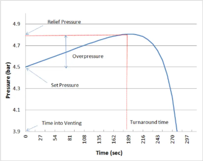
The take-off point for flare header sizing is to have a proper relief load calculation based on the worst credible scenario, where the pressure will increase until a predetermined relief pressure is reached, at which point the relief pressure valve will open, decreasing the pressure after the turnaround time. Refer to Fig. 4.
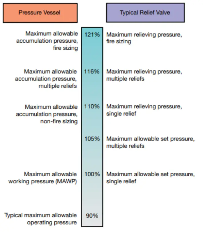
ASME Boiler & Pressure Vessel Code VIII Guideline For overpressure protection Requirements:
The ASME Boiler and Pressure Vessel Code Sec VIII sets out requirements for standard pressure vessels (left) and the relief valves (right) protecting them as a percentage of the maximum allowable working pressure (MAWP) as shown in Fig. 5.
Relief Valve Sizing Procedure
Refer to Fig. 6 below which shows a typical flowchart explaining the steps for the relief valve sizing procedure.
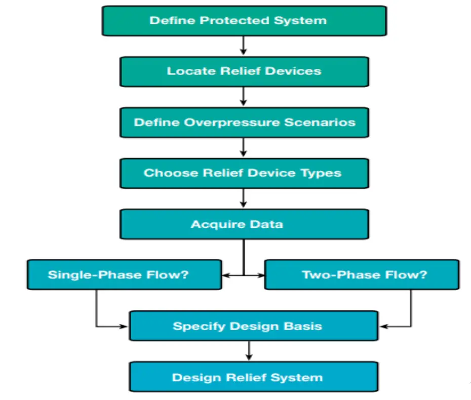
Fig. 7 below shows a typical flare header system for a processing plant.
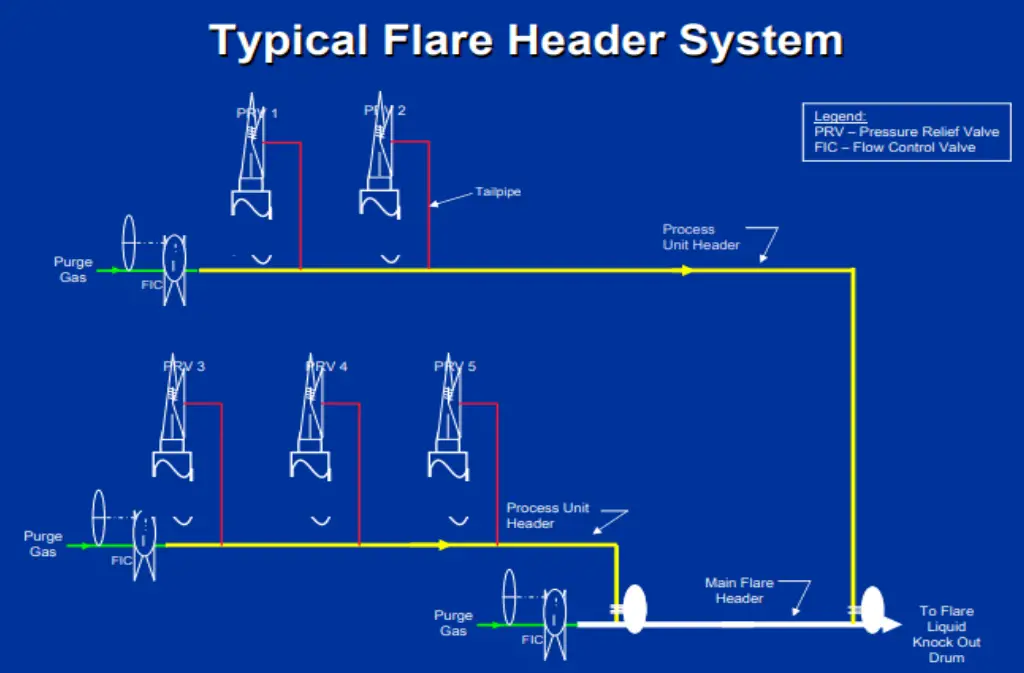
- Low-pressure pipe flares are not intended to handle liquids. Also, they do not efficiently perform when there is a liquid hydrocarbon release into the flare system.
- Backpressure and Gas Velocity are the major criteria governing the sizing of the flare header.
- The flare header size has to be large enough to prevent excessive back pressure on the plant safety valves and to limit gas velocity and noise to acceptable levels.
Steps for finding ‘the maximum’ relief load for a specific process plant:
- Prepare flare relief load summary including all Pressure Safety Valve with all of their relief cases.
- Find out the maximum possible relief load for each of the cases, e.g. For cooling water failure, all Pressure Safety Valves (PSV) having this case will discharge simultaneously. So add up them.
Note: The simultaneous occurrence of two or more contingencies (known as double jeopardy) is so unlikely that this situation is not usually considered as a basis for determining the maximum system loads. - Once you found the maximum case among all the scenarios, consider it as the ‘governing’ case for sizing your flare header.
- You need to find what has superimposed back pressure at the plant battery limit. You need to calculate total back pressure based on superimposed backpressure and built-up backpressure. All these calculations need a thorough understanding of hydraulics and API guidelines.
- Once you perform the above, you will have the size of a flare header
The sum of all pressure losses starting from the flare stack up to the safety valve yields the total backpressure. This backpressure must be lower than the maximum backpressure allowed in the system & corresponding to the lowest set pressure of the safety valves.
Hydraulic Design
The flare header is sized to limit the backpressure of each pressure relief device during various emergency events. The hydraulic design is a line sizing/rating problem:
- Design minimizes the differential pressure to ensure each pressure relief device functions
- Design is based on specific line length, size and the maximum expected relief load for each relief event.
Hydraulic Issues
Hydraulic issues specific to the flare header design:
- The size of various sections is governed by the different relief events in the collection header.
- A variety of material discharge to the flare system.
- Potential pressure discontinuities where pipe flow stream meet.
- Volume expansion throughout header piping.
- High velocity and significant acceleration effects.
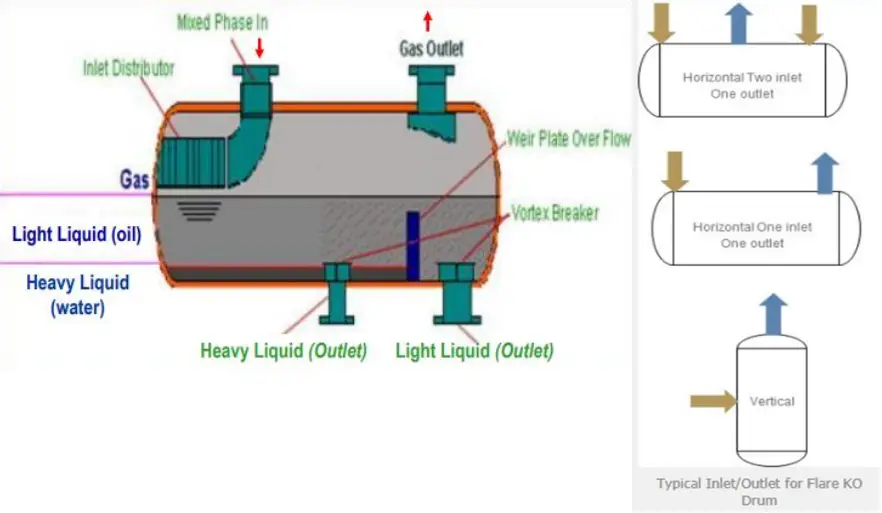
C. Flare Knock-Out Drum Sizing
The objectives of a knock-out drum are
- Limit liquid droplet size entrained with gas to the flare to avoid liquid carryover to flare tip, smoke, flaming rain, and other hazardous conditions.
- Provide adequate residence time for liquid.
Fig. 9 shows a typical known out drum (KOD). KOD is sized based on API 521.
- Separation of liquid droplet size of 300-600 microns considering the design case for the flare.
- 20-30 minutes of liquid hold-up time based on a relief case that results in maximum liquid.
- No internals to facilitate separation.
- Many orientations/options possible, horizontal KODs most preferred.
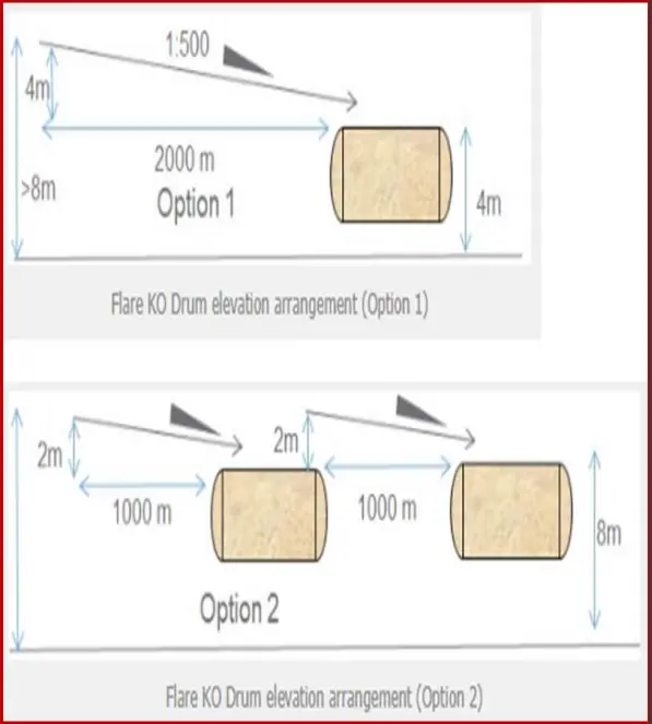
- Flare Knock-Out Drum Elevation
- KO drum elevation decides pipe rack elevation based on the 1:500 slope of the main flare header
- KO drum elevation determined by pump NPSH requirement
- To reduce pipe rack elevation options are
- Reduce KOD elevation (option 1 in Fig. 10)
- • Use a vertical can pump
- • Locate the pump within a pit
- • Locate the KO drum within a pit
- Use intermediate KO drums (option 2 in Fig. 10)
- Reduce KOD elevation (option 1 in Fig. 10)
Flare System KOD Design Considerations
- Flare KOD sizing depends on two aspects:
- Liquid Hold up requirement during a major liquid or two-phase release.
- A sufficient distance shall be available between the inlet & HHHLL. It is possible to have manually initiated depressurization even after HHHLLL. Any possible liquid shall be accommodated above HHHLL.
- Knockout drum sizing is basically a trial-and-error process.
- Distance between HLL and HHHLL shall be designed to accommodate the maximum liquid release scenario.
- Determination of the drum size for liquid entrainment separation is The first step.
- HHHLL is usually taken as the distance from the maximum liquid level.
- The vertical velocity of the Vapour and gas should be low enough to prevent large slugs of liquid from entering the flare.
- The thermal radiation fluxes and smoking potential are increased by the presence of small liquid droplets.
When do the Liquid particles separate?
- Sufficient residence time.
- When the gas velocity is sufficiently low to permit the liquid dropout to fall.
Long-term field experience has shown that the dropout velocity in the
drum may be based on the necessity to separate droplets from 300 μm to 600 μm in diameter.
D. Flare Stack Sizing
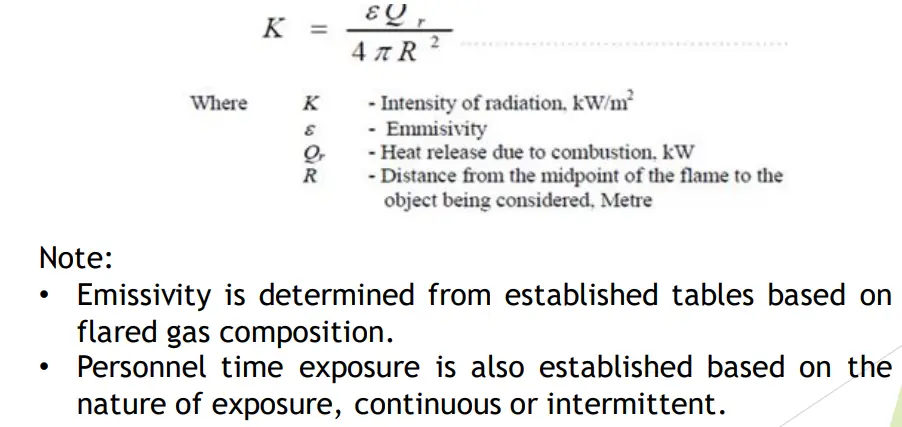
Flare Load, Radiation, and stack height:
Flare stack height depends on the flame radiation intensity, therefore you will need first to estimate the generated radiation in order to be able to identify the minimum acceptable stack height. Thermal radiation can be calculated by the following equation (Fig. 11):
Flame length is a determining factor for the intensity of radiation and its angle in relation to the stack. It can be calculated using the following equation (Fig. 12):
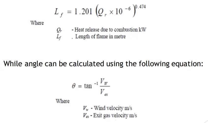
Using Flame length and flame angle, Radiation intensity can be determined and accordingly flare stack from charts.
E. Liquid Seal Drum
Liquid Seal Drum prevents the flashback from flare tip back to flare headers. It also helps to avoid air ingress into the flare system when the flare system is integrated with a flare recovery system or due to hot gas thermal contraction and/or condensation which can result in a substantial vacuum in the flare header. Fig. 13 shows a typical liquid seal drum.
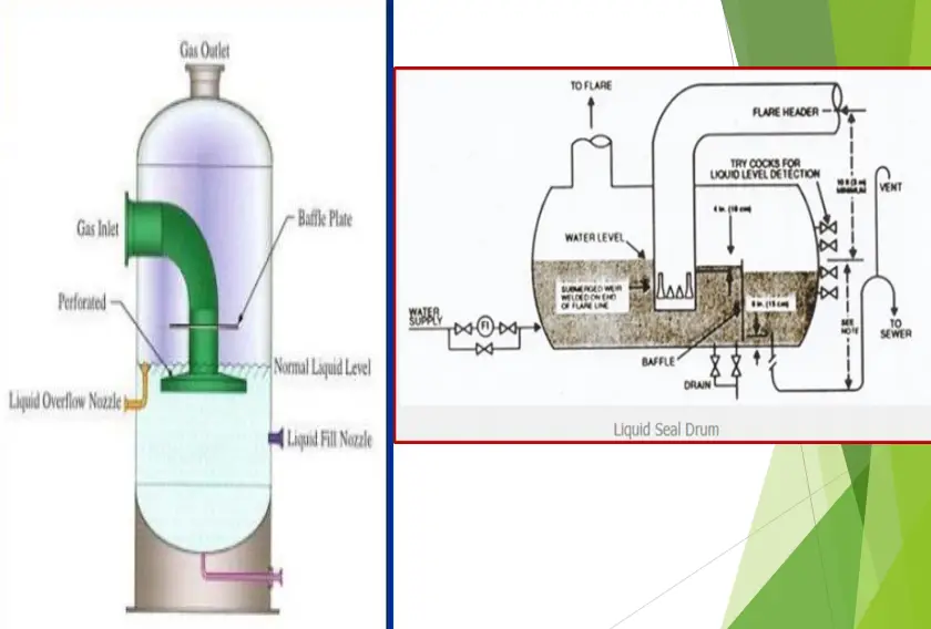
Note that the maximum vacuum protection achievable may be limited by piping and vessel elevations, In addition to maintaining the proper liquid level and restoring the level promptly after any hot relief and before the vacuum forms.
For extremely cold releases, the water as a liquid sealing fluid is not recommended. In such cases, water-glycol mixtures of sufficient concentration shall be used.
F. Flared Gas Measurement
As we get familiar with the impact of improper flaring on health and the environment, also it is highly required to measure the HC quantities sent to flare to decide on the plant performance, identify gaps and define the mitigating actions to eliminate or at least reduce flaring.
When trying to measure gas flaring, There are many challenges, including diameters of large pipes, high flow velocities over wide measuring ranges, gas composition changing, low pressure, dirt, wax, and condensate.
Important criteria to be considered to decide on the flow measurement instruments:
- Operating range, the meter should accommodate the anticipated range of flows.
- Accuracy will depend on the final use of the measurement data and applicable regulatory requirements.
- Installation requirements, the flow meter should be installed to be able to measure the total final gas flow to the flare and be located downstream of any liquids knock-out drum.
- Maintenance and calibration requirements.
- Composition monitoring as most types of flow meters is composition dependent. There are two primary options for composition monitoring:
- Sampling and subsequent laboratory analysis.
- Online Analyzers.
- Temperature and pressure corrections, the flow meter will need temperature and pressure compensation features to correct the measured flow to standard conditions (101.325 kPa and 15°C) or normal conditions (101.325 kPa and 0°C).
- Multi-phase capabilities, if the gas stream contains high concentrations of condensable hydrocarbons, the gas flow meter should be installed as close as possible to the knockout drum, and consideration should be given to insulating and heat tracing the line.
- Stainless Steel may be used for offshore platform’s corrosive saltwater on all exposed instrument materials, including sensors, process connections, and enclosures. Agency approvals for installation in hazardous locations, in environments with potential hazardous gases; enclosure-only ratings are inadequate (and risky).
- Monitoring records should be kept for at least 5 years. These records should be included the flow measurement data, hours the monitor during operation, and all servicing and calibration records.
- In flow verification, where a verifiable flaring rate is desired (provers), the systems should be designed or modified to accommodate secondary flow measurements to allow an independent check of the primary flow meter while in active service.
- Flow test methods may be considered for making spot checks or determinations of flows in the flare header.
- Stainless steel wetted parts and optional stainless steel process connections and enclosure housings.
- Non-clogging, non-fouling, no moving parts design for lowest maintenance.
- Must be in compliance with local environmental regulations. It should meet mandated performance and calibration procedures such as US EPA’s 10 CFR 40; 40 CFR 98; EU Directive 2007/589/EC; US MMR 30 CFR Part 250 and others
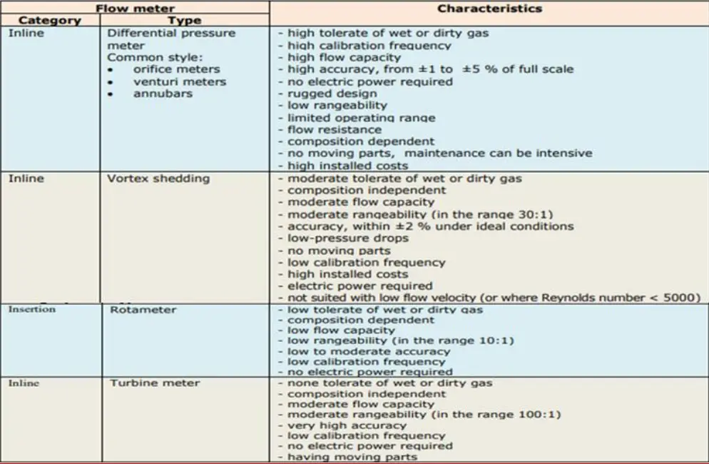
The main types of flow meter technologies for flare gas measurement in the industry are listed in Fig. 14 below:
Few more related articles for you…
Pre-Commissioning and Commissioning Checklist for Flare Package
Routing Of Flare And Relief Valve Piping: An article
Elevated Flare systems used in Process Industries
Flare systems: Stress Analysis Points
reports that you have made excellent, indeed things should be made accordingly,thanks
This is my great pleasure and kudos kept for my dear friend Anup and the moderators of this valuable platform who enable us to share information and knowledge.
It’s really nice, detailed and useful. Thanks for Blog
Really good document
Thanks for information
article is informative
Thanks a lot, I am happy to hear this
Any comments on optimal maximum pipe sizing or cut-off pressures for what goes to hi and low pressure headers or whether to consider a separate H2S rich flare?
Hi Ahmed Shafik,
This is Bala here from Singapore , I’m currently working as a Project engineer in PEC Singapore , i handle projects and we are the sub contractors for Exxon Mobil , will need your advise on the path forward in my career and the essential qualifications and certificates that will aid in my career progression in the oil and gas industry , thanks .