
Globe valves are linear motion closing-down valves used to start, stop or regulate the flow using a closure member referred to as a disc. The globe valve disk can completely close the flow path or can be removed entirely. The seat opening changes proportionately with the travel of the disc which is ideal for duties involving flow regulation. Globe valves are most suitable and widely used for throttling and controlling fluid flow and are generally employed in small-size piping.
A globe valve uses a linear motion for moving a disc (closure member) into or out of the seating surface. Globe Valves form a globular-shaped cavity around the port region and hence the name. The disc can be of various shapes and moves perpendicular to the globe valve seat. This disc movement helps in valve opening and closure. Globe valves in general are used for pipes of size 8 inches or less. In this article, we will explore the globe valve types, parts, working principles, functions, symbols, applications, advantages, and disadvantages.
In addition, depending on the design of the seat and disc, the seating load of globe valves can be positively controlled by a screwed stem. The sealing capacity of the globe valve is high. They can be used for on-off duty if the flow resistance from the tortuous flow passage of these valves is acceptable. Some globe valves are also specifically designed for low flow resistance for use in on-off duty. Because of the short travel distance of the disc between the open and closed positions, globe valves are ideal if the valve has to be opened and closed frequently. Thus, globe valves can be used for a wide range of duties.
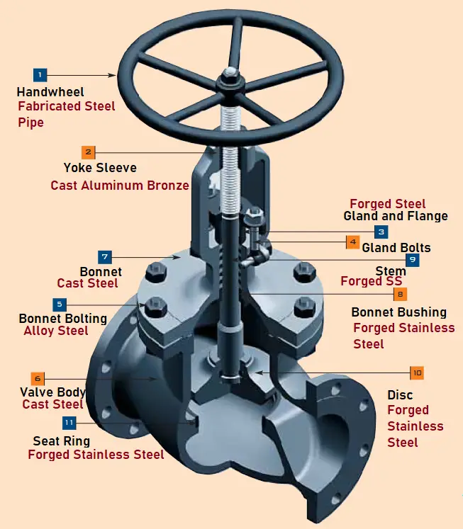
Globe Valve Parts
A typical globe valve constitutes of the following parts:
- Valve Body (6): Globular shape
- Bonnet (7)
- Disc or Plug (10)
- Stem (9)
- Yoke
- Gland bushing and flange (3)
- Seat ring (11)
- Yoke Sleeve (2)
- Gland Bolts and Nuts (4)
- Handwheel (1): Mechanical Actuator
- Back Seat
- Pressure Seal Gasket
- Packing
Types of Globe Valve
To meet the varied range of work duties at the lowest cost, numerous variations of globe valves are designed. The three most common types of globe valve configurations available for industrial use are
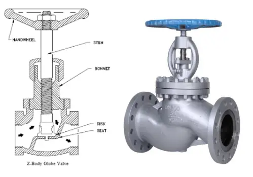
Tee Pattern (T-Type) Globe valves possess the lowest flow coefficient and a higher pressure drop. In severe throttling services, such globe valves can be used. If the pressure drop is not a concern and throttling is required, the Tee type globe valve will be a good choice.
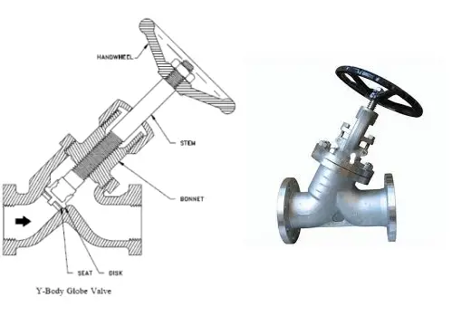
Wye Pattern Globe valves can be cracked open for long periods without severe erosion. They offer very low resistance to flow. For start-up operations, Y-type globe valves are extensively used.
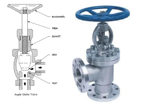
Angle Pattern Globe valves turn the fluid flow in a perpendicular direction without the use of an elbow. For pulsating flow services, angle-type globe valves are used because of their capability of handling the slugging effect.
Types of Globe Valves depending on Body Bonnet Connection
Based on body-bonnet connections the following types of globe valves are available:
- Screwed bonnet: Inexpensive, simple design.
- Bolted bonnet: most popular and widely used. Need a gasket for body and bonnet joint sealing.
- Welded bonnet: popular where no disassembly is required. lighter weight.
- Pressure-Seal bonnet: for high-pressure applications, this type of globe valve is used.
- Flanged bonnet: Can be designed for any size and operating pressure. However, with an increase in pressure, this type of globe valve becomes heavy and bulky.
- Union-ring bonnet: A separate screwed union ring is required to hold the bonnet to the valve body. This type of globe valve construction is usually limited to up to 3 inches in size.
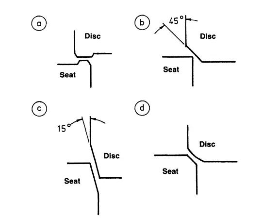
Globe Valve Seating
Globe Valves are provided with either metal seats or soft seat arrangements. To keep the seating stresses uniform, a number of variations of seating design are made. The following figure shows the most frequently employed seating configurations in globe valves.
The Function of a Globe Valve
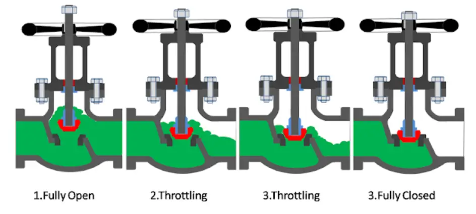
The main function of a globe valve is to start, stop, or regulate the flow. As the globe valve opens the disk moves upwards allowing the fluid to flow proportionally. In an open position, the valve stem rises and popped out at the top. Globe Valve is normally used in smaller sizes; mostly 12 inches or less in sizes. With an increase in the globe valve size, the power required to operate increases. In normal practice, a globe valve works as an on-off valve, but it can be used for throttling purposes as well.
Working Principle of Globe Valve
Refer to the cross-sectional image of the globe valve shown below. A globe valve is comprised of a movable disk and a stationary ring seat in a spherical body. The seat of a globe valve is in the middle of and parallel to the pipe, and the opening in the seat is closed off with the disk. As can be seen from the image, when the handwheel is rotated manually or by an actuator, the disc movement is controlled (lowered or raised) by means of the valve stem. When the globe valve disc seats over the seat ring, the flow is completely stopped.
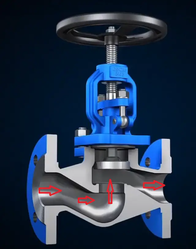
But when the disk is lifted the flow begins as the upward movement of the disc creates space for the fluid.
Globe Valve Disks
The position of the globe valve disk and seat can be described schematically as follows:
The Disc of a globe valve is made in three basic designs; Conventional Disc (or Ball Disc), Composition Disc, and Plug Type Disc.
Ball Disk:
In the conventional type of disc, the seat and disc construction is made of a ball-shaped metal disc. This possesses a short taper and it easily fits against a flat-surfaced seat in the body. For low-pressure services, this type of globe valve is quite popular and economical. Even though the ball disc is capable of throttling flow, but still primarily used to start and stop the flow.
Composition Disk:
A hard, nonmetallic insert ring is used on the disc of a composition disc design to create a tighter closure. For high-temperature and pressure applications, composition disks are used due to their sufficient resilience and erosion resistance. The composition disc globe valve is basically an improved version of the conventional disk-type globe valve. Composition discs can be replaced or repaired.
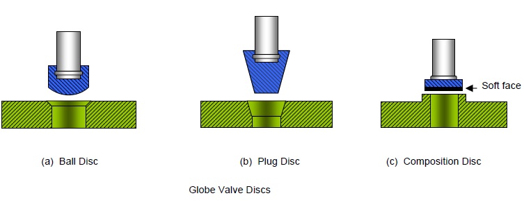
Plug Disk:
The plug disc is the best among all three globe valve disk designs and is suitable for throttling services. A long tapered metal plug is made into a plug disc that seats into a cone generating a wide seating surface.
Disc – Stem Configuration
The stem of a globe valve can rotate or not rotate while raising or lowering the disc depending on the design. Accordingly, various disc–stem configurations are available like
- Rotating Stem with Integral Disc
- Rotating Stem with Non-Integral Disc
- Non-Rotating Stem with Integral Disc
- Non-Rotating Stem with Non-Integral Disc
Because of the simplicity of design, most globe valves incorporate a rotating stem.
Globe Valve Flow Direction
For low-temperature applications, the flow direction in a globe valve is installed so that pressure acts under the disk. This design helps in easy operation, protects the packing, and eliminates a certain amount of erosive action to the seat and disk faces. Whereas, for high-temperature steam service, globe valves are positioned such that the pressure is above the disk. This will avoid the stem contraction upon cooling that may tend to lift the disk off the seat.
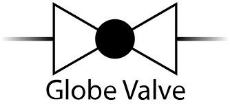
Globe Valve Symbol
The following globe valve symbol is quite popular in the piping industry. These are used in P&IDs to differentiate a glove valve from other valve types.
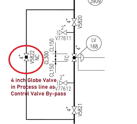
The following image shows the typical globe valve symbol used to denote a bypass valve in the control station.
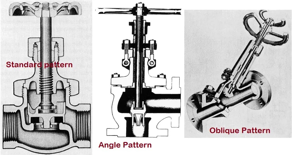
Globe Valve Patterns
Globe Valves are available in three body patterns.
- Standard pattern (T-Pattern or Z-Pattern)
- Angle Pattern
- Oblique Pattern (Wye Pattern or Y – Pattern)
Standard Pattern or T/Z– Pattern globe valves
This is the most common globe valve body pattern. The horizontal setting of the seat allows the stem and disk to move perpendicular to the direction of the fluid flow. This design provides the highest resistance to fluid flow among all of the available patterns. This standard pattern globe valve design has the lowest flow coefficient and the highest pressure drop. For severe throttling services and applications where pressure drop is not of much concern like in bypass lines around a control valve, this type of globe valve is commonly used.
Oblique Pattern or Y–Pattern globe valve
The oblique Pattern globe valve body design is suitable for applications requiring low-pressure drop. Their oblique pattern design reduces the resistance to the flow of the globe valve to a minimum. The seat and stem being angled at approximately 45 degrees, provides a straighter flow path at full opening and offer the least flow resistance.
Angle Pattern globe valve
Angle pattern globe valve body design is manufactured by modifying the basic standard pattern globe valve. The valve ends of this type of globe valve are perpendicular or at an angle of 900, and fluid flow occurs with a single 900 turn. As compared to the oblique pattern globe valves, they have a slightly lower coefficient of flow. For applications having pulsating flow because of their capability to handle the slugging effect, angle pattern globe valves are used.
When a globe valve is required near a pipe bend, the angle pattern globe valve body offers two advantages. First, the angle pattern body provides a greatly reduced flow resistance. Second, the angle pattern design saves the requirement of a pipe fitting and joint.
Advantages of Globe Valve
The main advantages of globe valves can be summarized as follows:
- Good sealing capability.
- Moderate to good throttling capability.
- Shorter stroke.
- Provide a wide range of capabilities as available in tee, Wye, and angle body styles.
- Machining and resurfacing the seats are easy.
- The globe valve can be used as a stop-check valve by modifying the design slightly.
Disadvantages of Glove Valve
The globe valve disadvantages can be listed as follows:
- Higher pressure drops due to many directional changes.
- Greater force or power requirement to seat the valve.
- Throttling flow under the seat and shutoff flow over the seat.
Applications of Globe Valve
Globe valves can be used in a wide range of services; both low-pressure and high-pressure fluid services. The typical applications of globe valves are:
- Cooling water systems requiring flow regulation.
- Fuel oil system requiring leak-tightness.
- Control valve bypass systems.
- High-point vents and low-point drains.
- Oil and Gas, Feedwater, chemical feed, Refinery, condenser air extraction, and extraction drain systems.
- Boiler vents and drains, Steam services, main steam vents and drains, and heater drains.
- Turbine seals and drains.
Globe Valve vs Gate Valve
The major differences between the globe valve and the gate valve are listed below:
| Globe Valve | Gate Valve |
| Globe Valve construction in complex, major internal components are inside the body cavity. | Gate Valve construction is simpler, with the majority of parts on top of the valve body. |
| Globe valves are characterized by High-Pressure Drop | The gate valve produces a relatively Low-Pressure Drop. |
| Globe Valve is unidirectional. | Gate Valve is a multidirectional valve. |
| Globe Valve is used for Flow Control. | Gate Valve is used only for Isolation. |
| The disk of the globe valve moves parallel to the flowing medium. | The gate valve disk moves perpendicular to the fluid flow. |
| Globe Valve offers more resistance to fluid flow. | Gate Valve offers little resistance to fluid flow. |
| Weight of same size and rating Globe Valve is more as compared to gate valve. | Gate valve weight is comparatively lesser. |
| Globe valve is Costlier due to the complex design | Gate valves are comparatively cheaper |
| Globe valves are typically not used for sizes greater than 12 inch | Gate Valves can be used for larger sizes as well. |
Globe Valve vs Ball Valve
The following table lists the major differences between a globe valve and a ball valve.
| Globe Valve | Ball Valve |
| Globe valves provide high-Pressure Drop | The pressure drop in ball valves is comparatively low. |
| Globe Valve uses a disk that operates against the flow. | A ball valve uses a ball that closes across the flow. |
| Globe Valve is a linear motion valve | A ball valve is a rotary motion valve. |
| A Globe valve provides better control than a ball valve | The ball valve provides better shut-off properties than the globe valve. |
| Globe Valve is cheaper than ball valves | The ball valve is more complex in design than the globe valve and hence costlier. |
| Slow Operation | Quick shut off, the possibility of water hammer. |
Globe Valve Standards
Globe valve manufacturers use the following codes and standards for designing globe valves for industrial applications:
API Standards for Globe Valves:
- API 623 – Steel Globe Valves-Flanged and Butt-welding Ends, Bolted Bonnets
- API 602–Steel Gate, Globe and Check Valves for Sizes DN 100 and Smaller for the Petroleum and Natural Gas Industries
- API 6D – Specification for Pipeline valves
- API 598 – Valve Inspection and Testing
- API 6FA – Fire Test for Valves
BS Standards for Globe Valves:
- BS 1873 – Steel globe valves and stop and check valves, flanged and butt welding ends
- BS 5152 – Cast Iron globe and globe stop and check valves
- BS 5352 – Cast and forged steel gate, globe, check and plug valves, screwed and socket welding ends
MSS Standards for Globe valves:
- MSS SP 80 – Bronze globe valves
- MSS SP-85 Cast iron globe and angle valves, flanged and threaded ends
- MSS SP 61 – Pressure testing of steel valves
- MSS SP 25 – Standard marking system for valves, fittings, flanges & unions
- MSS SP 45 – Bypass and drain connections
- MSS SP 42 – Class 150 (PN 20) Corrosion Resistant Gate, Globe, Angle, and Check Valves With Flanged and Butt Weld Ends
Nice , thanks for sharing .
for me as the one who is not an engineer and is looking for some basics in this industry just for my own knowledge as a sales person, your shared info are great. thank you. best of luck.
Good information about globe valves.
Classic Thanks indeed
the blog is informative and clearly explained the pros and cons of globe valve.
Your blog was very clear and very complete. Perfect !
Can we get a Y type Flanged Globe Valve (25mm, 600 Class SS 317 Flange to Flange distance 216 mm in the market? If yes, Pl. mention the name of Manufacturers/ Vendors
ANSI B16.10-dimensional standard is applicable to the above-mentioned Valve?
send me daily news latter.