
Isolation philosophy or positive isolation philosophy is a standard procedure that describes a method for isolating a section of a plant to permit safe operation & provide access for maintenance. The philosophy & criteria given in this article shall be incorporated into P&ID. It includes process equipment, piping, and utility equipment & piping as well as requirements of instrumentation isolation.
Positive Isolation Philosophy
The isolation philosophy has been classified into three different categories that include the isolation of
- Equipment
- Instruments
- Utilities
Equipment Isolation Method
The following tabulated format (Table-1) outlines the circumstances when single and when double block and bleed valves are to be used for equipment isolation. This phenomenon and the resultant isolation valving must be consulted throughout this philosophy, as this isolation has to be incorporated in a whole range of contexts from battery limit to equipment isolation.
| Configuration | Single | Double |
| Sour Service | ANSI 300# or less | ANSI 600# or above |
| Sweet Service | ANSI 600# or less | ANSI 900# or above |
| Non-Flammable Utility Service | All Classes | Not required |
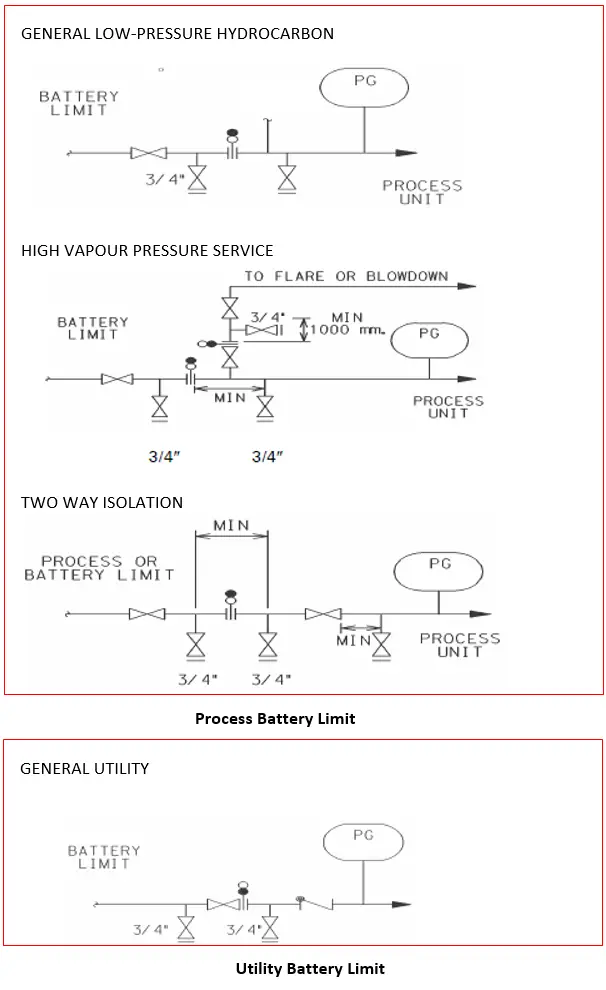
Battery Limit Isolation & TIE-IN Isolation
TIE-IN point to the existing and other process systems shall have ball valves. TIE-IN valves shall have spectacle blind, bypass ball valves (with spectacle blind). Also, spectacle Blinds shall be installed on all Battery Limit lines. At the blinding station, the block valve or valves shall be closed and the battery limit bleeder valve has been left open. Typical sketches for general hydrocarbon, high vapor pressure fluids, and two-way isolation are given in Fig. 1 below.
Equipment Isolation
Equipment can be isolated for several purposes like inspection, maintenance, etc. However, the main criterion for determining the level of isolation for equipment is whether personnel will enter into the equipment. Therefore the level of isolation for a large vessel will be greater than that for a small pump.
Equipment Isolation for Personnel Protection:
The following criteria should be incorporated into the design of isolation for any equipment whose internal isolation is required.
- All vessels, drums, and confined spaces shall be designed for positive isolation by blinding or by the removable spool.
- All inlet and outlet connections except those used for atmospheric ventilation will be subjected to positive isolation
- Vents shall be available on the equipment side of the isolation.
- The furnace/Waste heat recovery unit shall be designed for positive isolation so that humans can enter (for inspection and maintenance purposes) inside the equipment safely during the gas turbine running.
- Humans shall be able to enter inside the gas turbine exhaust duct (for inspection and maintenance purposes) safely during the Furnace/waste heat recovery unit running.
Equipment Isolation Configuration:
This section considers equipment that requires isolation for inspection and maintenance purposes but does not require internal access. The main examples of such equipment are
- Pumps: The below figures show the schematic for isolation configuration.
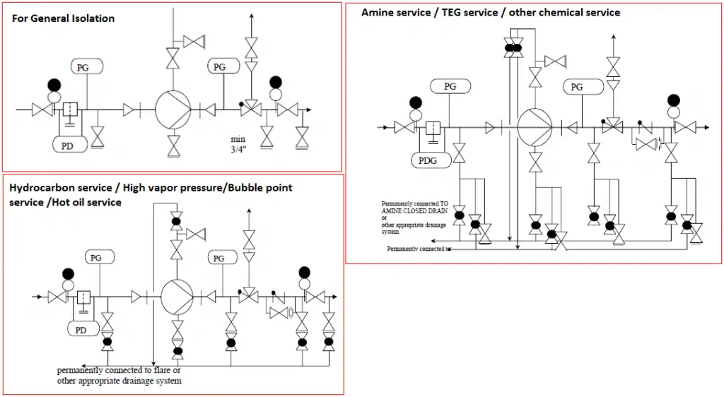
Notes:
- Double valves may be required depending on temperature, pressure, services
- Piping up to and including the suction isolation valve should be the same pipe rating as discharge where there are two pumps installed in parallel or where discharge can overpressure by backflow past the non-return valve.
Control Valve Isolation
Block and bypass valves shall be provided as standard for each control valve installation unless
- Identical pieces of equipment or process systems are installed in parallel enabling online maintenance of any one control valve without affecting the required capacity.
- Associated with intermittently operated or non-essential equipment.
- In applications where for safety reasons manual operation by means of the bypass is not desirable.
For applications where it is impractical to operate the process on a manual bypass valve, no bypass will be provided. The control valve isolation philosophy shall follow the guidelines for single and double isolation as per Table 1. Single isolation is acceptable for control valves providing that the normal operating pressure is within the specified class rating. For example, if a control valve in sour service is linking 600# to a 150# system, only single valve isolation is required downstream even though the isolation valve will be a 600# valve.
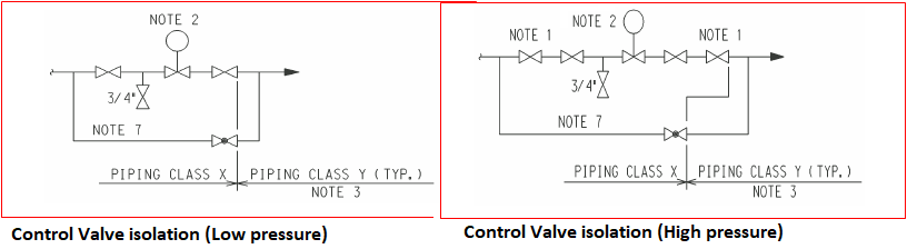
Notes:
- Double block & bleed valves as per Table 1
- Control valve failure action to be shown e.g. fails open (FO). Besides, any requirements of tight shut-off and TSO class are to be shown.
- It may not necessary to change the piping class across the control valve. If the downstream system has a higher rating the spec breaks need to be reviewed.
- Deleted
- Facility for flare vents may be required for large systems, etc.
- Deleted
- A gate valve shall be added in series along with the bypass globe valve on the product and sales gas lines.
Relief Valves Isolation
RV for series other than Thermal relief:
An isolation valve at the outlet with a lock-open facility shall be provided for all safety relief valves that do not discharge directly into the atmosphere.
An isolation valve at the inlet with a lock open facility shall be provided for all safety relief valves except for pumps with an installed standby where the relief valve is between the discharge block valve and the pump.
The isolation valves shall be key-locked using a proprietary valve-locking mechanism.
A key-interlock system must be specified (for the inlet and outlet isolation valves for both the service and spare RVs). In the case of 3-way valves, the valves at the upstream and downstream should be arranged such that they can be (are mechanically linked) switch simultaneously.
RV for Thermal relief:
RV relieving to flare/vent or process, a single block valve with an LO facility, and bleeder shall be specified only on the inlet line. For each valve, separate tailpipes should be provided.
RV relieving to the atmosphere a single block valve with an LO facility and bleeder shall be specified only on the inlet line. For each valve, separate tailpipes should be provided
Bypass Line:
A bypass line across the relief valves with a single isolation valve shall be specified only where there is a requirement to vent the gas in the system to flare/vent and no other connection to flare is provided.
Bleeder Valve/Weep Holes:
Bleeder valve requirements shall be noted on the RV arrangement, together with any requirement to vent at a safe location. Weep holes are required for valves routed to the atmosphere (to prevent rainwater from accumulating), with shielding or diversion for personnel protection as necessary.
RV Arrangement:
For spare relief valves, the arrangement for the isolation philosophy and connections shall be shown in the P&IDs if requires and shall be shown as per the figure below. Isolation valves should be interlocked.
Bonnet Vents:
A vent connection may be there from the bonnet for balanced bellows valves. These should be routed to a safe location and should not be provided with isolation valves. Fig. 4 shows the isolation philosophy for closed relief systems & open relief systems.
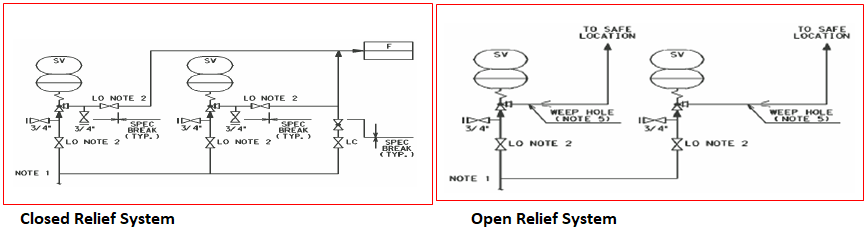
Notes:
- From the vessel or from the piping on the vessel without intervening valves.
- For spared SVs, isolation valves shall be interlocked such that one SV is always available. Double block and bleed valves should be used for high-pressure applications, refer to Table-1. The material of the proprietary key-interlock system shall be stainless steel. All keys shall be tagged. For each & every proprietary key-interlock system, one key shall remain and keep in the control room; a key cabinet (metal) with an identification label for each key shall be provided. The keyhole shall have a waterproof cover. In addition, a set of master keys shall be provided. This set of keys shall be valid for all proprietary key-interlock systems in this project.
- Deleted
- Deleted
- Special consideration is to be given to whether condensation could occur e.g. in steam service if valves leak badly, very hot water will come from the drain.
Instruments Isolation Method
Pressure Instruments:
Main Isolation valves shall be per Piping Specification. Screwed instrument connections may be used downstream of the main isolation valve only. Screwed connections shall not be used for instrument connections in hydrocarbon service. However, in applications where a flanged connection is not available, the following shall apply:
- For sour services and non-sour services in piping class ANSI 600 and above, pressure instruments may be connected by threaded connections, if no alternative exists, but only after double block and bleed isolation valves.
- In case of non-sour services of piping class ANSI 300 and below, pressure instruments may use threaded instrument connections after single block and bleed isolation valves.
- Back welding of flanges onto instrumentation is not acceptable.
Isolation of Utilities
Flare/Vent Isolation
The below figure (Fig. 5) depicts the standard isolation philosophy for the system connected to a flare or vent. F stands for Flare or vent.
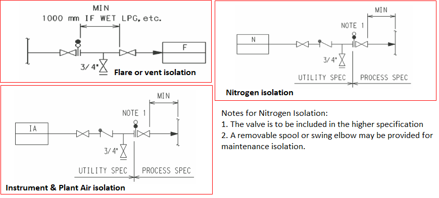
Instrument & Plant Air Isolation:
The standard isolation philosophy for instrument & plant air systems is provided in Fig. 5.
Nitrogen Isolation:
The standard isolation philosophy for the nitrogen system is also depicted in Fig. 5. Please refer to the notes mentioned in that Figure.
Potable Water:
Potable water shall be supplied to process users via a break tank to avoid contamination
You may also add few more lines to elaborate the following:
1) The objectives of isolation (isolating the equipment to enable work on it or positively preventing the flow/entry of a stream or breaking a flange to introduce a spade by stopping the flow from upstream and downstream side). The valves may leak or pass.
2) Isolation by Valves only or positive isolation (dropping the spool piece or introducing spade blind).
3) What risks are mitigated by double valve isolation and how? What is the reason to provide double valve isolation? Does it increase the reliability of isolation significantly? How much is enough?
4) Based on pipe rating, how the risk rises to the point that it starts requiring double valve isolation.
5) Spectacle blind should be on down stream of the isolation valve (to isolate the equipment) or upstream to isolate entering streams and achieve stream by stream isolation?
Can you please provide codes/standards referred for this and the section specific on the isolation philosophy