A Marine Loading Arm is used to load or unload the ship or vessel carrying Petroleum products, chemicals, etc. Marine loading arms are made up of several sections of pipe (quick-connect fittings), connected by swivel joints. The section on the shore side of the ‘apex’ of the loading arm is known as the inboard arm and the section on the tanker side of the ‘apex’ is known as the outboard section.
Marine loading arms are flexible enough to accommodate any movement of the vessel during loading/discharging. These hydraulically operated marine loading arms are fitted with emergency release couplings and emergency release systems and support faster and safety loading/unloading requirements.
A marine loading arm is an alternative to direct hose hook-ups. A loading arm must be drained before breaking off the connection. This is done in any one of the two ways mentioned below:
- For fuels like gas oil and diesel, high-pressure air can be used to blow out the oil traces.
- In the case of fuels such as kerosene or petrol, the lines can be stripped using pumps.
Loading arms have the capability to handle both liquids and gases, in a wide range of viscosities and temperatures. Cargoes from liquid sulfur to liquefied natural gas can be moved through marine loading arms.
Features of Marine Loading Arm
Marine loading arms (Fig. 1) must be specified/designed to allow for movement of the tanker during loading/unloading, due to tides/waves/wind and due to the tanker’s cargo increasing/decreasing. Each loading arm is designed with a certain operating ‘envelope’. If a connected loading arm is forced outside this envelope, it should be disconnected immediately (manually or, for some systems, automatically). The main factors that affect the required operating envelope are tanker DWT, tidal range, maximum wave height, the elevation of the jetty structure, and the size/number of loading arms at the berth.
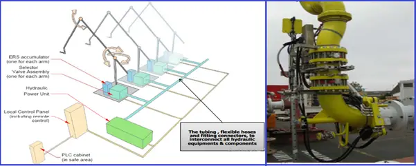
In general, marine loading arms are hydraulically powered. A hydraulic system, which often serves all the loading arms at a berth, is used to move the arms into position at the tanker’s rail, and to retract the arms back into the stowed position after use. It is common for loading arms to be one (or even two) sizes smaller than the associated pipelines.
When loading a small coastal tanker (up to say 5,000 DWT), it is normal to use only one marine loading arm (subject to loading arm diameter), whereas when unloading a large vessel (eg a crude oil VLCC in excess of 160,000 DWT), it is common to use up to four loading arms in parallel, in order to achieve the required flowrate.
There are a number of systems for connecting marine loading arms to tankers. The simplest connection is made using a flanged coupling. It is common practice for loading arms to be fitted with powered universal couplers. Marine Loading arms handling LPG (or any other pressurized/refrigerated material) should have a powered emergency release coupling (PERC), connected to the ESD system.
If the occupancy of a berth is very low by design, it may make sense economically to use hoses rather than loading arms. But there are factors that may outweigh the cost-benefit of hoses relative to loading arms, as follows:
- In order to handle hoses with a diameter of 4” and above, a crane is required
- In order to prevent snagging, hoses often need support that has to be adjusted during loading/unloading, for which a crane has required the environmental performance (in terms of emissions to air and to water) of a berth with hoses is generally not as good as that of a berth with loading arms
There are a number of standards relating to loading arm design and hose manufacture. Loading arms can be divided into two categories;
- those designed to handle liquefied gas (pressurized, refrigerated or semi-refrigerated) and
- those designed to handle Refinery products which are stored at ambient conditions.
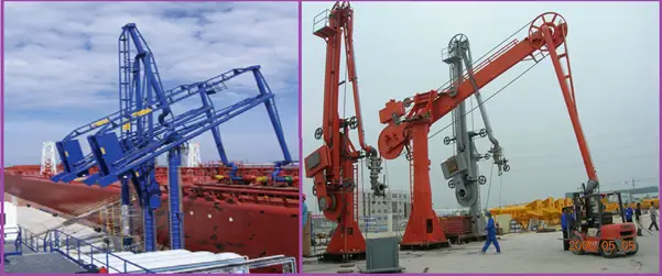
Marine Loading Arms for Refinery Products
For berth handling Refinery products that are stored at ambient conditions, it is common to have two pairs of loading arms to handle all non-refrigerated/pressurized products. Each pair of arms has a manifold such that one pair is dedicated to ‘white oils’ and one pair is dedicated to ‘black oils’. Product contamination is avoided by stripping and draining as part of the loading process, as follows:
- After pumping to the tanker is complete, the MOV upstream of the manifold is closed. These MOVs are generally the double seal design, to ensure product segregation.
- The liquid remaining in the manifold and the inboard section of the loading arm is then pumped out by the stripping pump. The stripping pump discharges either into the outboard section of the selected loading arm (i.e. onto the tanker) via a small ‘piggyback’ line, back into the supply pipeline upstream of the MOV, or to the on-shore slops system.
- Any un-pumpable material in the manifold is drained into an on-shore slops drum at the berth, leaving the manifold and loading arms empty.
For hydrocarbons stored at ambient conditions, the stripping pump should discharge into the outboard section of the loading arm because generally speaking the material has already been metered and therefore belongs to the customer.
Loading Arms for LPG at Ambient Temperature
For a berth handling LPG or any other material stored under pressure, it is common to have a vapour return system to take the vapours displaced from a tanker during loading. The flow of returned vapour should be metered. The vapour return can be a separate loading arm, but it is common for an LPG loading arm to be designed with a ‘piggy-back’ vapour return line i.e. two loading arms in one.
The returned vapour can be routed to the storage vessel from which product is exported. This enables high loading rates to be achieved but can be impractical/uneconomic over large distances, particularly if fans/blowers are required to boost the pressure in the vapour return pipeline. Returning vapours to the storage vessel give rise to the risk of a storage vessel being sent off-spec by contaminated returned vapours.
An alternative is to route the returned vapor to a local flare/vent system, with a pressure controller in the vapor return line to back-pressure the tanker.
When pumping LPG onto a tanker is complete, stripping of the loading arm(s) is usually achieved as follows:
- The loading arm/manifold is de-pressured into a dedicated closed sump, from which the drainings vaporize (with heating as required) into the vapor return system.
- The loading arm/manifold is purged with nitrogen to remove hydrocarbon vapors. Nitrogen purging is often carried out before connecting the loading arm, in order to remove air.
Loading Arms for Refrigerated LPG
Many of the considerations applicable to loading arms for products stored under pressure also apply to the design of loading arms for refrigerated (or semi-refrigerated) LPG, and for other products stored at below ambient temperature.
Additional design consideration for loading arms handling (semi) refrigerated products is the provision of a liquid return line to permit the chill down of the supply system prior to loading.
Design Code for Marine Loading Arm
Marine Loading Arms are Designed as per OCIMF (Oil Companies International Marine Forum) guidelines.
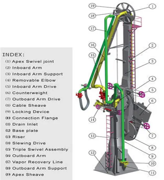
Main Components of a Marine Loading Arm
The main components of a typical marine loading arm is shown in Fig. 2 below.
- Riser Pipe
- Inboard Arm
- Outboard Arm
- Counter balance
- Connection Flange / QCDC
- Apex Swivel Joints
- Emergency Release Coupling
- Hydraulic System
Working of Marine Loading Arm
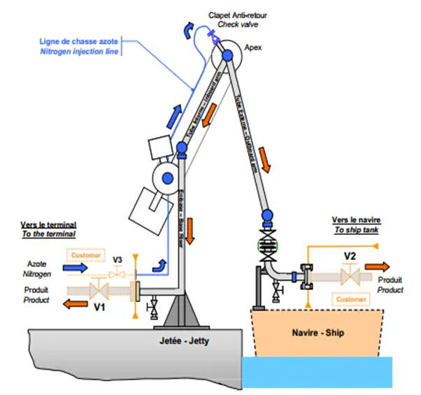
The working philosophy of a marine loading arm is shown in Fig. 3:
- Marine loading arm is designed based on its Operating envelop
- Marine Loading Arms are operated by using the hydraulic system.
- Heart of the marine loading arm is swivel Joint. Which plays an important role in operating the Marine loading arms.
Swivel Joints used in Marine Loading Arm
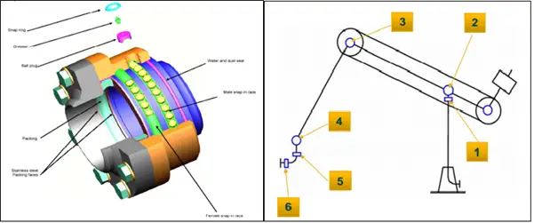
The main functions of the swivel joints (Fig. 4) in a marine loading arm are mentioned below
- Enabling the loading arm once connected, to follow the movements of the vessel within the working envelope.
- Allow the rotation between two items of a product line whilst ensuring no product leakage, even under external pressure.
- In a standard marine arm, there are six swivel joints with the direction of rotation in three planes giving the arm six degrees of freedom. This allows the arm to be maneuvered to and from the vessel and, once connected, allows the arm to follow all the motions of the vessel.
- Each swivel joint is made up of a male and female part joined by two or three bail bearing raceways allowing the free rotation of the joint. A compression type packing seal is used to seal the two parts of the swivel joint.
- Swivel Joints are available in various materials including carbon steel, LTCS, Hastelloy, Titanium, etc.
End Connection of Marine Loading Arm
- The End connection ((Fig. 5)) of the Marine Loading Arm is a standard ASME B16.5 flange.
- It is available in various sizes and ratings.
- It is also called a Quick connect / disconnect coupling (QCDC)
- End connections are of two types:
- Manually operated.
- Hydraulically Operated.
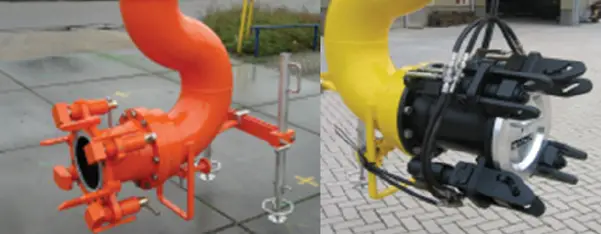
Emergency Release Coupling
Emergency Safety Systems are used to ensure the best possible safety in fluid loading/unloading operations with Marine Loading Arms.
The system allows a fully automatic and safe disconnection of the loading arm from the ship without product spillage when the arm exceeds the operating envelope’s limit line.
Hydraulic/Control System in Marine Loading Arm
Erection of Marine Loading Arms
Marine loading arms are normally shipped out fully pre-assembled with all their electronics and hydraulics systems already installed. When assembling the marine loading arms this saves considerable time and money providing economy to the end-user.
Materials of Marine Loading Arms
All Marine Loading arms can be made of various materials like
- Carbon Steel
- Stainless Steel 316L
- Stainless Steel 304L
- LTCS or Low-temperature Carbon steel

Great job!
May i know any risk when install a vent point at downstream of coris meter on Gasoil bunker outlet line?
Thanks for your brief explanation 🙏
My understanding, loading arm are balanced. The support leg is for facilitate connection/disconnection alignment with vessel’s manifold. Once connected the can lifted from drip tray and put back before disconnection. During cargo operation support legs should not take any load.
In term of operations is it true that MLA operation are controlled using device controller such as joystick?
Please explain..🙏🙏🙏
Hello excellent
Very good article. Very clear!
Hi, how much time does it usually take to connect and disconnect a loading arm to the ships manifold?
Nice to know you as professional engineer about loading arm, we are manufacturer of loading system, hopw we can get advices from you. Please send you contact email to me. Thanks.
Dear Anup Kumar Dey,
First of all, thank you so much for your article entitled “Introduction to Marine Loading Arm (With PDF)” which was really helpful.
I need allowable nozzle loads of loading arms. I want to know how much force and moment a loading arm can tolerate from piping connected to it (based on the nozzle diameter of the loading arm)
Can you help me with that?
I really appreciate any help you can provide.
Amir
Dear Sir,
Good Evening,
my name is hanumantha Rao, in the process of preparation of draft detailed project report, i wish to solicit some information regarding, marine unloading arms for the specific purpose of handling molten sufur from ship to shore.
Kind regards
I need a unloading arm to unload aviation fuel from a 3000 MT tanker to a fuel farm thro’ a 300 mm dia pipe line, in a International airport.
Can you work with us from the design to the supply , installation and commissioning process?
Which code to be refered for loading arm piping retiring thickness?
Very well systematically briefed. Well done.
Keep educating and continue the blog to explain other areas of piping / mechanical,….
All the bests
Great article Anup , thank you!