
1. What is Flange Leakage?
Flange leakage is a serious problem in the piping industry. It has a tremendous potential to cause severe hazards to operating plants. Hence, the possibility of leakage needs to be investigated during the design stage to reduce leakage possibility during operation.
- Basically, flange leakage is a function of the relative stiffnesses of the flange, gasket, and bolting.
- Flanges are designed to remain leak-free under hydrostatic test pressure when cold and under operating pressure when hot.
- The design of flanges (ASME B16.5) does not take into account the bending moment in the pipe. This generates a wire drawing effect on the mating surface of the flange. Hence, additional flexibility is to be provided when a flange joint is located near a point of high bending moment. So, Leakage checking is required.
Process Piping Flanges are designed in accordance with the ASME Boiler and Pressure Vessel Code, Section VIII, Division 1, Appendix 2, using allowable stress and temperature limits of ASME B31.3.
2. Reasons for Flange Leakage
Numerous possible reasons may cause a flange assembly to leak. Some of the common causes of flange leakage problems are:
- Excessive Piping System Loads:
- Forces and bending moments: can loosen bolts or distort flanges.
- Causes include insufficient flexibility, excessive mechanical force, and poor support placement.
- Incorrect Gasket Size or Material:
- Wrong size: noticeable during installation.
- Wrong material: This may cause issues like corrosion or blowouts later.
- Vibration Levels:
- Excessive vibration can loosen bolts, resulting in leaks.
- Thermal Shock:
- Rapid temperature changes can deform flanges and cause leaks, exacerbated by varying thermal expansions.
- Improper Gasket Installation:
- Off-center gasket: This leads to uneven compression and potential leaks.
- Fastener Issues:
- Too tight or not tight enough: uneven bolt stress due to improper tightening or loss of bolt tension over time.
- Overly tight fasteners: excessive pressure on gaskets or fatigue on equipment, especially in high-temperature conditions.
- Improper Flange Alignment:
- Misalignment causes uneven gasket compression and potential leaks.
- Flange Facing and Surface Finish:
- Deeper serrations: Can prevent proper gasket seating, leading to leakage.
- Damaged Flange Faces:
- Corrosion pitting: Creates leakage paths.
- Contaminants: Dirt, scale, scratches, protrusions, and weld spatter can lead to uneven gasket compression and leakage.
Most of the reasons mentioned above are construction-related, which can be eliminated by following proper best practices during construction activity. However, the major design cause that could result in flange leakage is excessive forces and moments that can be controlled during the design phase. The following section provides flange analysis methodologies to check the suitability of flanges against high forces, which may cause excessive stresses.
3. Flange Leakage Analysis Criteria
The criteria regarding when flange leakage checking is required should be mentioned in the ITB (Invitation To Bid) documents or project specs. But as a general practice, the following can be used:
- Flanges with a rating of 600 or more
- Flanges with a rating of 300 and size greater than 16 inch
- Pipe flanges carrying category M fluid service
- Pipe flanges carrying Hydrogen or other flammable fluid
- PSV lines with NPS 4 inch or more
- All Flanges in Jacketed Piping
- Flanges where stress engineer finds a very high bending moment
This list is not exhaustive. Always refer to your stress or project guidelines for more details about flange leakage criteria.
4. Flange Analysis Methodology
Four widely used flange analysis methods are practiced in the prevalent process or power piping industry. These are
- Pressure Equivalent method based on ASME B16.5 pressure-temperature rating table and
- ASME BPVC Sec VIII Div 1 Appendix 2 method.
- NC 3658.3 method
- Flange Leakage Analysis Using EN-1591
- Other Flange Analysis Methods
4.1 Flange Leakage Checking by Pressure Equivalent Method
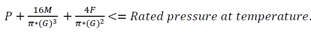
In this method, the generated axial force (F) and bending moment (M) on the piping/pipeline flange are converted into equivalent pressure (Pe) using the following equations.
- Equivalent Pressure for Axial force, Pe1=4F/ΠG2
- Equivalent Pressure for bending moment, Pe2=16M/ΠG3
- Here G=diameter at the location of gasket load reaction =(Gasket OD+ID)/2 when bo<=6 mm =(Gasket OD-2b) when bo>6 mm. Here bo=basic gasket seating width as given in table 2-5.2 of ASME sec VIII
These two equivalent pressures are then added with pipe or pipeline system design pressure (Pd) to find the total pressure (Pt=Pd+Pe1+Pe2) and checked against the rated pressure at the temperature for the flange. The rated pressure is found in the ASME B16.5 (ASME B16.47 for flanges with size 26 inches and more) pressure-temperature rating table associated with flange material. If Pt is less than the allowed pressure on the rating table corresponding to the associated temperature, then the flange will not leak.
Hence the requirement for this method is Design Pressure (P):
4.1.1 Drawbacks of the Pressure Equivalent Method
The major drawbacks of the pressure equivalent method are:
- The flange leakage analysis by the pressure equivalent method is too conservative, resulting in significant changes to the piping layout and support and hence impacting cost and schedule. In some cases, the allowable bending moment may be as low as 5% of the pipe yield.
- It does not address the issue of bolting and gaskets, two important factors for controlling leakage.
- The pressure equivalent method of flange leakage checking does not compute stresses in gaskets, bolts, or flanges. On the flip side, its overly conservative approach keeps the stresses on these components, subject to the proper selection of material, installation, and fabrication, to low magnitudes.
The steps for the pressure equivalent method in Caesar II software are explained here…
4.2 Flange Leakage Checking by ASME BPVC Sec VIII Div 1 Appendix 2 Method
This method is the widest one used in the industry where rules of ASME SEC III NC3658.3 are not applicable (B16.47 Flanges). In this method, flange stresses (longitudinal hub stress, radial flange stress, and tangential flange stress) are calculated based on ASME code-provided equations and formulas. These calculated stresses are then compared with allowable stresses as given in ASME BPVC Code Sec VIII Div 1 Appendix 2, Clause 2-8.
The mathematical basis for the computation of the stresses is in the work of Rossheim and Waters, where the governing equations for a circular plate (for the flange) and for a cylindrical shell (hub/pipe) under the action of internal pressure were supplemented with deformation compatibility at the interface between the hub and the ring and hub and pipe.
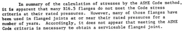
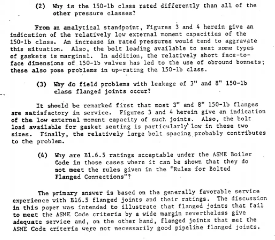
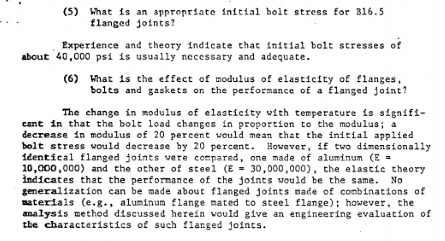
It’s important to note that many B16.5 flanges fail to meet the ASME code requirements, especially when a recommended magnitude of installation bolt stress of 40 Ksi is used. As Rodabaugh explains in Background of ANSI B16.5 Pressure Temperature Ratings (API 54-72).
Also, in the same report, Rodabaugh answers certain critical questions –
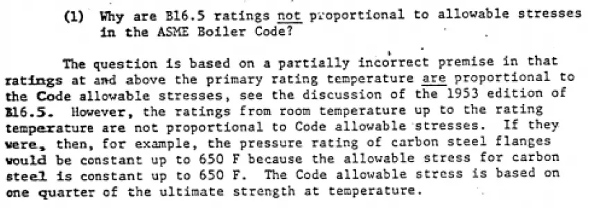
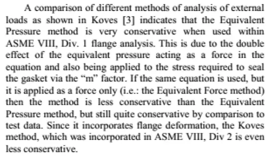
If ASME SEC VIII Div 1 Appendix 2 is implemented, then there is no way other than to convert the applied external bending moment and axial force as an “equivalent pressure,” which is what CAESAR II does. This approach can be seen as overly conservative, and the following is taken from ASME PVP-97814.
If however this method has to be implemented ( as many clients demand in their engineering standards), a few relaxations can be done, like checking if the computed bolt stress in seating and operating conditions are within 65% of SMYS for SS and 85% of SMYS for CS; alternately, if using the approach stated in ASM PCC-1 Appendix O, it can be shown that the combination of internal pressure and external bending moment and axial force is within the limits of equation (8), the joint can be qualified as acceptable.
For calculating flange stresses, one needs to calculate the flange moment, which is dependent on bolt load. Bolt load has to be calculated for two design conditions: operating & gasket seating and the most severe will govern. For more details on the equations and calculation methodology, the above-mentioned code can be referred to.
Some more ready references for you:
Flange Selection Guidelines
Pressure Equivalent Method in Caesar II
Flange leakage calculation ASME Section VIII in Caesar II
Flange leakage calculation NC 3658.3 method in Caesar II
Procedure for Flange Bolt Tightening of Various Sizes of Flanges
4.3 Flange Leakage checking by NC 3658.3 Method
In this method, the flanges are evaluated using the ASME BPVC Section III Subsection NC-3658.3 method. The calculated flange moments are compared to some limited values as calculated from the code equations.
The theoretical basis for this method lies in the computation of bolt stress due to pressure and applied bending moment and ensuring that the flange is not overstressed. This brings out the inherent weakness of not addressing the issue of gaskets. This method also presupposes an application of 40 Ksi of tightening stress for B16.5 flanges.
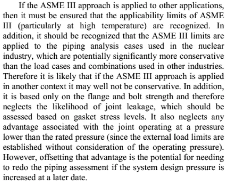
This method is recommended for high-strength bolts (allowable stress >20 Ksi) and for B16.5 Flanges. However, as the basis of computation is a control on bolt stress under pressure and bending moment and ensuring that flanges are not overstressed, its use in B16.47 Flanges can logically be extended, ensuring that the bolts and flanges are not overstressed. Moreover, as long as the applied bolt stress meets the requirements of ASME PCC-1 Appendix O, it ensures that the issue of adequate gasket compression is also taken care of, of course, subject to the condition that the flange is within the size limitation of ASME PCC-1 (48 inches). Some words of caution on the use of NC3658.3 from ASME PVP2013-97814 are shown below
For more details on the Caesar II application of the NC method, click here.
4.4 Flange Leakage Analysis Using EN-1591
The EN 1591-1 calculation code offers a comprehensive method for analyzing flange leakage by considering the behavior of all components involved—flanges, bolts, and gaskets. Unlike simpler methods, EN 1591-1 accounts for factors such as gasket thickness reduction due to flange stress and changes in gasket elasticity with temperature variations. This advanced approach provides not only an allowable stress check on the components but also an indication of the expected leak tightness of the flange assembly. It is applicable to both regular piping flanges and custom-designed body flanges for equipment. The code incorporates gasket characteristics based on EN 13555, including maximum allowable surface pressures, modulus of elasticity, and minimum seating pressure for various tightness classes. Additionally, it factors in the coefficient of thermal expansion of flange and bolt materials
4.5 Some Other Flange Leakage Methods
4.5.1 Blick’s method
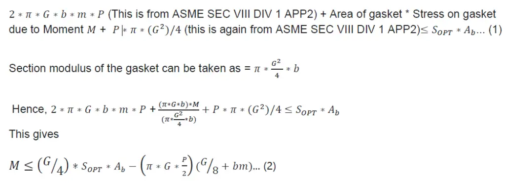
In essence, this method stands for -Internal Pressure force on gasket + residual compressive force on gasket + force on gasket due to applied bending moment should be equal to operating stress on each bolt times total bolt area.
4.5.1.1 Derivation of Blick’s formula-
4.5.1.2 Drawbacks of this method-
- Relative deformation and stiffness of bolts, gaskets, and flanges are not considered.
- Flange stress is not discussed.
- How to calculate operating stress on bolts is not discussed.
- The basis for the m factor in ASME B&PV code Sec VIII Div 1 Appendix 2 is not known, and hence their accuracy is a question by itself.
- An improvement of this method can be to compute 𝑆𝑂𝑃𝑇 using ORNL2913.3 [8] and ASME PCC-1 Appendix O
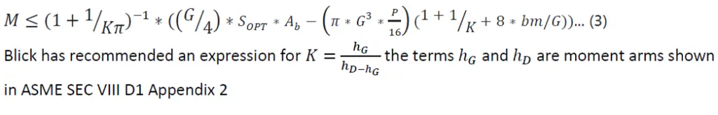
4.5.1.3 Modified Blick’s Formula
Blick proposed modification to the above formula (eon) and the modified version of Blick’s method is
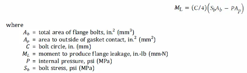
4.5.2 ASME B31.8 Method of Flange Leakage Analysis
The essence of this method is that when the force on the BJF due to applied internal pressure and applied bending moment (converted to a force) reaches a critical value, residual stress on the gasket equals zero.
As per ASME B31.8, Table E1, Note 14, the moment to produce leakage of a flanged joint with a gasket having no self-sealing characteristics can be estimated by the following equation:
4.5.2.1 Drawbacks of the method-
- The effect of applied loading on Flange and hub stress is not discussed
- Gasket stress is not discussed.
- Bolt preload and the load reduction in the bolt are not discussed.
- Relative deformation and stiffness of bolts, flanges, and gaskets are not discussed.
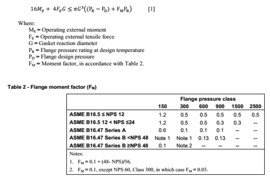
4.5.3 New method developed by Integrity Solutions (Warren Brown), Australia
The following is taken from the paper ASMEPVP2013-97814, citing the relevant equation for the new method:
5. Recommended Good Practices to Avoid Flange Leakage
Here are some of the recommended practices that can be followed to avoid flange leakage issues:
- The acceptable limit of bolt stress during tightening- 65% of SMYS for SS and 85% of SMYS for CS.
- Use of proper lubricant- Molybdenum disulphide.
- Bolt load scatter should be considered with a typical value of 5-10% of the target value.
- Although tensioning, in general, is a better approach than torquing, but for l/d ratio or length-to-diameter ratio of bolts to <=3, tensioning is normally not recommended.
- Two factors govern the loss when using bolt tensioning: Tool load loss factor (TLLF) and Flange load loss factor (FLLF); the latter being the additional case when 100% tensioning is not possible/applied. This aspect has to be considered when applying the right magnitude of bolt stress. The challenge will be to ensure that even with consideration of TLLF and FLLF, the bolt stress should not go beyond 65% of SMYS for SS and 85% of SMYS for CS.
- Ambiguity appears between sections 5.3.4 and 5.4.2 of B16.5 on the selection of a proper gasket for low-strength bolts. Since the use of low-strength bolting does not allow high gasket stress levels to be achieved during assembly, this issue should be considered in selecting a proper gasket for use with low-strength bolts. The same recommendation should be followed in B16.47 (for this document, the ambiguity on the same issue is exhibited in the paragraphs with the same no’s as in B16.5). For B16.5 the referenced edition is 2013 and for B16.47 the referenced edition is 2010.
- To avoid problems with sealing, it is recommended that the purchased flanges be having a 3.2*10-3 m concentric groove surface finish with a nominal 5 mm tool nose radius and 0.45 mm pitch. This is in relation to avoiding problems with leakage with spiral finish and 250*10-3 mm surface finish (section 6.4.5.3 of B16.5). The same recommendation should be followed in B16.47 (relevant paragraph 6.1.4.2 in B16.47) For B16.5 the referenced edition is 2013 and for B16.47 the referenced edition is 2010.
- For accepting flanges with imperfections, it is recommended that the limits outlined in ASME PCC-1-2013 Appendix D be used in lieu of Section 6.4.6 of B16.5; the same recommendation should be followed in B16.47 (the relevant paragraph is 6.1.5). For B16.5 the referenced edition is 2013 and for B16.47 the referenced edition is 2010.
- It is recommended that the minimum hub height be limited to greater than 75% of the full hub height. The same recommendation should be followed for B16.47.
- When using B16.20 gaskets with B16.47 Series A Class 150 flanges, custom dimensions should be specified ( the ideal gasket sealing element OD is between 6 mm and 12 mm smaller than the flange seating surface OD) such that the OD of the sealing surface is closer to the raised face O. The dimensions as they are in B16.20 can result in joint leakages.
- For selecting minimum pipe wall thickness for the use of spiral wound gaskets with inner rings and B16.5 flanges, the minimum specified dimensions in B16.20 (Table 15 in the 2012 edition of B16.20) should be followed. Recommendations in Tables 16 and 17 of the 2012 edition (maximum bore of B16.5 Flanges for use with spiral wound gaskets and maximum bore of B16.47 Series A flanges for use with spiral wound gaskets) should also be followed.
References:
- ASME B16.5
- ASME BPVC SEC VIII
- https://docs.hexagonppm.com/reader/O04dxcwMfibZIK1cyksZvQ/libWcNN9xB96GAfpXDAXlg
- ASME PCC-1-2013 Guidelines for Pressure boundary bolted flanged joint assembly.
- Demonstrating leak tight joints during Piping Design -ASME PVP2011-57923 by David Meir, ASME PVP conference , Baltimore 2011.
- Dissecting the dinosaur: problems with B16.5 and B16.47 Flange standards ASME PVP2013-97813 by Warren Brown, ASME PVP conference, Paris 2013
- Improved analysis of external loads on Flanged joints, ASME PVP2013-97814 by Warren Brown, ASME PVP conference, Paris 2013.
- WRC Bulletin 473-External bending moments on bolted flanged joints
- Behaviour of bolt force changes of flanged connections under thermal loading ASME PVP2013-97730 by M.Hiratsuka, T.Kobayasi
- FLANGE: A computer program for the analysis of Flanged joints with ring-type gaskets- by E.C.Rodabaugh and H.C.Moore
- Evaluation of the bolts and flanges of ANSI B16.5 Flanged joints-ORNL 2913.3, E.C.Rodabaugh and E.C.Moore
- Working bolts near to yield -Theory, experience and recommended practise -Robert Noble, PVP2013-97956, ASME PVP conference, Paris 2013.
Some parts of this article are taken from Mr. Anindya Bhattacharya’s studies on Bolted Flange Joints
Hey i must say that you have done a super work by sharing method for checking the flange leakage and if it is stainless steel flange bolts then after fixing forgot for years.
dowel pins |clevis pins | DIN 7
Thank you very much…
Very good article. Congratulations.
Good , usefull basic one shd remember
Hi Anup, this website is pretty helpful for the stress engineer, i give you the thanks for sharing your Knowledge. I have a question, according to the Section VIII Div 1 Sec. 2. I have analyzed several flange studies and almost always I find out that the Bolting Stress is “Overstress” for flanges of 150#, specially those ones between 6″ & 20″.I have read on the COADE forums that this is a mistake on the Standard, because several flanges have been done and they didn’t have problems during it’s operational cycle. So I want to asked to you if you found out this too. And why this happens. Thanks.
JAB
Yes I also find the same results..In 90% of situations 150 rating flanges are failing in Caesar II…I asked Coade about the same..but they could not provide any satisfactory reply…
Hi,
Just to add to your discussion, the standard flanges of ASME B16.5 have been taken from some old standards (i dont remember the exact one) which was based on practical testing rather than analysis.
The analysis in ASME Sec VIII Div 1 was developed much later. Hence most of the standard flanges as per B16.5 do not pass in the analysis as per Div 1 App 2 but are still in use because they have been proved effective through practical use over the years.
Dear,
I hope you are doing fine buddy, I would like to congratulate that way you are continuing sharing knowledge here.
As a general remark, I would like to add to this discussion that usually we have 150# flanges in lines where pressures are low. However I have encountered the same problem.
As a practice I’ve started to shift the flange connection i.e., break-up flanges/ valve assembly etc near to support location (if possible) in coordination with layout group. This hugely decreases the bending stresses at connections & design becomes safe.
However, another solution is to switch the class from 150# to 300# at those points where Peq failure is more that 200-250%, as a general note, most PMS allows one rating higher flanges available.
Do I need to follow the client comment in running the flange leakage for 150# lines with temp. Of 50 deg C with Fuel oil product that does not fall on flammable fluid?
Client requirements are the final requirements. So you have to perform leakage checking
Could you describe wire drawing effect specifically? I can understand overall theory, however i can’t understand what is wire drawing effect.
Hi all,
Thank you for this nice article.
I would like to add that under ASME Sec VIII Div 1 App2 method, in addition to calculation of induced stresses, flange rigidity check should also be done and checked if Flange rigidity <=1 for both operating & seating condition so that leak tightness is ensured.
Even after all calculations are performed, the actual bolt tightening done on the flange also affects the joint integrity and leak tightness. For this ASME PCC-1 App O gives guidelines using joint component approach.
Though it is not mandatory, it can also serve for ensuring leak tightness of the joint.
Thanks.
interesting article!
thanks a lot nice article
Just wanted to share that the European standard, EN-1591, which is a very detailed flange leakage assessment is now supported in CAESAR II 2019 (V 11) as well. It is geared to use on very specific and the most critical of flange assemblies.
Hi , can you share for me if you have any guideline for the European standard, EN-1591 methods ?
Could you explain the PCC-1 calculation
Hello, talking about all the methods for checking flange leakage, have you ever analyzed this paper: Robert G. Blick: “Bending Moments and Leakage at Flanged Joints” (published in 1950 as “A Gulf Company Publishing Publication, Sun Valley, California – Petroleum Refiner” in 3 parts: Vol.29 – No.2, February (Part I); No.5, May (Part II); No.6, June (Part III))
Max. allowable bending moment: M = Min (M1, M2)
M1 = Criterion for sufficient gasket pressure = …
M2 = Criterion for excessive gasket pressure = …
I’ve tried to apply it, but the results seem very instable. I’ve never seen this applied practically, but one of my clients had this as a possible method.
Thanks for your time.
Hi Anup,
Just want to know one thing how to calculate the moment & forces.
There is an app that taken into account of external force and moment together with ASME section VIII method,
https://apps.apple.com/us/app/flange-leakage/id1573350477?ign-mpt=uo%3D2
Sir, i have read this article.it’s very useful to me. But I have doubt regarding wire drawing effect in flanges.. what is meaning of wire drawing effect as you have mentioned in starting that “The design of flanges (ASME B16.5) does not take into account the bending moment in the pipe. This generates a *wire drawing effect* on the mating surface of the flange.”
Good for sharing.