
The full form of P&ID is Process and Instrumentation Diagram. This is an engineering document developed by process engineers that shows the piping and other related items for process flow. A P&ID provides a detailed graphical representation of the actual process system that includes the piping, equipment, valves, instrumentation, and other process components in the system. All components are represented using various P&ID symbols.
The graphical representation in a P&ID drawing establishes the functional relationship of piping, instrumentation, and mechanical equipment. P&IDs are one of the most important documents for any project and are crucial in all stages of process system development and operation. This is the most extensively used engineering document and is used by all engineering disciplines like Process, piping, mechanical, civil, HVAC, electrical, and instrumentation.
What is P&ID used for?
A P&ID (Also known as PEFS, Process Engineering Flow Scheme) is a fundamental engineering document that serves various purposes as mentioned below.
- P&IDs Provide key piping and instrumentation items along with their proper arrangement.
- It serves as a basic document for operation, control, and shutdown schemes.
- The piping and Instrumentation diagram provides a basis for maintenance and modification works.
- It gives the regulatory and plant safety requirement.
- A P&ID drawing serves as a guide for start-up and operational data.
- P&IDs are used to develop guidelines and standards for facility operation
- It is the basic training document to explain the process details to operation guys, field engineers, and maintenance professionals. The P&ID drawings help them to track the interconnection between the piping and instrumentation and equipment.
- A P&ID provides the design and construction sequence for the plants for systematic planning of activities.
- They serve as a basis for studying different mechanical and chemical steps to find the root cause if something goes wrong.
- It also provides basic information for initial project cost estimation.
- An important document for HAZOP, Model review, Process Safety Management, etc is the process and instrumentation diagram.
- Finally, the P&ID drawing provides a common language for discussing plant operations.
Limitations of P&ID
P&IDs being graphical schematic process representations have some limitations like
- They are not on a scale, similar to real models.
- They are not standardized documents so vary from company to company.
What should a P&ID include?
There is no exact code or standard that dictates what exactly should be included in the P&ID drawing document. That is the reason P&IDs from different organizations vary slightly. Broadly, all P&IDs normally include the following:
- All Mechanical equipment with equipment numbers (Tags) and names.
- All valves with proper identification.
- Instrumentation details with designations.
- piping with line numbers, sizes, material specs, and other details.
- Fluid Flow directions.
- Miscellaneous items like drains, vents, special fittings, reducers, sampling lines, expansion joints, flexible hose connections, increases, and swaggers.
- Piping and equipment interfaces with scope demarcation, and class changes.
- Permanent start-up and flush lines.
- References for Interconnections.
- Interlocks, Control inputs, and outputs.
- Annunciation inputs
- A physical sequence of the piping items and equipment.
- Equipment rating or capacity; sometimes short design and dimensional details.
- Interfaces with vendors and contractors with scope.
- Computer control system input.
- Seismic category
- Quality level
- Details like equipment operating, standby, normally no flow, etc are included in some P&IDs.
- Notes related to two-phase flow, special pipe length requirements, etc.
- Piping slope requirements, Piping Insulation requirements.
Details excluded in a P&ID
The in-depth details are not included in the P&IDs. Various supporting documents are prepared for the detailed design and description of those items. Normally the following details are not included in a P&ID:
- Process Flow Diagram
- Pipe Route and length
- Elbow, tees, and similar standard fitting details.
- Pipe Support and Structural Details
- Pressure temperature and flow data.
- Manual switches and indicating lights
- Extensive explanatory notes
- Control relays
- Instrument root valves
- Primary instrument valves and tubing
- Equipment rating or capacities
- Equipment locations
Supporting Documents of P&ID
As the Piping and Instrumentation Diagram is not a detailed document, various supporting documents are prepared to complete the overall details of the P&ID. Few of those documents are:
- PFD or Process Flow Diagram from which P&ID is generated.
- PMS or Piping Material Specification which provides material details of piping and related items.
- Equipment and Instrument Item datasheets specifying the required details about Equipment or instrument items.
P&ID Symbols
Process engineers use various P&ID symbols while constructing P&ID drawings. All those P&ID symbols are normally described at the start of the P&ID set. For the same design consultant, those symbols are normally constant. One should familiarize himself by studying those P&ID symbols to accurately read the P&ID drawings.
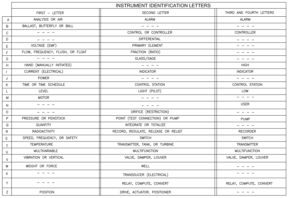
Instrumentation symbols in a P&ID are standardized as per ANSI/ISA’s S5.1 standard. This standard ensures a consistent, system-independent means of communicating instrumentation, control, and automation intent by providing standardized Instrumentation Symbols and Identification so everyone understands.
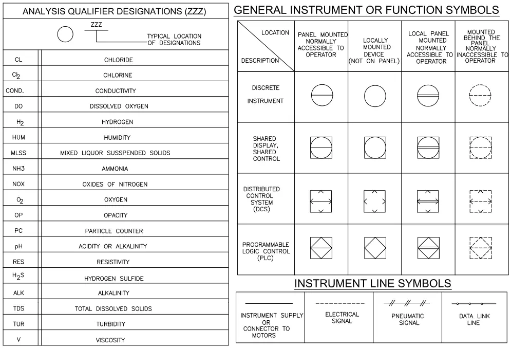
Four graphical elements are defined in ISA S5.1 for instrumentation. Those are discrete instruments, shared control/display, computer function, and programmable logic controller. The standard also groups them into three location categories as the primary location, auxiliary location, and field-mounted location category. Click here to check all the P&ID symbols that ANSI/ISA’s S5.1 standard provides.
BS 5070 and ISO 10628 also provide a few guidelines and best practices for P&ID symbols. The following images (Fig.1 to Fig. 7) provide an example of the P&ID symbols that are normally used in a typical P&ID.
Instrument Symbols in P&ID
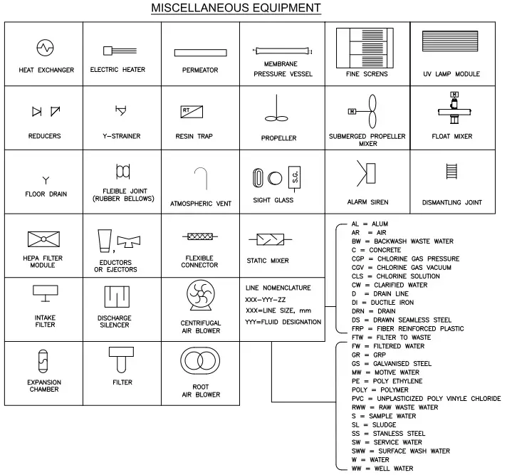
P&ID Equipment Symbols
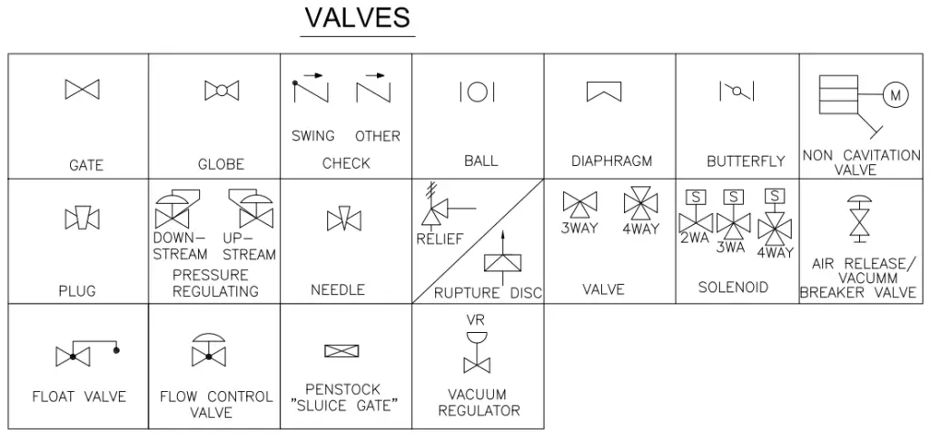
Valve Symbols in the Piping and Instrumentation Diagram
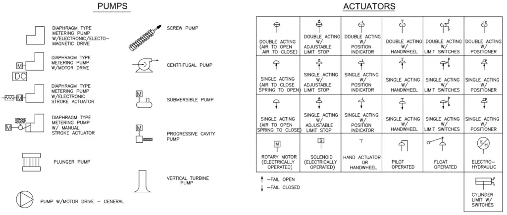
P&ID Symbols for Pumps and Actuators
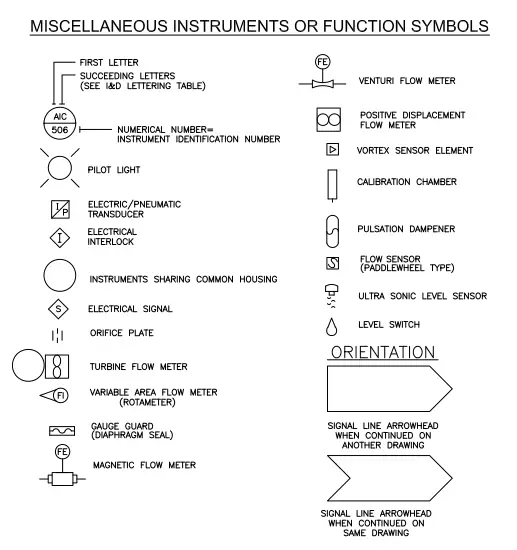
P&ID Symbols for Miscellaneous Instruments and Functions
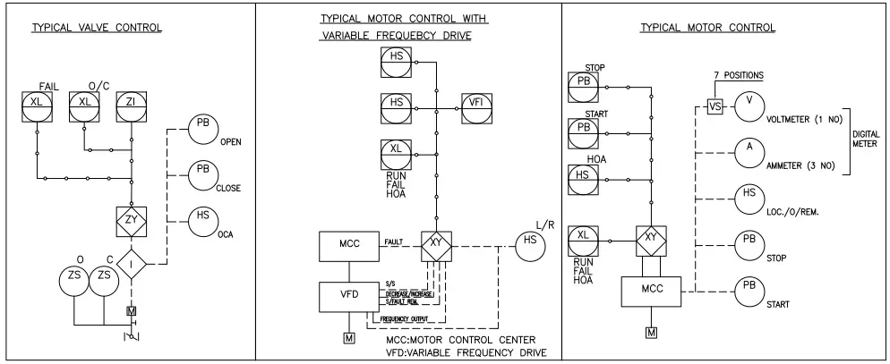
P&ID Symbols for Various Control Loops
Please note that few organizations use the words like P&ID Legends, P&ID Lead sheets, or P&ID Legend drawings in place of P&ID Symbols.
How to Read P&ID Drawings?
Reading or tracing a P&ID drawing to understand the process or design requirements are quite easy if the P&ID symbols are properly understood. So, it is always preferable to go through the P&ID symbols repeatedly, those are provided in the initial 4-5 pages of the P&ID sets. Once that is ready open the P&ID and start reading it.
Here, we will learn how to read P&ID with a simple example.
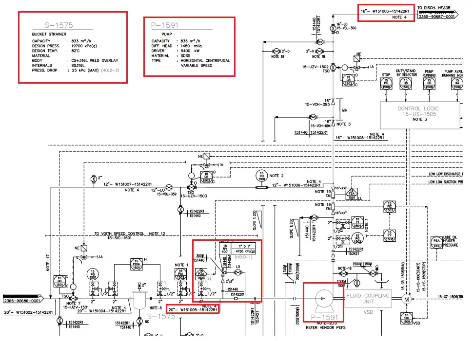
Refer to Fig. 8 which shows a part of a P&ID. We will read part of the suction and discharge line of pump P-1519.
- As can be seen clearly the suction line is coming from a different P&ID drawing and entering into the bucket strainer S-1575.
- The line number, pipe size, material spec, etc of the line are provided clearly.
- The line number changed from the strainer outlet, one PSV connection is attached before the pump suction reducer.
- After the reducer, the material specification is changed and then the line is connected to the pump suction flange.
- In a similar way, the pump discharge flange is connected to the discharge line, Line number, size, PMS, etc. are mentioned.
- So in a similar way, we can easily read the P&IDs as per our requirements and extract data to use for our purpose.
- Related notes are provided wherever required. We have to refer to those notes for knowing any specific requirements.
Difference between P&ID and PFD
Click here to learn about the major differences between a P&ID and a PFD.
Online Course on Piping & Instrumentation Diagrams P&IDs
If you feel the above information on P&ID is not sufficient and wish to know more details regarding piping & Instrumentation diagrams then click here to attend this 8-hour-long details P&ID online course.
Concepts and basics are explained very well. Very much useful for construction engineers, who are not much conversant with piping .
Thanks for sharing
It’s really a good read. I would request you to keep shAring such articles.
Excellent article dear Kumar. A great contribution of one of the products of great importance regarding the development of Engineering projects such as Piping and Instrumentation Diagrams.
Thank you very much for the technical contribution to the development of projects
Regards
Very good information
Dear Sir,
Your article is very good and useful.
Thank you.
There are some notes I would to share, if I may,
Prior to P&ID to be burn, BFD and PFD have to be generated. P&ID is a continuation or better yet is an expanding of PFD
WHY USE P&ID?
P&ID can also provide:
• Information on the type of fluid in the line,
• plus T&P will lead to the line design SPC
• Type of control system
• Battery limit
P&ID SYMBOLS
In addition to has been said, the PID symbols can be provided by individual specific operating company (owner) to engineering company (contractor) to use it in the project.
Finally, in reviewing P&ID, how to add, correct or delete, NOTES or drawing in existing P&ID.
Thank you
M. Benashur
P&d is a dynamic document which undergoes very critical reviews .As it is used by piping in particular and other disciplines while finalising their work , normal practice is to keep a master print of latest revision. All changes additions or deletions are marked. Periodically changes are transferred and given next revision number. It becomes clear which revision was used at various stages.
All satisfaction here.. Thank you🙏
piping and instrumentation diagram is most important document in piping process.it is also very helpful for new construction,maintenance activities,modification of piping system,shut down,isolation of piping and equipment’s and lot of other activities.
thanks for sharing information about p&id.
Great Post.
Excellent article Mr Kumar. Its help me to understand P&ID .
Wouldn’t P&ID translate to “Piping” and Instrumentation Diagram rather than “Process” as in includes pipng class information rather than process information. The PFD is dealing with process values.