
Piping systems are the backbone of many industrial processes, from oil and gas to water treatment and chemical manufacturing. Given their critical role, the integrity of these systems is paramount. Piping inspection is a systematic approach to ensuring that pipes and their associated systems are safe, reliable, and compliant with regulations.
What is Piping Inspection?
Piping Inspection is a comprehensive task that is performed following client/company-specific inspection documents. The main aim of the piping inspection is to ensure plant reliability, reducing probable errors, and thus safely operating the plant throughout its design life.
All plants are designed for a predetermined design life (normally 20 years for process piping). Periodic inspection help plants to operate with safety and efficiency.
Even after attending and completing various courses related to piping, most of the fresh graduates and professionals face difficulties in understanding the procedures when it comes to real-life jobs.
Considering the stigma, a simple way to understand the basic unique procedures that are to be followed during the fabrication and installation of carbon steel pipes is discussed in this article.
When it comes to piping it’s the Piping and Instrumentation Diagram or P & ID is the bible for an Engineer to execute his work.
Piping Inspection Procedure
For performing piping inspections, there should be a client-approved Inspection and Test Plan, or ITP, in place prior to the commencement of any job activities. This shall be prepared with reference to the piping design code and project specifications.
Piping design codes like ASME B31.3 PROCESS PIPING will be the design code for designing piping by the engineering team for the project.
Different types of design codes are available as per the project and product requirements. Understanding the codes and standards along with the particular project specification will provide basic ideas regarding the scope of work being executed.
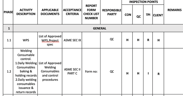
According to the requirements of the design code, the drawings will be developed and the same design code will be reflected in the drawings. All the construction procedures will be shortlisted with different intervention points as shown in the below Fig.1
What is the Inspection and Test Plan or ITP?
An ITP covers all the construction activities that are being carried out during and after the construction. Learning and understanding ITP along with the construction procedures and Method of statement for specific activities will give a wide range of understanding regarding the job being executed. The Inspection and Test Plan must meet the requirements of the design code (ASME B 31.3 for process piping).
Welding procedure specification or WPS shall be approved by the client prior to the commencement of any welding jobs. CSWIP and AWS-certified inspectors are preferred as inspectors or quality engineers for inspection-related jobs. Further to the approval of WPS welder qualification tests will be carried out based on the project requirements on the welding positions, process, and types. Only these welders who successfully pass the qualification test based on visual and Radiographic Testing reports can be used for all the project-related welding activities. Welder IDs signed by all parties shall be prepared and issued to the welder that shall be available with the welder during working hours.
Various certifications like API 570, API 650, Bgas, NACE, and Level 3 courses are available in the market to strengthen the requirements of a professional for a company.
Initially, after the approval of the above-said documents by the client, inspections shall be performed based on the ITP. No inspections or documents will be generated other than the ones mentioned in the ITP.
Inspection of Piping and Component Materials
Piping and Component Material inspection is the next step of inspection normally done by the quality personnel when a material related to the project is received at the site. The below points as a minimum are to be checked during the material inspection:
- Material purchased is from the client-approved manufacturer or vendor
- Material specification, grade, thickness, and size.
- Any mechanical damages.
- Heat numbers provided in the materials are matching with the Material Test Certificates provided prior to the inspection.
- Quantity of the material with reference to purchase order and delivery note.
- Reviewing of Material Test certificates with reference to project specification, design code, and drawings.
- Proper stacking of the materials.
Material inspection reports shall be generated with all the requested data like Material grade and type, quantity, Heat number, Material certificate number, and inspection status.
Once the materials are approved by the client it can be issued for construction.
Different Types of Piping Inspection
Fit-Up Inspection
Initially, the piping activities will commence with the fit-up inspection. This shall be carried out based on the approved isometric/weld map generated from the P&ID.
During the fit-up inspection, the joint number, date, spool number, drawing number, and sheet with revision shall be checked. The heat number of the material shall be noted for preparing the fit-up report. Taper gauge, Hi-lo gauge, cam gauge, and measuring tape will be used for checking the fit-up gap between the joints and for checking the dimension of spools. Further to the acceptance of fit-up the spool or joint can be released for welding.
Welding Inspection
Mostly GTAW and SMAW welding techniques are most commonly used for pipe welding. The welding inspections will be carried out in different stages by a certified welding inspector and the reports shall be generated with material grade and specification, heat number, drawing number with sheet number and revision, joint type, welding process, welder number, and dates.
Once the joints are completed will proceed with the RT i.e, radiography testing as per the percentage of NDE recommended in the design code and project specification.
Piping routing consists of elbows and fittings. Other than the weld joints flanged joints will be available based on the engineering requirements considering the stress analysis. Pipe supports and wear pads along with any other attachments shown in the drawings shall be checked twice.
Visual Inspection
Visual inspection is the most fundamental type of inspection. It involves examining the exterior of pipes for signs of wear, corrosion, leaks, and other visible defects. While it cannot detect subsurface issues, it is a valuable first step in identifying potential problems.
Destructive Testing
In certain scenarios, destructive testing may be necessary to evaluate the material properties of piping. This includes tensile testing, impact testing, and metallurgical analysis. While it provides detailed insights, it is not commonly used for routine inspections due to its invasive nature.
Piping Inspection Punch Lists
Once the welding activities and installation of piping spools or the system are completed a pre-hydro walkthrough will be conducted in order to find the balance/pending jobs. These are normally considered punches that are commonly grouped into two types, punch A & punch B. Punch A items consist of direct welding items, and punch B can be closed after the hydro tests. No direct welding shall be done in the piping system after the completion of hydro testing.
Hydro-test Package
After attending the punch A items, the spools can be released for hydro testing. A test package shall be prepared, not limited to the below-listed items.
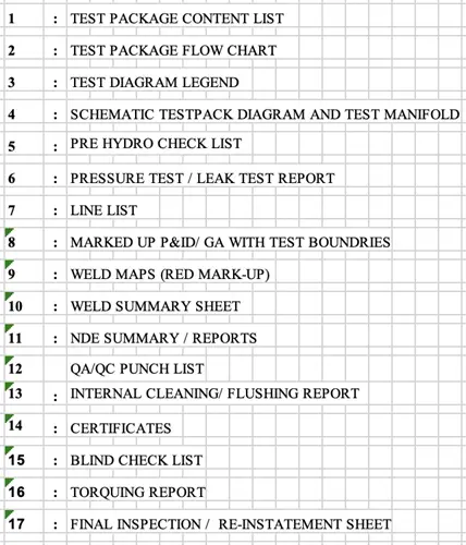
The test pressure and holding time will be confirmed subject to the project specification and design code.
Water will be filled into the pipe spools with a pump connected through a test manifold with pressure gauges, safety relief valves, and proper venting facilities. A water test certificate shall be attained prior to the filling of water along with the blind checklist, i.e. the list of blind flanges that are being used for hydro testing.
Understanding the above list will provide a basic idea regarding the hydro test.
Note that a hydro test is done in order to confirm the weld joints’ integrity and to ensure that the parent material is free of any leakage.
Bolt tightening with a torque wrench shall be done for the flanged joints. After draining the water, flushing the lines with water and air blowing shall be done in order to dry the lines.
Note that valves are not installed prior to the hydro test, inline valves are installed after the hydro test and cleaning process as the testing pressure and design code for valves are different.
The spools or piping system can now be released for blasting and painting as per the project requirements. A final walkthrough shall be conducted in order to confirm the installation of all the valves and instruments in the piping system are in place as per the P&ID.
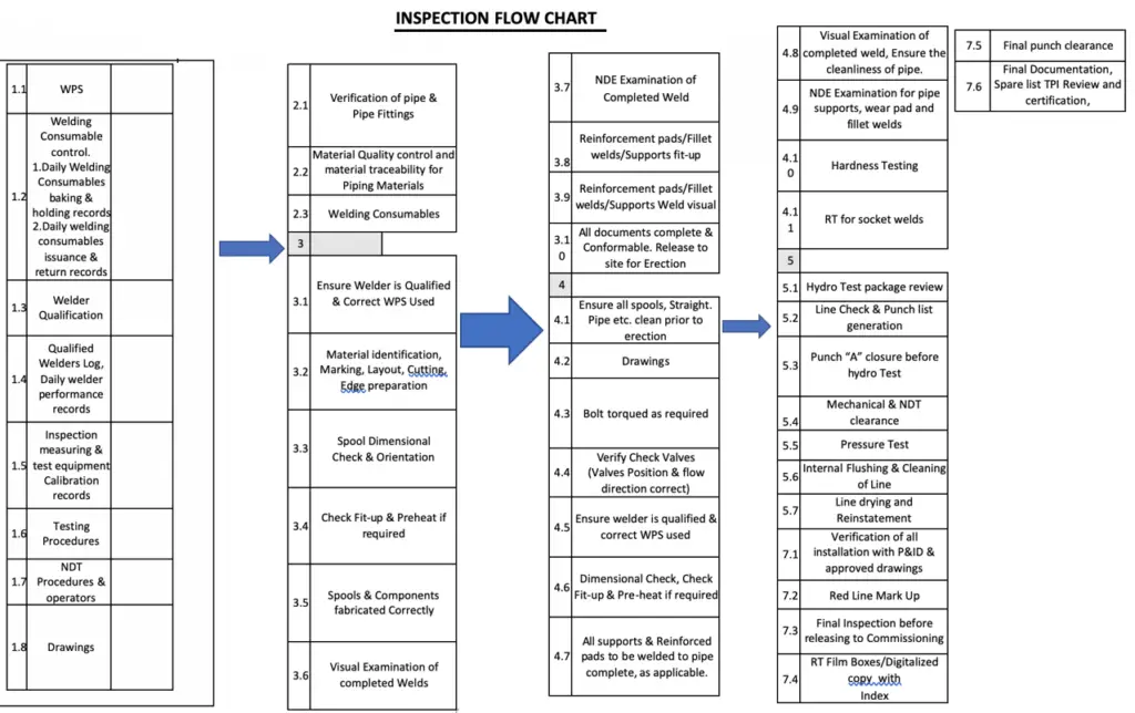
Piping Inspection Flow Chart
The following figure shows a sample piping inspection flow chart.
Codes and Standards for Piping Inspection
There are various international codes and standards that provide guidelines for piping inspection. Some of those codes are listed below for reference:
- API 570, Piping Inspection Code
- API RP 574, Inspection Practices for Piping System Components
- API RP 577 Welding Inspection and Metallurgy
- API RP 578, Material Verification for New and Existing Alloy Piping
- API RP 583, Corrosion Under Insulation and Fireproofing
- ASME PCC-2, Repair of Pressure Equipment and Piping
- ASTM STP 880, Corrosion of Metals Under Thermal Insulation
- API RP 571 Damage Mechanism Affecting Fixed Equipment in the Refining Industry
Developing an Inspection Program
Risk Assessment
A thorough risk assessment identifies potential hazards associated with piping systems. This process helps prioritize inspection efforts based on factors like system criticality, operating conditions, and historical data.
Inspection Schedule
Developing a comprehensive inspection schedule is crucial for maintaining piping integrity. Factors to consider include:
- Age of the system
- Operating conditions
- Type of fluid transported
- Previous inspection results
Documentation and Reporting
Maintaining detailed inspection records is essential for compliance and future reference. Inspection reports should include:
- Inspection methods used
- Findings and measurements
- Recommendations for repairs or further action
- Follow-up inspections and timelines
Common Piping Defects and Their Causes
Corrosion
Corrosion is one of the most significant threats to piping integrity. It can be caused by:
- Chemical reactions: Interaction of the pipe material with transported fluids.
- Environmental factors: Moisture, temperature fluctuations, and soil conditions can accelerate corrosion.
Cracking
Cracks can result from stress, fatigue, or improper installation. Common types include:
- Stress corrosion cracking (SCC): Caused by the combined effects of tensile stress and a corrosive environment.
- Fatigue cracking: Resulting from repeated loading and unloading cycles.
Leaks
Leaks can occur due to several factors, including:
- Worn-out seals and gaskets
- Erosion from fluid flow
- Improperly installed fittings or connections
Mechanical Damage
Mechanical damage can arise from external forces, such as impacts from equipment or natural events (e.g., earthquakes). Regular inspections can help identify and mitigate these risks.
Hope, the above-mentioned details will provide some basic ideas to beginners regarding the sequence and structure of piping inspection. Overall, piping inspection is a critical component of maintaining the safety and reliability of piping systems across various industries. By understanding the importance of inspections, employing the right methods, and adhering to industry standards, organizations can mitigate risks and ensure the longevity of their piping systems.
Can u share me please?
sure,but what exactly ur seeking for?
Very well!!!
Hi Anup.
Which standard do you make reference to regarding Piping Inspection Punch Lists ??
Thanks for the reminder that proper welding is also one of the important things to look into when planning to get a piping fabrication service. I’m interested in getting into the food industry soon so I want to start knowing more about the kinds of things needed for the construction of facilities for them. That way, I will be able to avoid making mistakes in the future.