
A pressure vessel nozzle is an opening in the pressure vessel through which fluid enters or exits the pressure vessel. The Nozzle, in general, projects from the pressure vessel’s surface and ends with a means of joining (flanged or welded) piping or equipment. To carry the normal process or operation of the pressure vessel these nozzle connections are required. The main functions of a pressure vessel nozzle opening can be any of the following:
- To allow the content to move into the vessel or away from the vessel to help further processing of the fluid.
- To allow the insertion of instrument items.
- To allow for inspection or access to internal parts (Manholes).
To connect the nozzle with the pressure vessel, an opening is made in the vessel which in turn results in penetration of the pressure retaining wall. So, it weakens the boundary creating a discontinuity in the pressure vessel wall. Nozzle openings can be made in the shell or head parts of the pressure vessel. In this article, we will study the main types of pressure vessel nozzles used in process plants, their allowable loads, and some nozzle design points.
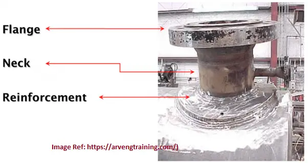
Parts of a Pressure Vessel nozzle
A pressure vessel nozzle consists of three parts
- A flange Connection (for flanged connection with pipe)
- Nozzle Neck part and
- Reinforcement (in case required)
Types of Pressure Vessel Nozzles / Pressure Vessel Nozzle Types
From a broad perspective, pressure vessel nozzles are classified into two groups.
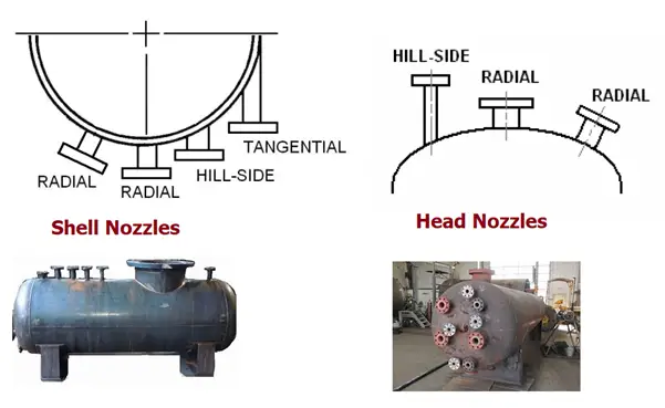
- Radial Nozzle (Fig. 2) and
- Non-Radial Nozzle (Fig. 2)
- Hill Side Nozzle and
- Tangential Nozzles
- Angular Nozzles
Depending on the location of the nozzles they are grouped as
- Shell Nozzles (Fig. 2) and
- Head Nozzles (Fig. 2)
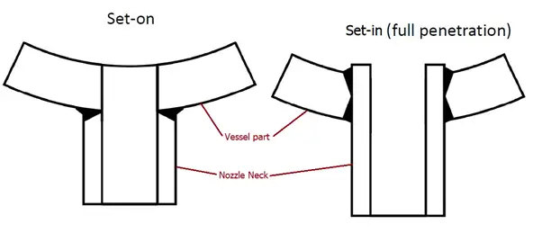
Again, depending on the welding and positioning of the nozzles two types of nozzles are widely known.
- Set-in Nozzle (Fig. 3): Nozzle is projected inside the vessel surface. The pressure vessel opening diameter in the shell/head coincides with the outer diameter of the neck.
- Set on Nozzle (Fig. 3): Nozzle is seated on the vessel. The diameter of the pressure vessel opening in the shell or head coincides with the ID (inner diameter) of the nozzle neck.
Depending on the Reinforcement requirement of the pressure vessel nozzles, two types of nozzles are used
- Nozzles with added reinforcement: Additional reinforcing plate is added to withstand external nozzle loading. Preferred for non-cyclic loads.
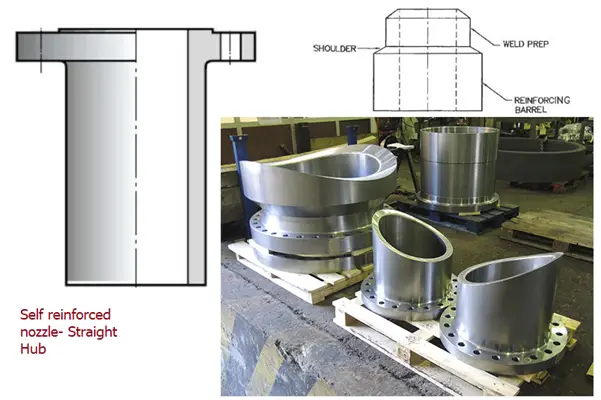
- Self-reinforced nozzles: Nozzle thickness itself is sufficient to withstand external nozzle loads and so an additional RF pad is not provided. Preferred for fatigue or cyclic loading. They are of two types:
- Nozzles with straight hub
- Nozzles with variable hub
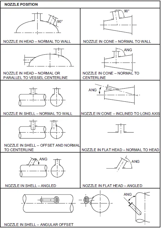
Also, the nozzles in a pressure vessel can be placed perpendicular or angular position with respect to the shell axis. It can be intersecting the vessel axis or offset. Various nozzle positions are shown in Fig. 5.
Allowable Nozzle Loads
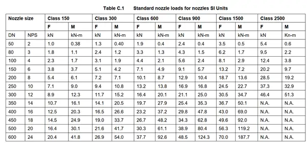
Allowable nozzle loads for pressure vessels are provided by manufacturers. Normally, engineering companies have their own specification to decide minimum nozzle loads with respect to connected pipe size and flange rating. A similar pressure vessel nozzle loading table for vessels made from ferrous material from shell DEP 31.22.00.31 (unfired pressure vessel) is produced below (Fig. 6) as a sample.
Click here to know more about using standard pressure vessel allowable nozzle load tables.
From the above table the following conclusions can be made:
- With an increase in flange rating, the nozzle load-carrying capability increases.
- With an increase in nozzle size the load-carrying capability increases.
The capability of a vessel to withstand the external nozzle loading is decided based on WRC or FEA calculations. WRC calculation can be done using Caesar II, PV-elite, Start-Prof, or Code-cal software. FEA calculation can be done using Nozzle-pro, Nozzle-FEM, or Ansys software.
Design of Pressure Vessel Nozzles
For the design of Pressure Vessel nozzles, various codes and standards are available. However, the most widely used internationally recognized ASME BPVC Section VIII by the American Society of Mechanical Engineers (ASME).
Other pressure vessel codes and standards that are occasionally used are:
- Europe: EN-13445
- United Kingdom: British Standards BS PD 5500
- France: CODAP
- China: GB-150
- Germany: A. D. Merkblatt Code
Nozzle design basically means three parts:
- Deciding the nozzle size or nozzle opening
- Designing and Selecting Nozzle thickness and
- Calculating the reinforcement requirement based on pressure and external loads.
The size of the nozzle opening is normally decided by the process team depending on the volume of fluid input and output in the pressure vessel. Once the nozzle opening size is fixed the nozzle thickness requirement is calculated based on the design pressure of the contained/flowing medium. The calculated thickness is normally converted into standard nozzle thickness as per standard pipe thickness available following ASME B36.10 or ASME B36.19 standards. In the next step, the requirement of nozzle reinforcement is checked.
The design of pressure vessel nozzles is done following equations mentioned in ASME Section VIII, Div. 1 UG 36 to UG 45.
Nozzle design Calculation for pressure vessels is normally performed following the area compensation method. The detailed nozzle design methodology is explained in the following article: “Nozzle Reinforcement Calculation for a Cylindrical Nozzle“
Online Course on Pressure Vessels
If you wish to learn more about Pressure Vessels, their design, fabrication, installation, etc in depth, then the following online courses will surely help you:
Very well explanation sir.
Regards,
Yeremi
Thank you for your clear explanations.
Minh Nguyen
Dear,
Hi,
First of thanks a lot for a vital and useful information.
I am a Principal Mechanical (Static) Designer.
Please provide all points/Check List before preparation of GAD and Fabrication drgs. of pressure Vessels including Exchange drgs.
TIA
Well written, informative, good pictures add to value to the article.
Nice Explanation and worthful to learn…
As always our man Anup comes thru!
What sizes of nozzles can you add to a pressure vessel without doing calculations.
Repair versus Alteration which requires calculations.
really good initiative
Gr8
Greetings, Well written along with good pictures and in proper sequences. And refreshed my knowledge again. Thank you so much
Regards, Davudali NADAF
Keep up the good work…….
Good afternoon, excellent explanation, I just have one question. I am evaluating a 2″ diameter set-in (full penetration) radial nozzle without additional reinforcement, which is made up of: Nozzle neck, 90° elbow, pipe spool and class 600 flange, said nozzle is connected to the level leg, I have an internal corrosion problem in the 90° elbow so my question is whether the thickness that governs all pipe components with the exception of the flange is UG-45 or does it only apply strictly to the neck of the nozzle? If so, for the 90° elbow and the pipe spool attached to the flange, you could calculate it with UG-27 or UG-45 also applies?