
A Heat exchanger is a device to transfer heat from one fluid (Liquid/Gas) to another. There are various types of heat exchangers used in process piping. Shell and Tube heat exchanger is the most common type of heat exchanger. This article will provide you with a guide to everything you need to know about shell and tube heat exchangers. The major topics covered in this article are:
- Definition of Shell and Tube Heat Exchanger
- Working Principle of Shell and Tube Heat Exchanger
- Basic Components and Parts
- Types of Shell and Tube Heat Exchanger
- Codes and Standards for Shell and Tube Heat Exchangers
- Design of Shell and Tube Heat Exchangers
- And much more.
What is a Shell and Tube Heat Exchanger?
Shell and tube heat exchanger (STHE) is the most widely used heat exchanger and is among the most effective means of heat exchange. A shell and tube heat exchanger is a device where two working fluids exchange heat by thermal contact using tubes housed within a cylindrical shell. The fluid temperature inside the shell and tube are different and this temperature difference is the driving force for temperature exchange. Used for wide temperature and pressure ranges, Shell and tube heat exchangers are compact in design, easy to construct and maintain, and provide excellent heat exchange.
As the name specified, it consists of a shell and a number of tubes. The shell is the housing of the exchanger and tubes are mounted inside the cylindrical shell.
Working Principle of Shell and Tube Heat Exchanger
The working of a shell and tube heat exchanger is fairly simple. One fluid flows inside the tubes and the other through the shell. While flowing they exchange heat which means the cold fluid gains the heat from the hot fluid. So one cold fluid enters the shell (or tube side or channel side) inlet nozzle and comes out of the outlet nozzle as hot fluid. Obviously, the other fluid will become colder in the outlet than in the inlet. The heat transfer in a shell and tube heat exchanger is determined by the exposed surface area and is decided by the number of thermally conductive metal tubes. The fluid flow inside the shell and tube heat exchanger can be parallel flow or crossflow.
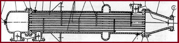
Fig 1 shows the typical working principle of a shell and tube heat exchanger.
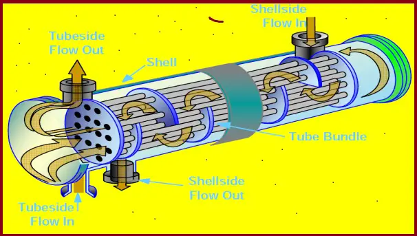
The above figure shows both the inlet and outlet nozzle in the front header of the channel side. That means this exchanger consists of an even number of tube passes. However, there can be an odd number of tube passes. In that situation, the channel side outlet nozzle will be on the read header. Increasing the number of tube passes increases the heat transfer coefficient.
To increase the fluid turbulence in the tube and shell side flow, turbulators and baffles are installed inside tubes and shells respectively. This increases the heat transfer between the fluids.
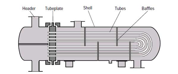
Basic Components of Shell and Tube Heat Exchanger
Typically a Shell and Tube Heat Exchanger consists of two-compartment / sections; one is shell side and the other is channel/tube side
- The shell side section consists of the following components: Shell, Cover, Body Flange, Nozzles, and Saddle support.
- Channel / Tube side section consists of the following components: Channel, Cover, Body Flange, Nozzles, Tube Sheet, and Tubes (Tube Bundle)
The heat exchanger is supported by saddles in the shell part.
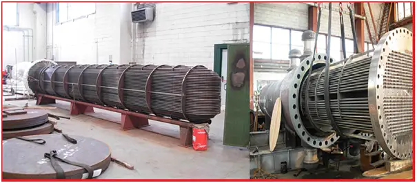
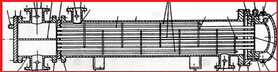
Tube Bundle of Shell and Tube Heat Exchanger
Tube Bundle (Fig. 3) consists of the following components
- Tube sheet
- Tubes
- Baffles
- Tie rods and Spacers
- Sliding strips
Tube bundles are removed during maintenance. Standard practice is to flow the corrosive fluid inside the tubes so that if corroded they can be easily replaced or repaired. Fig. 3 below shows a typical tube bundle.
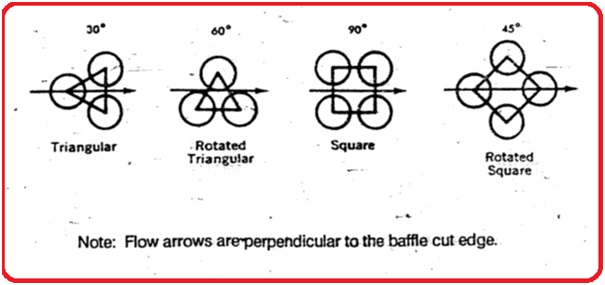
Tube Pattern inside Shell & Tube Heat exchanger
Normally tubes inside the exchanger are 0.5″ to 2″ in size and arranged in triangular or square patterns as shown in Fig. 4
Tube Pitch
The tube shall be placed with a minimum center-to-center distance of 1.25 times the tube outside diameter of the tube. When mechanical cleaning of the tube is specified then a minimum cleaning lane of 6.4 mm shall be provided.
Baffles
Baffles are installed in the shell of the shell and tube heat exchanger to create more turbulence and increase the flow time so that better heat exchange is possible. Baffles support the tubes so that damage and vibration of tubes are minimized.
Types of Shell and Tube Heat Exchangers
TEMA shell and tube heat exchanger types based on application
As per TEMA (Tubular Exchanger Manufacturers Association) Shell and Tube Heat Exchanger can be classified as
- Class R Exchangers – Refinery and Petrochemical Application
- Class C Exchangers – General Process Application
- Class B Exchangers- Chemical Process Application
TEMA Shell and Tube Heat Exchanger Applicable Criteria
- Inside diameter less than 2540 mm (100 inches)
- Product of nominal diameter (mm) and design pressure (kPa) of 17.5 x 10⁶
- Design pressure of 3000 psig (20684 KPa)
The reason behind such limitation is to keep the maximum shell wall thickness below 3 in. (76 mm), and the maximum stud diameter below 4 in. (102 mm).
Shell and Tube heat exchanger types based on construction
Depending on various construction and configuration parameters following types of shell and tube heat exchangers are widely used in industries.
Fixed Tube Sheet Heat Exchanger
The tube sheet is fixed in the shell by welding and hence the term fixed tube sheet exchanger applies. This simple and economical construction allows the cleaning of the tube bores by mechanical or chemical means. An expansion bellow is installed in the shell when there is a large temperature difference between the shell and tube materials. Refer to Fig. 5 for an example of the fixed tube heat exchanger.
Floating Head Heat Exchanger
In floating head construction, the rear header can float or move as it is not welded to the shell. The tube bundle can easily be removed during maintenance. Fig. 6 shows an example of a floating head heat exchanger.
Stationary Tube sheet with removable tube bundle
Fig. 7 shows an example of a stationary tube sheet with a removable tube bundle.
U-tube Heat exchanger
U-tube exchangers are a type of shell and tube heat exchanger whose tube bundle is made of continuous tubes bent into a “U” shape. The bend side is free-floating and this helps in thermal expansion without requiring expansion joints. However, such bends are difficult to clean.
Based on the number of times the tube-side/shell-side flows pass through the exchanger, the shell and tube heat exchanger is categorized as:
- Single-Pass exchangers and
- Multi-Pass exchangers
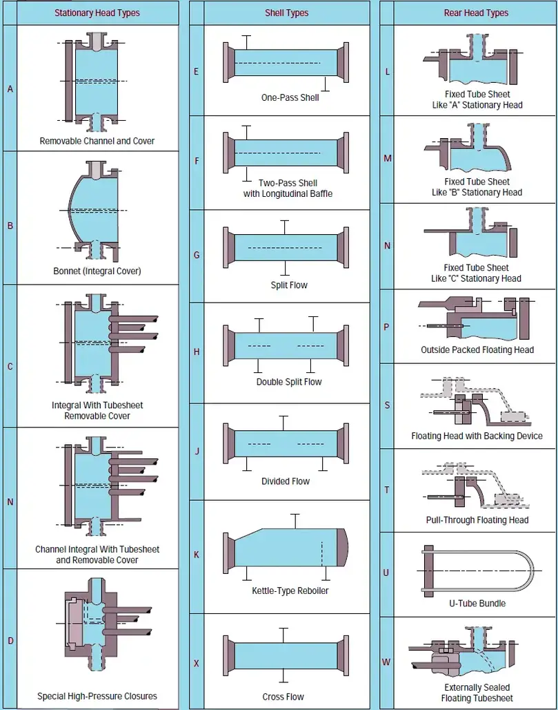
The full TEMA classification of shell and tube heat exchanger types is provided in Fig. 9 below:
Depending on the application of shell and tube heat exchangers, they are known as various types as listed below:
- Reboilers
- Evaporators
- Condensers
- Aftercoolers
- Preheaters, etc.
Stack Types of Configuration
In this, two or three heat exchangers are placed one above the other. This is termed as 1 shell in parallel and 2 or 3 Shells in series. Refer to Fig. 10.
Codes and Standards for Shell and Tube Heat Exchangers
The following codes and standards govern the design of shell and tube heat exchangers.
- API 660 ( Shell and Tube heat exchangers for general refinery service)
- ISO 16812
- ASME SECT.VIII Div.1 (UHX) or Div.2
- PD 5500
- EN 13445
- AD 2000 Merkblatt.
- TEMA -Tubular Exchanger Manufacturers Association
- Shell DEP 31.22.20.31 and DEP 31.21.01.30
Design of Shell and Tube Heat Exchangers
Process Design of Shell and tube Heat exchanger
The design of the Shell and tube heat exchanger is a trial-and-error iterative process. In recent times, thermal design has been carried out by the process team using engineering software. However, the logic behind the calculations should be clearly understood. The shell and tube heat exchanger design calculations are based on the initial selection of a preliminary exchanger configuration and certain initial decisions like
- the front and rear header type,
- shell type,
- the sides the fluids are allocated,
- baffle type and baffle pitch
- tube diameter, length, and tube layout
- shell diameter, and
- number of tube passes
Further steps for the shell and tube heat exchanger design consist of
- Calculation of shell side flow distribution and heat transfer coefficient
- Estimation of tube side heat transfer coefficient and pressure drop
- Determination of wall resistance and overall heat transfer coefficient
- Calculation of Mean temperature difference (log mean temperature difference) from the inlet and outlet temperatures of the two fluids.
- Estimation of the required heat transfer area
- Comparison of the calculated area with the assumed geometry
- Comparison of shell and tube-side pressure drop with allowable pressure drop
- If the pressure drop is within the allowable pressure drop design is acceptable. Otherwise, adjust the assumed geometry and repeat the above steps.
Once the requirements are met, a process datasheet is developed indicating all process design parameters of shell and tube heat exchanger design.
General design Considerations for shell and tube heat exchanger
Fluid Allocation: Shell Side vs. Tube Side
The following table (Table 1) provides general guidelines for shell and tube side fluid allocation in a shell and tube heat exchanger:
| Fluid Parameters | Fluid Allocation-Shell Side | Fluid Allocation-Tube Side |
| High-Pressure Fluid Stream | X | |
| Corrosive Fluid | X | |
| High-fouling fluid stream | X | |
| More Viscous fluid | X | |
| Lower Flow Rate Fluid | X | |
| Fluid with a low heat transfer coefficient | X | |
| Toxic Fluid | X |
Fluid Velocity inside Shell and Tube
High fluid velocities increase heat transfer coefficients and reduce fouling but cause erosion and increase pressure drop. So velocity selected should be just enough to prevent the settling of suspended solids. Typical fluid velocities considered for the design of shell and tube heat exchangers are given in the following table (Table 2):
| Fluid Types | Fluid Velocity-Shell Side | Fluid Velocity-Tube Side |
| Liquid | 0.3 to 1 m/s | 1 to 2 m/s |
| Gas /Vapor (Vacuum Pressure) | 50 to 70 m/s | 50 to 70 m/s |
| Gas /Vapor (Atmospheric Pressure) | 10 to 30 m/s | 10 to 30 m/s |
| Gas /Vapor (High Pressure) | 5 to 10 m/s | 5 to 10 m/s |
Pressure Drop Consideration
Typical pressure drop values considered for shell and tube heat exchanger design are:
- For Liquids with Viscosity<1 mN-s/m2, ΔP=35 kPa
- For liquids with Viscosity=1 to 10 mN- s/m2, ΔP= 50-70 kPa
- Liquids without phase change= 70 kPa
- Condensing streams= 14 kPa
- For Vapor and gas services:
- High vacuum Pressure: 0.4-0.8 kPa
- Medium vacuum Pressure: 0.1 x absolute pressure
- Pressure 1 to 2 bar: 0.5 x system gauge pressure
- Pressure above 10 bar: 0.1 x system gauge pressure
- Vapors without phase change= 14 kPa
- Boiling Streams = 7 kPa
Software used for Thermal Design
The most popular software used for the thermal design of shell and tube heat exchanger are listed below
- HTRI – Heat Transfer Research Institute
- HTFS – Heat Transfer Research and fluid flow service
Mechanical design of Shell and Tube Heat exchanger
Mechanical design of shell and tube heat exchangers consists of calculation of shell thickness, flange thickness, etc. Various codes like ASME Sec VIII, PD 5500, TEMA, etc. provide guidelines for mechanical design. The following design guidelines can be followed:
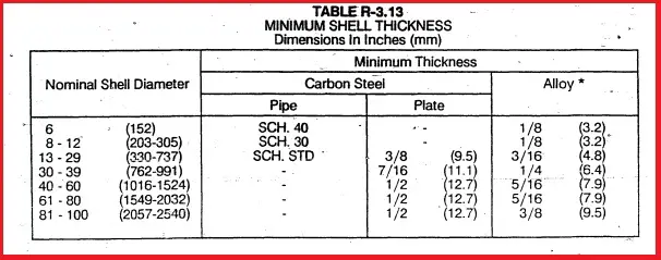
- Minimum Shell Thickness (Fig. 11) as per TEMA for Class – R
- Baffle clearance, Baffle spacing, and thickness as per TEMA table RCB -4.3
- Tie rod size and nos. as per TEMA table R- 4.71 for class – R
- Peripheral Gasket: The minimum width of the peripheral ring gasket for external joints shall be 10 mm for shell sizes up to 584 mm and 12 mm for all larger shell sizes.
- Pass Partition Gasket: The min. width of the gasket web for the pass partition of the channel shall not be less than 6.4 mm for shell sizes up to 584 mm and 9.5 mm for all larger shell sizes. The gasket joint shall be confined type
- Shell and Head design is done as per selected Pressure Vessels Design Code such as ASME, EN, or AD
- The most widely used design code across the world is ASME Sect. VIII Div.1 & 2
- Body / Girth Flange Design as per Appendix -2 of ASME Sect. VIII Div.1
- The tube sheet design is Mandatory as per UHX of ASME Sect. VIII Div.1
- The tube sheet is designed for the following three cases.
- Tube side pressure (Pt) acting and Shell side pressure (Ps) is Zero
- Shell side pressure (Ps) acting and Tube side pressure (Pt) is Zero
- Shell side pressure (Ps) acting and Tube side pressure (Pt) acting
- Please consider the effect of Vacuum in the above load cases
- Tube sheet Design formula based on the theory of Flat Plates
Shell and Tube Heat Exchanger Material of Construction (MOC)
The following materials are the most common as Shell and Tube Heat Exchanger MOC.
- Carbon steel and Cladding Plates
- Stainless Steel
- Duplex Stainless steel
- Tubes – Carbon steel, Stainless steel, Duplex stainless steel, Exotic material such as copper, Inconel, Titanium
Maintenance of Shell and Tube Heat exchangers
Depending on user experience and manufacturer guidelines, shell and tube heat exchangers should be inspected at regular intervals. A shell and tube heat exchanger can fail by one or more of the following factors:
- Improper design.
- Excessive fouling.
- Air or gas binding resulting from improper piping installation or lack of suitable vents.
- Excessive clearances between the baffles and shell and/or tubes, due to corrosion.
- Operating conditions differ from design conditions.
- Maldistribution of flow in the unit, etc
Following preventive maintenance steps at regular intervals can reduce the risk of equipment failure. Following maintenance steps can be followed to enhance shell and tube heat exchanger performance:
- Cleaning periodically to avoid fouling
- Inspection of tubes
- Gasket replacement
- Repairing leaks if detected during inspection.
Application of Shell and Tube Heat Exchangers
Shell & Tube Heat Exchangers find their application in the following Industries-
- Refinery and Petrochemical
- Fertilizer
- Oil and Gas
- Chemical
- Power Plants
Advantages of Shell and Tube Heat Exchanger
Shell and tube heat exchangers are widely used in various industrial processes due to their numerous advantages. These advantages make them a preferred choice for many applications where efficient heat transfer is essential. Here are some of the key advantages of shell and tube heat exchangers:
High Heat Transfer Efficiency: Shell and tube heat exchangers are known for their excellent heat transfer capabilities. The design, which features a large surface area for heat exchange, allows for the efficient transfer of thermal energy between the fluids. This results in rapid heating or cooling, making them highly efficient in heat transfer applications.
Versatility: Shell and tube heat exchangers are versatile and can handle a wide range of fluids, including gases and liquids. They can be used for both heating and cooling processes and are compatible with various industries, including chemical processing, power generation, food and beverage, and HVAC systems. They are available in a range of configurations to suit various operations.
Robust and Durable Construction: These heat exchangers are typically built with materials like stainless steel, copper, or titanium, which offer excellent resistance to corrosion and wear. This durability ensures a long operational lifespan, reducing maintenance and replacement costs.
Ease of Maintenance: Shell and tube heat exchangers are relatively easy to maintain. The tube bundle can be accessed and cleaned or replaced without the need to disassemble the entire unit. This feature minimizes downtime and reduces maintenance costs.
Compact Design: Despite their high efficiency, shell and tube heat exchangers have a compact design, which is particularly beneficial in applications with limited space. Their compactness allows for efficient heat transfer within a relatively small footprint.
High Pressure and Temperature Capabilities: Shell and tube heat exchangers are capable of handling high-pressure and high-temperature applications. This makes them suitable for use in industries such as oil refining and chemical processing, where extreme conditions are common.
Customizable Configurations: These heat exchangers can be customized to meet specific requirements. Engineers can adjust the number of tubes, tube diameter, tube arrangement, and other design parameters to optimize performance for a particular application.
Resistance to Fouling: The design of shell and tube heat exchangers often includes baffles and turbulence-inducing features, which help reduce fouling by preventing the buildup of deposits on the tube surfaces. This resistance to fouling ensures consistent heat transfer efficiency over time.
Long Service Life: When properly maintained, shell and tube heat exchangers can have a significantly long service life, making them a cost-effective investment for industries that rely on continuous heat exchange operations.
Energy Efficiency: Their high heat transfer efficiency translates into energy savings. Shell and tube heat exchangers can help reduce energy consumption in processes that require heating or cooling, contributing to overall operational cost reductions.
Disadvantages of Shell and Tube Heat Exchanger
While shell and tube heat exchangers offer numerous advantages, they also have some disadvantages and limitations. It’s essential to consider these drawbacks when selecting a heat exchanger for a specific application. Here are some of the disadvantages of shell and tube heat exchangers:
- High Initial Cost
- Large Footprint
- Limited Heat Transfer for Low Temperature Differences
- Limited Turbulence
- High Pressure Drop
- Fouling and Scaling
- Weight Considerations
Few more resources for You..
Shell & Tube Heat Exchanger Piping: A brief Presentation
An article on Plate Heat Exchanger with Steam
A typical Check List for Reviewing of Shell & Tube Heat Exchanger Drawings
A brief presentation on Air Cooled Heat Exchangers
Basic Considerations for Equipment and Piping Layout of Air Cooled Heat Exchanger Piping
Reboiler Exchanger and System Type Selection
Congratulations.
Very good presentation.
Thanks.
Need some focus on expansion bellows.
What I like the most about the shell & tube design compare to other type like plate and frame or helicoil is that despite the fact they are built to last for a longer life is:
1- The tube bundle is easy to replace because you have just one or 2 gaskets to replace
2- They are easy to repair a tube temporary by plugging it for a fast restart of the process while waiting for the next shut down
3- If you need to clean the tubes, you can easily see from your eyes if the tubes are clean enough.
4- For high scale application their is the possibilty to add an automatic brush in each tube to avoid any scale or plug tube.
In steam application I suggest to use a vertical shell & tube design to flood the heat exchanger.
Congratulations
Great presentation with very easy explanation to understand the fundamentals of heat exchanger
Thank you
Very good presentation and very Informative.
Very Nice Presentation. Can we see any operation and maintenance guide for Shell & Tube type heat exchanger
Congratulations
Very good prasentation .sir ..
Very Nice Presentation
Thanks for a detailed information.
Requesting you to also describe details related to its piping arrangement. Guidelines to be taken if the heat exchanger is located on the ground or on platforms above.
Interesting
Congratulations.. Good presentation Sir
Congratulations sir and very good presentation of Heat exchanger
Hi Anup. Very Good presentation.
Do you have a presentation on maintenance of shell tube heat exchangers?
I would like to strengthen aspects such as:
– Recommended gaskets for service
– recommended torque and / or tensioning
– Hydrostatic tests on high pressure equipment on both sides.
API 660, API 572 and ASME PCC-2 offer help, however I would like to know your opinion.
Thank you
best regards
Norton
Congratulations Good presentation thanks
Very good presentation
Good explanation
Thanks for this presentation.
Do you know or have any write up that can help me to know the size of the heat exchanger that i can use for some specified inlet and outlet pressure and temperature
congratulation ,,, this is very nice presentation
Verry Good sir
Very good presentation . Thanks lot
I am amazed by your expertise and hope to make friends with you and discuss thermal science together