
Shell & Tube Heat Exchangers are the most frequently used Heat Exchangers in Process Plants. The purpose of this presentation is to provide guidelines for Shell & Tube Heat Exchanger Piping Layout. Click here to get a preliminary idea about shell and tube heat exchangers.
Use of Shell & Tube Heat Exchangers
All Heat exchangers are used to transfer heat from one fluid to another. They are generally named as coolers, chillers, condensers, heaters, reboilers, waste heat boilers, steam generators & vaporizers in the process plant.
Types of Heat exchangers
The most commonly used types of heat exchangers are
- Shell & Tube heat exchanger
- Air-cooled heat exchanger
- Plate-type heat exchanger
- Spiral heat exchanger
- Double pipe heat exchanger
Shell & Tube Heat Exchanger Construction (Fig. 1)
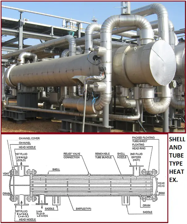
These heat exchangers are generally designed, fabricated, inspected, and tested as per API 660 / EN-ISO 16812 / TEMA. The DEP for the design & construction of the shell & tube heat exchanger is DEP 31.21.01.30 – Gen.
General Guidelines for selection for tube side & shell side fluids:
- Clean fluid through the shell & dirty fluid through tubes.
- Corrosive fluid through tubes as it is easy for cleaning & allows the use of carbon steel for the shell.
- Water through shell & process liquid through Only seawater through the tube side.
- High-pressure fluid through tubes which allows for min. the wall thickness of the shell.
The layout of shell & tube heat exchangers other than in banks
As per the exchanger positions in a process plant, the following general classification can be made:
- Exchangers which should be next to other equipment: e. g. Vertical Reboiler
- Exchangers which should be close to other equipment: e. g. Overhead condenser
- Exchangers located between other process equipment: e. g. The exchanger with process lines connected to both the shell & tube side
- Exchangers located between process equipment and the unit limit:e.g. Product coolers
Establishing elevations for the exchanger
- Where process requirement dictates the elevation, it is usually noted on the P&ID/PEFS
- The grade is the best elevation from an economic point of view
- Located in structures where gravity flow is required or connected to pump suction which has specific NPSH requirement e.g. overhead condenser
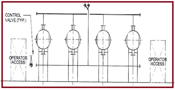
The layout of Shell & Tube heat exchanger in banks
Arrangement of exchangers (Fig. 2):
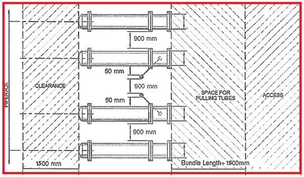
Various types of Exchanger orientation are possible as mentioned below:
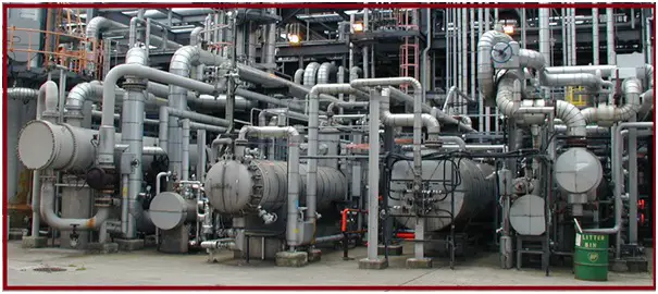
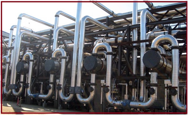
Sample exchanger orientation (Fig. 3)
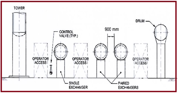
Single and Paired Exchangers (Fig. 4)
Parallel Exchanger Installation (Fig. 5)
Series Exchanger Installation (Fig. 6)
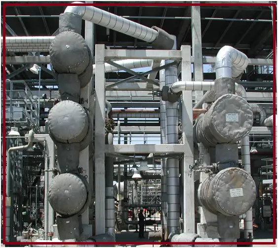
Stacked exchanger installation
Two exchangers in series or parallel are usually stacked. Refer Fig. 7
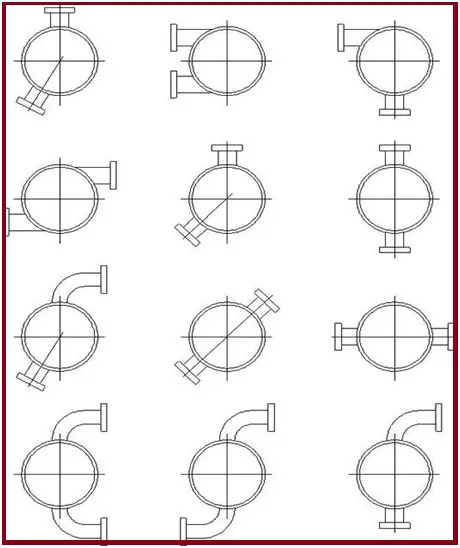
Nozzle arrangement for better piping (Fig. 8)
Structure-mounted exchanger installation (Fig. 9)
Supporting shell & tube heat exchanger piping
- No special guidelines for supporting
- Pipe stress analysis is required to be carried out for the exchanger inlet & outlet lines
- Fixed saddle support near the tube bundle head, sliding support near the rear head
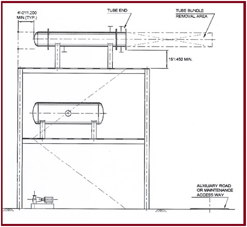
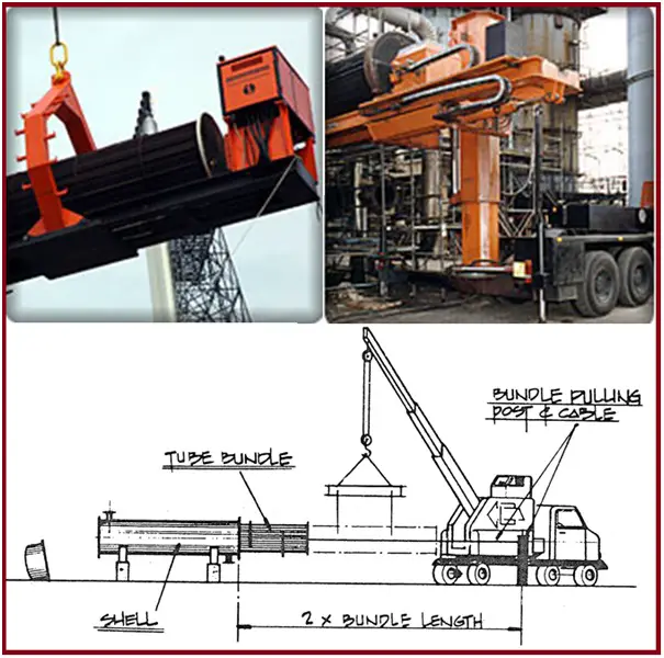
Heat exchanger maintenance
Tube bundle extractors (Fig. 10)
Online Course on Drums/Exchanger Layout & Stress Analysis
To learn more details about the Drums/Exchanger Layout & Stress Analysis method We suggest the following online Course:
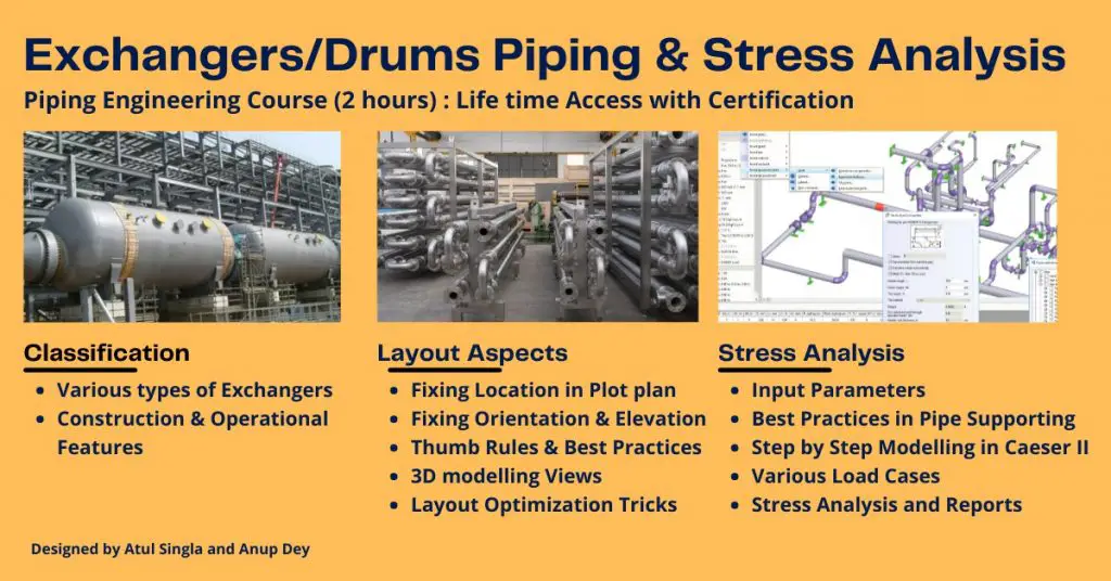
Drums/Exchanger Layout & Stress Analysis: The Complete course covers most of the Layout & Stress Analysis related concepts, step by step modeling in Caeser-II has been defined which every piping engineer should understand.
As you are aware that heat exchangers & drums are an integral part of any plant. This full course is divided into two parts: The Heat exchanger piping layout consists of the following five modules:
- Module 1: Classification of Heat Exchanger: Covers various types of heat exchangers
- Module 2: Constructional and Operating features for all Type exchangers
- Module 3: Layout Aspects to design the layout of
- Shell and Tube exchanger
- Spiral Exchanger
- Plate type Exchanger
- Module 4: Layout Aspects: 3D Pictorial Views
- Module 5: Interesting facts: Optimizing Layout
It will cover all aspects of Piping layouts for Heat exchangers/Drums
The Stress Analysis part will cover the following:
- Various concepts related to Stress Analysis keeping in view the Exchangers/Drums piping have been captured and explained in detail.
- Actual modeling in CAESAR II is done and explained in detail w.r.t. industry practices and various codes & standards.
The major topics that the course covers are provided in Fig. 11 below:
So, simply click here to join the course at an amazing price
Few more resources for You..
Basics of Shell and Tube Heat Exchangers: A brief presentation
An article on Plate Heat Exchanger with Steam
A typical Check List for Reviewing of Shell & Tube Heat Exchanger Drawings
A brief presentation on Air Cooled Heat Exchangers
Basic Considerations for Equipment and Piping Layout of Air Cooled Heat Exchanger Piping
Reboiler Exchanger and System Type Selection
Please provide some overview about stress analysis of heat exchanger connected piping
I think it should be noted, that Fig 3 and 6 are perfect examples how NOT to layout and configure piping around S&T Exchangers.
Wherever this plant is, must be a nightmare for its operations and maintenance staff.
Quite frankly Fig 4,5 & 9 are meaningless. Initial layout studies should be governed by spatial,
ergonomic and safety awareness.
Giving examples of dimensions between equipment and piping can be totally misleading for young designers, as it is very dependent on equipment and piping size and how it is maintained.
Sketches of this type are sometimes 50 years old and really should be scrapped. The size of equipment this days for mega projects really demands a different thought process.
You did a nice work by posting this. I appreciate it and enjoy reading your posts. Keep doing good work.
Thanks for Sharing. Well Explained.
sir do for pressure vessel and storage tank