
Surface Laid Pipelines, as the name suggests, are Pipelines that are laid on the surface of the loose desert sand without any restraints. These unrestrained pipelines, unlike the other unrestrained pipelines, do not have pipe supports to restrain the displacements, hence different approaches and techniques are implemented while analyzing such lines.
The purpose of this article is to illustrate the method to model and analyze surface-laid pipelines using Caesar II and the considerations to be taken care of during the Stress Analysis.
The surface laying of the pipelines is opted for by the client for Cost-benefit. It saves construction costs, maintenance costs, and operational costs largely.
Sites for Surface Laid Pipelines
Surface-laid pipelines have basically opted for the desert sites, where the pipelines are laid in the corridor from the Wellhead up to the Gathering Facility.
Above Ground Surface Laid Pipelines
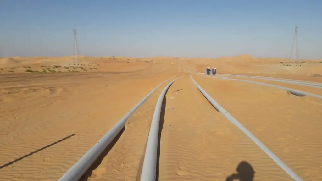
The above-ground surface laid pipelines (Fig. 1) shall be routed in a manner such that no excessive movement occurs on the pipes due to the effects of thermal expansion and/or contraction, internal pressure, and other design internal or external loads. The axial and lateral expansions of above-ground pipelines shall be limited as far as possible. Expansion loops are to be designed to accommodate the axial movements based on CAESAR II stress analysis recommendations for above-ground pipelines.
The above-ground pipeline shall be modeled as “Unrestrained” in the CAESAR II software and should be analyzed using ASME B31.4/B31.8 code calculations.
The unsupported surface laid pipelines shall be installed as unrestrained pipelines & shall follow natural grade elevation
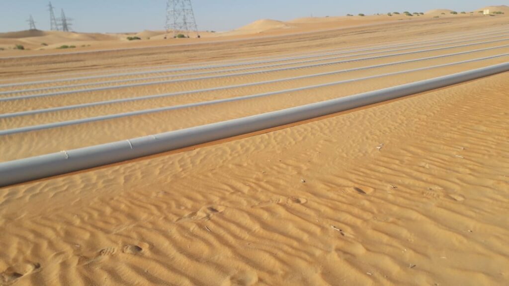
Fig. 1 and Fig. 2 show typical site images explaining how surface-laid pipelines would look.
Considerable Points for Surface Laid Pipelines
The below-mentioned points must be considered while designing Surface Laid Pipelines.
- Wall Thinning of Hot Bends
- Wall Thickness at Road Crossings
- Minimum Radius of Elastic and Cold Field Bends
- Longitudinal Stress, Anchor Force and Free End Expansion Calculation
- Equivalent/Longitudinal Stress Calculation
- Upheaval Buckling
- Stability
1. WALL THINNING OF HOT BENDS:
The process used for bending a hot bend results in some thinning of the pipe wall thickness. An indication of this thinning as a percentage of wall thickness may be determined by the empirical formula stated in BS 8010-2.8 para 2.8.3.9
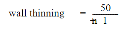
n= is the radius of the inner bends divided by the pipe diameter
2. WALL THICKNESS AT ROAD CROSSINGS:
This calculation determines the minimum wall thickness required at road crossings to withstand normal vehicular loads. The calculation will be based on the method used in API RP 1102.
3. MINIMUM RADIUS OF ELASTIC AND COLD FIELD BENDS:
For liquid lines, the minimum radius of curvature for cold field bends is determined as per the requirement of ASME B31.4 clause 404.2.2 to ensure that the bend will not be overstressed. For gas lines, the minimum radius of curvature for cold field bends is determined as per the requirement of ASME B31.8 table 841.2.3-1 to ensure that the bend will not be overstressed.
4. LONGITUDINAL STRESS, ANCHOR FORCE, AND FREE-END EXPANSION CALCULATION
The aim of this calculation is to determine the longitudinal stress induced in a restrained/unrestrained pipeline as a result of the difference between the installation temperature and the operating pressure and also to calculate the potential anchor force; free end expansion and the virtual anchor length.
ASME B31.8 states that the sum of the expansion stress, longitudinal pressure stress, and applied bending stress must not exceed the 90% specified minimum yield strength of the material. In addition, the longitudinal pressure stress and the applied bending stress must not exceed 75% of the SMYS for the gas pipelines.
5. EQUIVALENT/LONGITUDINAL STRESS CALCULATIONS:
ASME B31.4 uses a term called the Equivalent Tensile Stress to control the combined stresses in the liquid pipelines. The Equivalent Tensile Stress is equal to the sum of the hoop stress and the longitudinal stress imposed on the pipeline. The limit for equivalent tensile stress is set at 90% of SMYS.
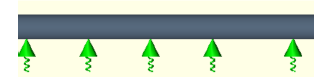
6. UPHEAVAL BUCKLING:
An upheaval buckling calculation may be performed to ensure that the longitudinal forces are not sufficient to force the pipelines out of the ground. The required downforce will be calculated using the method described in OTC 6335 – Design of Submarine Pipelines Against Upheaval Buckling, 1990. The required downforce is dependent on the axial force, which is calculated in the Thermal Expansion Calculation Sheet.
7. STABILITY:
The method used to determine the vertical stability of the pipeline through water courses is to calculate the total weight of the pipeline and compare it with the weight of the external fluid (water) it would displace. In order for the pipeline to be considered stable, the pipeline weight must be 10% greater than the weight of the water displaced
Major points during Stress Analysis
1. During the stress analysis, the analyst shall check the maximum lateral deflections in the system to make sure that the adjacent flow line does not cross each other while in operation considering the spacing between the flowlines mentioned in the specifications.
2. The design shall be adopted to add flexibility by introducing offsets/expansion loops across the route while the lateral deflections of the line shall be within the limits so that the group of lines will not interfere with adjacent lines.
Procedure for modeling in CAESAR II
The methodology for modeling the Surface Laid flowlines are bit tricky and tedious, so proper care has to be taken while modeling the same in the CAESAR II. Since the entire system is without restraint, a slight error might give improper results.
Below is the basic methodology for modeling the Surface laid flowline.
Since the pipeline is surface laid (except at road/track/ other pipelines crossings where it is U/G), a direct method for modeling surface laid lines are not available in CAESAR II (or any other such software) due to the continuous supporting (equivalent to say an infinite number of supports) by natural soil along pipeline routes. The continuous soil supports are therefore taken care of by discrete soil springs and also by selecting such close springs at a distance not more than 5D (i.e 5*219.1 = 1095.5 mm as an example for 8”). Support spacing shall be taken to the nearest round figure (say for 8” as an example at every 1000 mm), using the approximate stiffness in the vertical direction and also using friction value of 0.5 (which varies with the location for such modeling).
This modeling approach has been recommended by COADE (Developer of CAESAR II).
The CAESAR II procedure for finding the soil support stiffness is as given below:
A small stress model of the pipeline shall be created using the actual design data. The small model could be with 25 nodes, with each node spaced at the 5D distance of the line. The model shall be buried using the buried modeler of CAESAR II®, with an assumed soil depth of half the diameter of the pipeline and using the typical soil design parameters. Upon buried conversion, the program inserts soil springs in the converted model of the sample model. The Y2 stiffness shall be read as seen in the converted sample model corresponding to a mid-node number (made free from the end conditions). This is the stiffness to be used in the actual pipeline model as normal rest support.
In case the stress model with 5D support spacing creates a convergence issue due to a large number of soil restraints, the option of removing the friction at several non-convergent supports would lead to inaccuracy of the results. To overcome this issue, a stress model with a larger support spacing (<50D Typical) may be utilized. In this case, the vertical support stiffness to be used shall be determined using the above-mentioned procedure for finding the soil support stiffness with the increased support spacing. In the alternate method, the representative vertical stiffness values as per the Geotechnical report, after consulting the Civil, can be used to simulate the soil springs for surface-laid lines.
To obtain near-realistic results, it is suggested to model with the actual profile of the flowline so as to gain the proper axial and lateral displacements.
The above article gives a broader perspective of general considerations to be taken care of.
Online Video Courses related to Pipeline Engineering
If you wish to explore more about pipeline engineering, you can opt for the following video courses
Hello jimmy,
Do you have something or a guide for Pipeline stress analysis using Autopipe. Kindly respond to my email mathewenude@yahoo.com.
Warm regards,
Mathew Enude .
Nicely explained. Can you provide more sample calculations of above ground piping involving seismic and wind occasional loads?
Thanking you in advance.
An extensive explanation for above ground piping. It would be better if some focus would have been made on Seismic & Wind occasional load. though it was nice reading the article.
Thanks
Kudos for blogging this topic. Do you intend to write more?
Hello engineer,
I would like to know about theoretical explanation for stress analysis for B 31.3 31.4 and 31.8 stress calculation and also how we choose the supports..and trunnion keloggs method how we calculate? Please explain..
Hi Jimmy,
Good to see you here. A question regarding UHB of surface laid lines. Since the pipes are free to move, the phenomena of upheaval buckling is not practically possible. Instead, lateral buckling shall apply.
Looking forward for your more articles.
Hi, can we directly make soil model rather than finding stiffness and model each rest support with stiffness?
We can also calculate the stiffness, though it would be over conservative.
Hi jimmy.. Excellent article.
However, i have one doubt. I hope you can clear it.
I have one surface laid pipeline (6″ sch-120, X-52 grade), where at bend (20°) I am experiencing very high lateral movement in the range of 1500 mm even though the distance between bend point and anchor on both sides is less than 200mm.
Temperature is also not much (120°C)
What is the straight length of the pipe.
Nice article Jimmy
Hi,
Thanks for sharing this article.
Are there any recommendations you have for sand removal that accumulates on the top of surface laid flowlines over time? Are there any vacuum or sweeping techniques/machines which have been used for clearing and maintenance activities?
Thanks,
Andy