
A piping system consists of many different components such as bends, elbows, reducers, tees, valves, and flanges. However, in the pipe stress analysis, these various components are idealized into two types of elements:
- The first ones are the straight pipe beam element and
- others are the curved pipe beam element
A piping system depends mainly on its bending flexure to absorb thermal expansion and other displacement loads. When a straight pipe is subject to bending, it behaves like any straight beam i.e. its cross-section remains circular and the maximum stress occurs at the extreme outer fiber. However, under a bending moment, the piping component behaves differently from that of a solid curved beam. When subject to a bending moment, the circular cross-section of the bend becomes oval.
To accommodate this behavior of piping component which is different from a straight pipe, SIF and flexibility factors are used.
ASME code requires the use of stress intensification factors (SIFs or i-factors) and flexibility factors (k-factors) when checking the adequacy of components and joints in piping subject to various loads, including cyclic loads, that may produce fatigue failures.
In this article, we will explore the terms Stress Intensity Factor, Flexibility Factor, ASME B31J, etc. in more detail. At the end of the article registration link for a webinar recording on the same subject is provided. Kindly register and listen to the same for more insights on the subject from AutoPIPE expert Mr. Manoj Kale.
What is the Flexibility Factor?
For branch connections and reducers, the Flexibility Factor is a ratio of rotation of one end of a zero- or negligible-length element with respect to the opposite end of the same element when equal and opposite moments are applied at each end;
For bends, the Flexibility Factor is a factor based on an effective length of matching pipe that increases the element flexibility to simulate the effect of bend ovalization that applies over the entire arc length of the bend.
What is the Stress Intensity Factor (SIF)
Stress Intensity factor or SIF is a piping component fatigue strength factor that is the ratio of the elastically calculated nominal stress in a matching pipe that causes a through-wall crack to appear in a given number of cycles in a straight pipe butt weld to the elastically calculated nominal stress in the matching pipe used with the component that produces a through-wall crack in the same number of cycles in the component or attached pipe.
SIF is intended to be used for evaluating self-limiting stresses, derived from low-cycle fatigue tests.
Each code has tables that list and explain the flexibility factors and SIFs for most of the common components used in a piping system.
Although flexibility factors, used to calculate the piping forces and moments, are all similar, SIFs differ slightly between the codes.
To show the function of these tables, we use ASME B31.3 tables D300 as an example. The B31.3 table is more complicated than the others. It shows in-plane and out-plane categories of SIFs for each type of component.
The purpose is to apply different stress intensifications on the different orientations of the moment.
These tables are used as follows. For each component, we first have to calculate the flexibility characteristic, h. From this flexibility characteristic, the flexibility factor and SIFs are calculated.
It is clear from the table that for all the different components only the flexibility characteristics are calculated differently. The flexibility factor and SIFs are calculated more or less the same way for all components.
ASME B31.1 provides only one stress intensification for each component which is greater of in-plane and out-plane values. Hence it is not necessary to distinguish in-plane moment or out-plane moment for B31.1 calculations
What is the Pressure Stiffening of Bends?
In large-diameter, thin-wall elbows and bends, pressure can significantly affect the magnitudes of the flexibility factor.
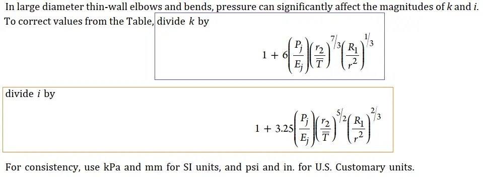
This correction in Stress intensification factor and flexibility factors can be considered by modification factors adopted from ASME codes as shown above in Fig. 1
What is ASME B31J?
ASME B 31J provides a standard approach for the development of SIFs, k-factors, and sustained stress multipliers for piping components and joints of all types, including standard, nonstandard, and proprietary fittings
The aim of using ASME B31J is to improve upon existing SIF and k-factors to get experimentally evaluated more accurate values to get realistic results.
The B31J 2008 edition provided a series of testing procedures to determine the SIFs. The 2015 edition brings experimentally-evaluated definitions based on component geometry, whereas the 2017 edition brings updates on the same.
All SIF and flexibility factor values are evaluated by calculations based on empirical, experimental, and FEA data from the observation of testing procedures.
B31.1 & B31.3 provide guidelines for to use of B31J. ASME B31J evaluation methods can be used in conjunction with ASME B31.1 and ASME B31.3 with 2012 and later editions. AMSE B31J can be used for metallic piping to calculate SIF and k-factors.
This code provides a standard approach for the development of SIFs, k-factors, and sustained stress multipliers for piping components and joints of all types, including standard, nonstandard, and proprietary fittings.
These SIF and k factors in ASME B31J are defined by performing multiple tests on pipe specimens by manufacturers or piping component users
Typical tests conducted as part of a piping component evaluation include,
- burst test
- SIF test
- k-factor test
- sustained load test
Nonmandatory Appendix A provides the standard method to develop stress intensification factors. Nonmandatory Appendix B provides the standard method to develop branch connection flexibility factors. Nonmandatory Appendix C demonstrates how the new branch connection k-factors should be used in the elastic analysis of piping systems, and Nonmandatory Appendix D provides a standard method to develop sustained stress factors.
Stress intensification and flexibility factors for most applications currently available metallic piping components were developed using the test procedures and numerical methods in this Standard and those are included in Table 1-1. These values should be used with the section modulus of the matching pipe
ASME B31.3 SIF vs AMSE B31J SIF
For each component, AMSE B31J provides 3 sets of equations or we can say that unique equations in each of 3 different directions for SIFs and flexibility i.e. in-plane, out-of-the-plane, and torsional.
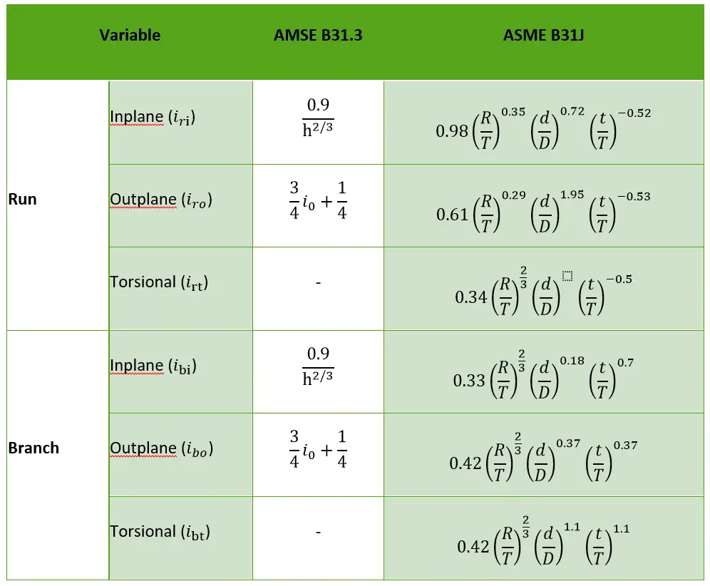
We can see the same in Fig. 2 for Welding Tee.
ASME B31.3 has the same equation for the branch and run leg of the welding tee in in-plane and out-of-plane direction SIF. So there are only 2 equations. Whereas ASME B31J provides unique equations in each direction for both branch and run of the tee. When the design Code requires the use of a single stress intensification factor, the largest of the directional stress intensification factors shall be used.

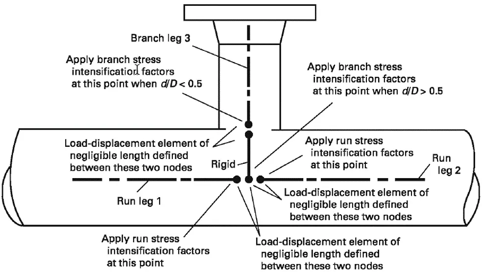
The Branch Stress intensification factor applied is dependent or independent of the image (Fig. 3) shown here at the bottom and the location of stress is dependent on the relation of geometry between the branch and the header.
Torsional SIF
ASME B31.3 has torsional SIF considerations in sustained, expansion, and occasional stress for some time, but previously it was always using a value of 1. The introduction of B31J will support torsional SIF values other than 1 for AMSE B31.3 stress calculations.
So if you’re using B31.3 without B31J you will be able to enter user-defined torsional SIF values.
Flexibility factors as per AMSE B31J and ASME B31.3
Firstly, only Tee components are affected by the updated flexibility factors as per B31J whereas flexibility factors are the same for other components. Tee flexibility factors themselves were evaluated using static analysis for each Tee in the model. During our main static analysis system processor, we actually re-structure the stiffness matrices. The flexibility factors themselves are based on Tee geometry and joint definitions.
As the same with SIF calculations, branch flexibility values are now independent of the header. Here’s an example of the flexibility factors for both the run and the branch leg (Fig. 4) of a welding Tee as ASME 16.9.
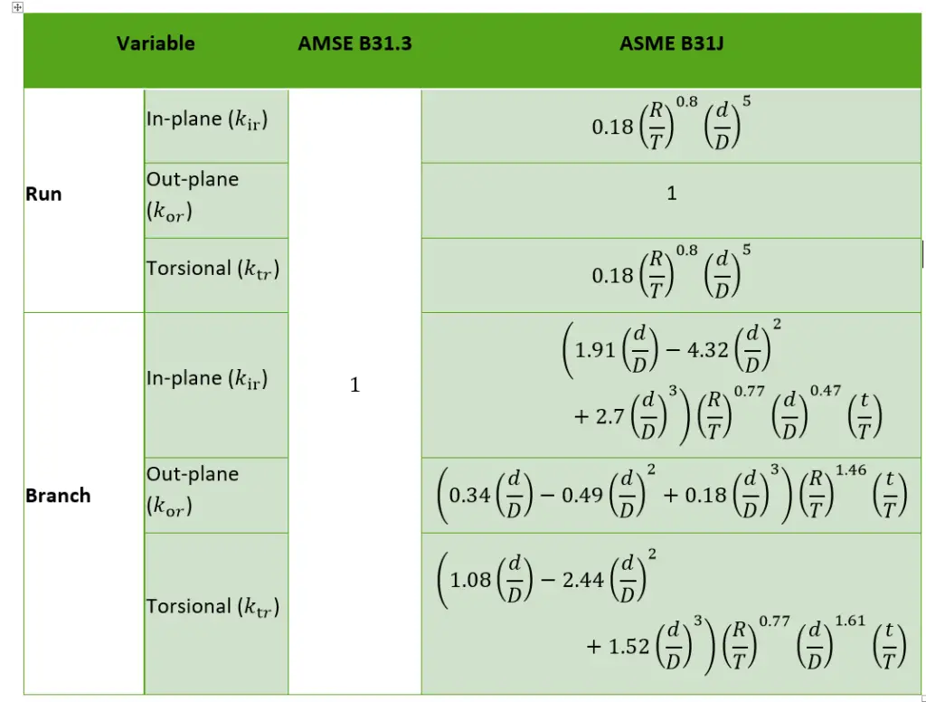
So, each tee will produce six independent flexibility factors one for each direction, i.e. in-plane, out-plane, and torsional.
So B31.3 is currently restricting the flexibility factors to a very small value which makes the piping tee more rigid and what this code aims to do is to provide a more detailed flexibility analysis by using accurate flexibility factors as per tee geometry.
SIF and Flexibility Factor Webinar using AutoPIPE
Please listen to the following recorded webinar for more detailed insight on SIF, Flexibility factor, and ASME B31J which was conducted on Wednesday, May 27, 2020, at 10:00 AM IST. Click here to register and view the recording of the SIF webinar.
Summary
- ASME B31J provides more realistic and more accurate SIF and flexibility factors and hence provides more realistic code stresses than existing ASME B31.1 and B31.3 codes.
- As I already explained additional geometric restrictions should be reviewed by the designer prior to accepting stress results. Those can be seen in model consistency checks and code themselves. Needs to review them before actually reporting your results.
- ASME B31J can be applied to ASME B31.1 and B31.3, 2012, and later edition models. This is sort of an initial step and later it will be expanded further.
- And finally in AutoPIPE AMSE B31J SIF and flexibility calculations are enabled with simple clicks. Then you just have to provide some additional geometry information, then run an analysis, and review the results.
- Flexibilities used for piping and nozzle connections by most piping and pressure vessel designers or stress analysts are based on old technology. These flexibilities have a significant impact on displacements, forces, and stresses, often skewing results from reality.
- Using B31J one can find many opportunities to reduce design time, construction costs, analysis time, and lifecycle maintenance costs.
Few more related articles to increase your knowledge.
Piping Elbow or Bend SIF (Stress Intensification Factor)
Importance & Impact of Stress Intensification Factor (SIF): A Presentation
How to use ASME B31J-2017 and FEM for SIF and k-factors for Stress Analysis
ASME B 31J & B 31J Essentials: Why these are useful in Piping Stress Analysis?
Applicability of Caesar II for stress analysis of lines having D/t ratio more than 100
11 most important questions & answers from ASME B 31.3 which a Piping stress engineer must know.
Where is Fig.1?
Hi Anup,
Interesting piece of informations because I have had a very long discussion with a couple of colleagues regarding how to define SIF at different points in/on a branch –> problem solved 🙂
Frank
Hi Anup,
Please tell me.
In the ASME B31J standard, there are two stress indices for tees: one for the main pipe (run pipe) and one for the branch pipe. When d/D>0.5, as shown in Fig.C-2-7, two stresses (main pipe stress and branch pipe stress) are evaluated at the intersection of the main pipe. Does this mean that the evaluation is the same as in the ASME Section Ⅲ NB-3600 standard, that is, the two stresses B2bMb/Zb and B2rMr/Zr due to stress indices B2b and B2r are summed up?
Thank you.
//sadao
what if the elbow SIF value is 1.65, is this elbow is safe and withstand the loads.