
Bourdon Effect on Pipelines
Bourdon Effect is associated with the pressure elongation of the piping and pipeline systems. In piping and pipeline systems, elbows or bends are frequently used for changing the direction of the pipe. The behavior of elbows and bends subjected to internal pressure is quite different as compared to a straight pipe. Due to the difference between the intrados and extrados surface area of bends, the pipe starts to straighten out by the unbalanced force arising from the internal pressure. This tendency of pipe bends to open up under internal pressure force is terms as the Bourdon effect. Also, the unbalanced pressure thrust force causes the straight pipe to elongate.
Traditionally, the impact of the bourdon effect is not considered for steel piping systems as the effect is negligible. However, with an increase in pressure and pipe length, specifically for long pipeline systems this effect is considerable and must be used in the analysis to avoid unanticipated deformations and high stresses at elbows. At the same time for analyzing plastic piping systems like PE, HDPE, GRE, FRP, and GRP systems, the bourdon effect must be considered.
Background of Bourdon effect in PASS/START-PROF
PASS/START-PROF always takes into account the Bourdon effect. By default, the option is made on and the users can’t turn it off. We insist on it because we had a lot of situations when users forgot to take this effect into account where it was really needed: for high-pressure piping systems and pipelines, HDPE, FRP, GRP, and GRE piping. This rule is needed for safety and provides protection from human mistakes.
But this decision produces a lot of questions from our PASS/START-PROF software users who think that the pipe support load is “incorrect” from their point of view, or thinks that equilibrium conditions are “not satisfied” between the anchor load and the internal force in the connected pipe.
After discussions with our customers, We realized that a lot of experienced engineers confuse about the understanding of the pressure thrust effect and how it should be used for support and nozzle load calculation, buckling calculation, flange leakage calculation, and stress calculation. A lot of people think that pressure doesn’t produce any deformations and loads at all.
I have to explain it every time, again and again to each customer within software technical support.
Finally, I decided to make a poll on the social media platform LinkedIn with the following simple question (Fig. 1).
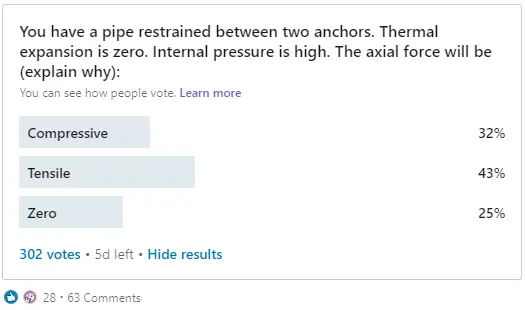
The result was stunning. The distribution of votes was almost even. So I decided to write this article to help piping engineers understand this phenomenon better. And also explain how PASS/START-PROF software deal with it.
The Pressure Effect Problem Description
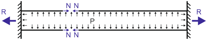
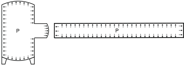
The problem from the above poll (Fig. 1) can be illustrated with the following picture:
In the beginning, please read the first part of this article about a restrained, unrestrained, and partially restrained pipe. I will show here (Fig. 3) only the final table with the equations.
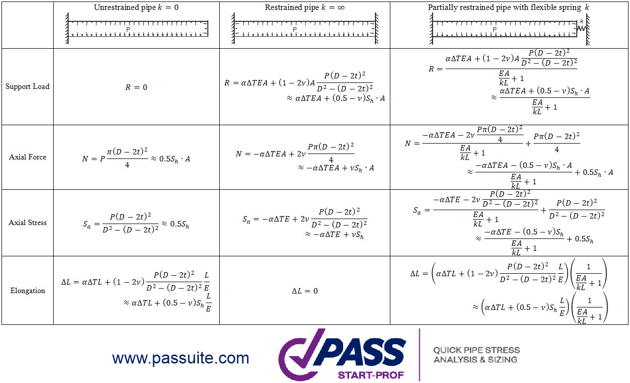
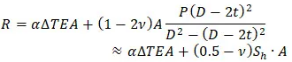
The pipe axial force equation is following:
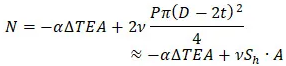
If the thermal expansion is zero, then the internal force from “pure” pressure will be positive, i.e. tensile. So the correct answer in the above poll (Fig. 1) is “Tensile”.
In the literature the force “N” is called the “True Axial Force”, and the force “R” is called the “Effective Axial Force”. I didn’t know that before, until one day while I had a conversation with my customer got my attention to this fact. That’s why I call these forces just “Axial Force, N” and “Support Load, R”.
“True” and “Effective” Axial Force
The support load equation “R” from the table above is called in the literature an “Effective Axial Force”. The axial force “N” is called the “True Axial Force”.
For the example model from the poll the “Effective Axial Force” can be interpreted as “compressive”, because it produces the loads that push the anchors apart:
But this is just a fictitious definition. The real axial force “N” in the pipe wall will be tensile.
The “True Axial Force” (Axial Force “N” in the table above) is used for:
- Axial pipe stress calculation.
- Local pipe wall buckling analysis.
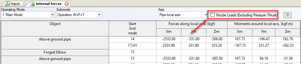
- Pipe element internal forces. The checkbox “Nozzle Loads” should be unchecked as shown below
The “Effective Axial Force” (Support Load “R” in the table above) is used for:
- Loads on the support calculation.
- Loads on Pressure Vessel and Tank Nozzles, Rotating Equipment Loads, etc.
- Flange Leakage Check.
- Pipeline upheaval buckling calculation.
- Pipeline global buckling (Euler buckling) calculation.
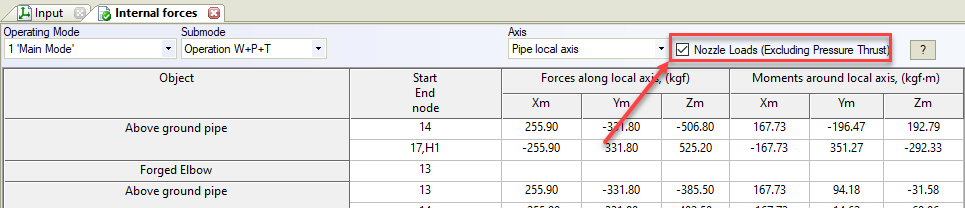
- Pipe element internal forces. The checkbox “Nozzle Loads” should be checked
Why the “Effective Axial Force R” should be used to calculate the nozzle loads, flange check, and global buckling instead of the “True Axial Force N”?
If the left end of the pipe in the picture below is connected to the pressure vessel nozzle or rotary equipment, then the “true” axial force in the equipment nozzle will be N (see table above). But when equipment manufacturers calculate allowable loads using finite element software like PASS/NOZZLE-FEM, they assume that the nozzle has the end cap and the vessel is under pressure. This means that axial stress caused by pressure thrust is already taken into account when nozzle allowable loads were calculated and should not be considered twice.
Hence we must exclude the pressure thrust load from the True Axial Force and use this value to compare with the nozzle allowable loads. This means that we must use the Effective Axial Force “R” for equipment nozzle checks. For example, if we connect a pipe with the end cap to the nozzle, the true True Axial Force in the nozzle wall will be
But we should exclude the pressure thrust component from this force i.e. use the Effective Axial Force that equals zero. Just imagine that the nozzle and the pipe both have the end caps like in the picture above. Therefore the nozzle load will be zero.
The same explanation can be offered for the flange leakage check. If you look at the equivalent pressure method equation, you will see, that the internal pressure is already taken into account and we should apply only additional loads, caused by thermal expansion and other influences, but not by the pressure of the thrust.
But why we should use the “Effective Axial Force” for global buckling and for upheaval buckling calculation, but at the same time use the “True Axial Force” for local pipe wall buckling? This phenomenon is a little bit harder to explain. I will try to do it using simple examples.
To calculate the longitudinal buckling we need to consider the deflected pipe shape, not the initial (installation) shape. To explain this effect, let’s look at this simple model, consisting of the two pipes
- (a) The “cap pressure” forces acting on the pipe ends P·A as a result of summing the vectors produce the force “S” that tends to push the pipe in the lateral direction.
- (b) If we represent the pipe as a polygonal chain, then at each turn of the pipe we will have a lateral force “S” trying to push the pipe away.
- (c) And finally, if we will represent the pipe as the infinite number of polygons, we will have a uniform lateral load “S” that leads to pipeline global buckling.
I will pass the derivation of equations process, you can find it in the literature and just say the final conclusion is that the effective axial force “R” should be compared with the critical axial force value, not the true axial force “N”. For elastic buckling, without the soil resistance and thermal expansion Euler’s equation will be:
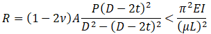
The additional “cap pressure” force generates the distributed load “S”.
This phenomenon can be explained by the fact that in the deflected form, the outer pipe wall length is longer than the internal wall length, hence the total pressure force on the outer surface is greater by the “S” value.
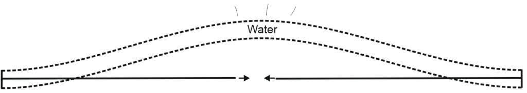
Also, the next analogy helps to understand this phenomenon. Imagine the restrained pipe under the pressure just like the reinforced concrete beam. The pipe is playing the role of the reinforcing bar (stretched) and the pipe content (water) buckling happens just like the compressed rod (see the picture below).
The global buckling is checked using START-Elements procedure.
I hope this article will help engineers to understand the Bourdon effect better and critically review the results obtained from the various pipe stress analysis software.
Here is the video that demonstrates how the pipe buckling due to internal pressure caused the Deepwater Horizon Blowout, which resulted in the deaths of 11 workers and caused a massive, ongoing oil spill into the Gulf of Mexico.
To listen to the author about the above article and learn follow the following video post:
Very Important & Valuable for pipe line maintinence.
Thank you
this is very interesting article and i am reading again and again and again.
I have a question.
Near Fig 4, above and below, Pie element internal forces are mentioned both for true axial force and for effective axial force.
Is that right? I guess either should be deleted.
It is not mistake. In START-PROF software you can see both true and effective axial internal forces. If the checkbox “Nozzle Loads (Excluding Pressure Thrust)” is checked you will see effective axial force, if not checked you will receive true axial force.
Hello,
I come back again and sorry for late.
2 questions.
1) in regards to previous questions, I understand we can choose either to include or to exclude the effect of pressure in element force calculation in PASS/START-PROF. My question was…when we need to see calculate element force.
2) I understood pressure effect should be excluded and Effective Axial force should be used when nozzle load check and flange check because it is already taken into account at allowable values from vendor. But I don’t understand why it is true for load for support calculation. Could you elaborate a little bit more or any references?
1) We need to see the internal force to use it in buckling analysis, for example
2) Because if we have an Anchor or any other type of support in the end node of the pipe, we assume the pipe has a cap also. If it is not have a cap, then we need to consider the thrust force like in the relief valve
Thank you for the important article.
This article is so relevant for me as I’m working now on GRP pipes analysis.
I got a little confused with the end of the article regarding the nozzle check.
I modeled a pump discharge nozzle as an anchor. The anchor is subjected to high axial load (thrust force) due to the internal pressure mainly because of the large pipe dia. 60″.
I sent the above load among the other loads to the pump manufacturer for his examination.
Now my question is:
Am I right in sending the above load to the mfr. or should I have omitted it from the total loads?
Thanks,
Thanks for your experience sharing!
As you mentioned, bourdon effect must be considered for PE, HDPE and RTRP pipe stress analysis. I am curious about how to do stress calculation for PE or HDPE pipe, could you please show a light on this topic?
Very appreciate for your reply!
Hello Alex,
I come back 2 years later from my first question.
While I review the article written by Peng, titled “Stress Analysis Methods for Underground Pipe Lines Part 1 – Basic Calculations”, I found his statement is directly opposite to what you said.
From Peng’s article, see Eq. (3). It is longitudinal stress for fully restrained pipe and I understood it is interchangeable with axial stress here. If I multiply the crosssection area, A, it becomes an axial force identical to N in this article.
While you obviously stated the force acting in the pipe from the poll is tensile, Peng said it is compressive. This is his statement, “The net longitudinal stress becomes compressive for a moderate increase of T2”. Additionally, 3. Compressive longitudinal stress at the fully restrained portion at Sample calculations shows a negative value, which means compressive.
Could clarify why Peng and your statement are different?
In the poll, the thermal expansion is zero. Therefore longitudinal stress from internal pressure will be Sa=+v*Sh (Tensile)
(-) means compressive stress, (+) means tensile
If thermal expansion is positive and non zero then yes, the longitudinal stress may become compressive. But in the poll I asked about stress from the pure pressure. Without thermal expansion
Thank you. I forgot the fact that thermal stress is zero. All cleared!!