What is a material selection diagram?
A material selection diagram often called MSD in engineering terminology is basically an engineering drawing that shows the basic scheme of a process along with the information for material selection & specification of all the equipment, and lines associated with the process as well as utilities & offsite.
What is the purpose of the material selection diagram?
As we know, in a project, the cost of the materials contributes a major part to the overall project cost. So selection of proper material is a very important parameter. Besides, the important parameter of a project like the overall design, stability, and sustainability also depends on material selection.
As MSD summarizes the related information that is required for material selection of the equipment & piping in process industries so MSD is a necessary document for developing piping material specification (PMS). The piping material specification is an important document by material engineers and it is used for assigning line class/ specification to each line on the P&IDs.
How to develop a material selection diagram?
In the simplest form, an MSD is a drawing that consists of a marked-up or overlaid version of a PFD (process flow diagram). So to develop an MSD you need to have the following documents,
- a) Basic Engineering Design Data (BEDD)
- b) Simplified Process Flow Diagram (PFD),
- c) Material selection information developed by the process team,
- d) PFD marked up with proper operating pressure, temperature, design temperature, and pressure.
The content, format, use, and updating philosophy of a material selection diagram must be in agreement with the client and contractor/fabricator/licensor in the preliminary phase of the project.
Besides the above, all main documents and some other suitable standards like API, NACE, corrosion curves, and company standards shall be used as necessary documents for developing MSD
Who develops the material selection diagram?
In general, MSD is prepared by a material engineer or metallurgist in collaboration process engineer. The material engineer responsible for developing MSD must be familiar with the corrosion mechanism of the material, particularly the type of unit being designed.
Information to be shown on MSD
- Material of construction used for the equipment & its component, piping network (as per material legend), normally recognized by name or by tag. (See Table: 1),
- Chemical injection, corrosion inhibition points,
- Corrosion allowances,
- Corrosion-resistance cladding of alloy with minimum thickness & side of the components,
- Linings/coating for specific internal corrosion consideration,
- Prefabricated equipment as “Manufacturer’s Standard”,
- A special section of materials, prevention of corrosion, testing requirements in the form of notes (e.g. thermal stabilization, stress-relief [SR] requirements, maximum hardness requirements, velocity limits, etc. The equipment components whose material of construction to be shown are as below,
| TYPE OF EQUIPMENT OR PIPING | COMPONENTS | Mandatory/Optional (M/O) |
| Heat Exchanger (Plate and Frame) | Plates Frame Gaskets | M O O |
| Heat Exchanger (Shell and Tube) | Shell Channels Baffles/Cages Tubes Tube sheet | M M O M M |
| Tank | Shell (includes fixed roof and bottom) Floating roof Linings Seals | M O M O |
| Towers | Shell Trays/ Packing Distributors | M M O |
| Centrifugal Pumps | API material Class(if applicable) Casing Impeller | O O O |
| Drums | Shell Boot (if present) Internals | M M O |
| Piping | Pipe Control Valve Valve trim | M O O |
| Reactors | Shell Internals | M O |
| Heater | Radiant tubes Convection tubes Hangers | M M O |
| Air Cooler | Headers Tubes Plugs (if different) | M M O |
MOC for supplementary components like special gaskets, seals, etc should be identified on MSD. Additional components like bolting, impingement plates, and vessel trims may be included based on factors such as whether the materials are covered in other sites, projects, or company work practices.
Material Designations
Materials should be designated by standard formats e.g. CS or UNS (unified numbering system), 316 SS. Another specification is ASTM (e.g. A516, A351), DIN (Deutsches Institut fur Normung), etc. Generally, using specific material specifications (e.g., ASTM, ASME, and DIN) is acceptable in agreement with the client and contractor. There is a legend that should be used in each MSD. A typical example of a legend is tabulated in Table: 2.
| MSD | UNS Designation | Full Designation |
| CI | Cast iron | |
| DI | Ductile iron | |
| CS | K02504, K02401, K03006 | Carbon steel |
| LTCS | Low-temperature Carbon steel | |
| 1-1/4 Cr | K11562, K11756 | 1 ¼ Cr- ½ Mo |
| 2-1/4 Cr | K21590 | 2 ¼ Cr-1 Mo |
| 5 Cr | K21590 | 5 Cr- ½ Mo |
| 9 Cr | K81590 | 9 Cr-1 Mo |
| 12 Cr | S40500 (405 SS), S41000 (410 SS), or S41008 (410S SS | 12-13 Cr steel |
| 304L | S30403 | 304L SS |
| 316L | S31603 | 316L SS |
| 321 | S32100 | 321 SS |
| 347 | S34700 | 347 SS |
| 310 | S31000 | 310 SS |
| 2205 | S32205/S31803 | 22% Cr Duplex SS |
| Alloy 20 | N08020 | Alloy 20 |
| 6% Mo | S31254, N08367, N08926 | Super austenitic SS with 6% Mo |
| 800 | N08800 (alloy 800), N08810 (alloy 800H), or N08811 (800HT) | Alloy 800 |
| 825 | N08825 | Alloy 825 |
| 625 | N06625 | Alloy 625 |
| 276 | N10276 | Alloy 276 |
| 400 | N04400 | Alloy 400 |
| Adm | C44300, C44400, C44500 | Admiralty brass |
| NRB | C46400, C46500, C46700 | Naval rolled brass |
| 70/30 | C71500 | 70/30 Cu-Ni |
| 90/10 | C70600 | 90/10 Cu-Ni |
| Ti-2 | R50400 | Titanium grade 2 |
| Ti-12 | R53400 | Titanium grade 12 |
Format of Notes & Contents
General Notes: These are the notes which are applicable to the whole process unit & must be labeled with a discrete letter on all MSDs. These should be repeated in a similar order using the same letter on all MSDs.
Specific Notes: These notes are specific to the specific equipment, piping component, or location on the MSD. This note should be identified with a discrete identifying letter and generally follow the general notes on the corresponding MSD page (if MSD is more than one page).
The below table (Table: 3) is the list of commonly used nomenclature that is generally used in the process industry,
| Nomenclature | Actual Meaning |
| B | Baffles |
| C | Casing |
| CA | Corrosion allowance |
| CH | Channel |
| H | Header |
| IMP | Impeller |
| INJ | Injection point (e.g. wash water, chemical) |
| INT | Internals |
| PWHT | Post-weld heat treatment for service or material. (Design code requirements for PWHT based on thickness must also be met, but are not typically identified on the MSD.) |
| SH | Shell |
| SR | Stress relief |
| T | Tubes |
| TS | Tube sheets |
Requirements of special materials shall be shown in MSD, normally in the specific note region. The typical example of special requirements is as follows,
- -Alloy 20 or alloy 825 drains in SS reactor,
- -Higher content (>2.5%) of molybdenum for type 316L SS in cold, used in seawater, naphthenic acid service,
- -Maximum limit of strength on CS used in LPG sphere,
- -Welds & thermal stabilization of base materials for type 321 SS or 347 SS that is operated more than 427ᵒC,
- -Seals & gaskets used for MTBE (methyl tert-butyl ether) service, etc.
Corrosion Allowance
Corrosion allowance is a driving parameter for material selection for construction, especially for the equipment which is operated at high pressure. So defining the CA plays a very important role. A certain acceptable CA shall be shown on the MSD for every component excluding pump casing or when the client defines only a minimum CA for a specific material that must be written as a general note.
Process data to be shown on MSD
The process data used for materials selection must be indicated on the MSD. These process data may vary unit-wise. Examples of some typical process data (as applicable), including contaminants & corrosive agents which have the potential ability to affect materials selection, include:
- – Operating temperature
- – Operating pressure;
- – Hydrogen partial pressure
- – MDMT
- – H2S, CO2 concentration, or partial pressures
- – Sulfur, Free water, Ammonia, Chloride concentrations
- – Water dew point
- – Phase (Liquid, vapor, or mixed phase)
- – Amine type, strength, and acid gas loading
- – Total acid number (TAN) or neutralization number
- – pH
- – Critical corrosion velocity limits
- – Short-term operating conditions that could affect materials selection.
The source of the process data e.g. pH, hydrogen partial pressure, H2S concentration, etc, may be found in heat & mass balance. These data can be represented in a separate sheet. If so, the page number & revision of information shall be shown in MSD.
Guideline on completing Material Selection Diagram
MOC & CA should be decided on the basis of predicted corrosion rate or material degradation rate under influence of all process variables e.g. stream composition, velocity, temperature & pressure, and the design life of the specified component.
- -Most cases the maximum normal operating condition is used to decide the materials. Design temperatures & pressures are not usually used to calculate predicted corrosion & degradation mechanism.
- -In some environments, huge corrosion or degradation of materials can occur when normal operating condition is exceeded. So the effect of short-term conditions on MOC needs to be considered. Examples are Alternate operations (presulfiding, catalyst regeneration), No flow (power failure, steam-out, cleaning, etc), Start-up & shut down, Upsets & emergency conditions, start of run (SOR) & end of run (EOR) conditions.
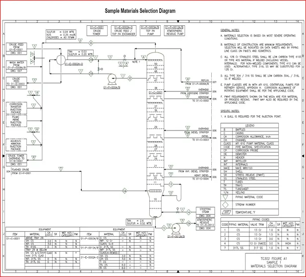
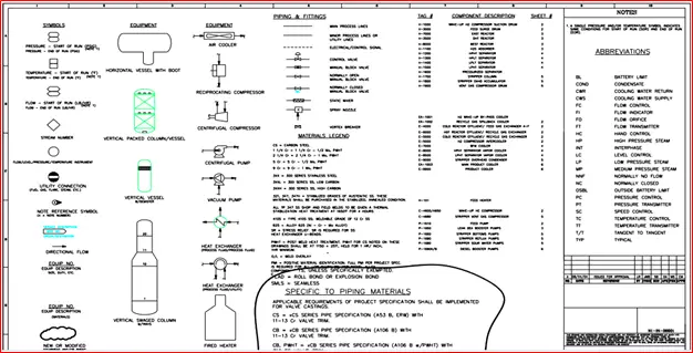
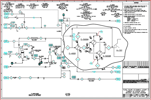
Material Selection Diagram Sample
The below figures (Fig. 1, Fig. 2, and Fig. 3) show a sample of the material selection diagram examples: