
In the Piping and Pipeline Engineering field, Miter Bend plays an important role because standard Elbows are not easily available and economical for larger pipe sizes. The site Engineer or the Fabrication supervisor is responsible for the perfect delivery of the joints made for the miter bend.
This article will provide detailed calculation procedures for finding out the required dimensions, angles of cut, and weight of the pipe.
What is a Miter Bend?
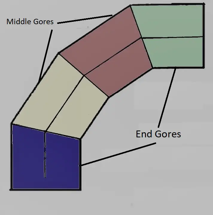
A Miter Bend or Miter Elbow is prepared by mitering (angle cutting) and welding pipe ends of the cut pieces, usually at 45° and 90° to form a corner. There are two types of miter bend, one non-perpendicular bend & another is 3-D bend. Miter Elbow/Bend is made from miter-cut pieces of pipe. The Miter pieces also called gores, There are two end gores and two middle gores in a 4-piece Miter bend.
Miter Bend as per ASME B31.3
ASME B31.3 defined miter bend as follows:
A miter bend is a piping or pipeline bend where two or more straight pipe sections are joined in a plane bisecting the angle of the junction that produces a directional change of more than 3 degrees. If the angular offset is 3 degrees or less, the design consideration as per miter bend is not required.
The pressure design of mitered bends is covered in clause 304.2 of ASME B31.3.
Limitations of Miter Bend Applications as per ASME B31.3
- For normal fluid service, the miter bend can be used but the maximum allowable pressure limits provided in Equations 4a, 4b, and 4C must have to be satisfied.
- For category D fluid service, a mitered bend can be used when the single joint makes a direction change greater than 45 degrees.
- For severe cyclic conditions, miter bend can only be used when the direction change angle is 22.5 degrees or less.
- For high-pressure piping systems, the use of miter bends is not permitted.
Standards Associated with Miter Bend
- AWWS (American Water Work Association): For sizing and the number of cuts/miter.
- ASME B16.9: For end preparation of the miters
- ASME B31.3: For pressure design
Note: According to ASME B31.3, the number of miters is restricted to a maximum of 5.
Features of Miter Bends
- Miter bends are not standard pipe fittings but fabricated piping components.
- It is also called a fabricated bend or mitered elbow.
- Highly skilled welders and fitters are required for perfect miter bend preparation.
- Used mainly in general services (category “D” fluid).
- If used in process lines then above 14” pipe size.
- Used above 6” for utility lines.
- Miter bend can be fabricated with 2, 3, 4, & 5 miters.
- The number of cuts will be a maximum of 5.
- The miter thickness is usually different from the parent pipe thickness.
- The radius of miter bends can be 1D, 1.5D, 2D, 3D, 5D, 10D, or Customized per the application requirement.
Note:
1. The number of miters will be decided according to the pressure and temperature of the line.
2. Application size range can vary from company to company.
Mitered bends are considered in piping applications when standard elbows are not easily available in the required schedule and the cost becomes too high. These are usually the last choice for every project.
Limitations of Miter Bend
There are certain limitations of miter bends as listed below:
- Poor strength as the number of weld joints is higher.
- Higher pressure drop.
- Higher turbulence.
- Used mostly for low-pressure piping systems only.
- Higher risk of corrosion because of more numbers of weld joints.
- Less strength.
- Not suitable for pigging.
- High-skilled manpower is required.
- Not economical for lower line sizes.
- It is not suitable for pigging operations.
Advantages of Miter Bend
Miter elbows provide certain benefits like
- Low cost.
- No thinning required
- It can be made at the site or in the workshop.
Inputs Required for Miter Bend Calculation
| Pipe/Line Size | Schedule Number | Material of Construction or Material Type | Bend Angle | Number of Cut | Radius of Bend |
|---|---|---|---|---|---|
| 8″ | SCH 120 | CS (Carbon Steel) | 90 | 3 | 2.5 D |
Note: D = Pipe/Line size
Steps for Calculation
Step-1: Write down the available data(refer to Table No. 1)
We have,
D = 8”, OD (Outer Diameter) of pipe = 219 mm
Schedule- SCH120
Material- CS (Carbon Steel)
Bend Angle = 90°
No. of cuts = 4
R = 2.5 D = 2.5*8*25.4 = 508 mm
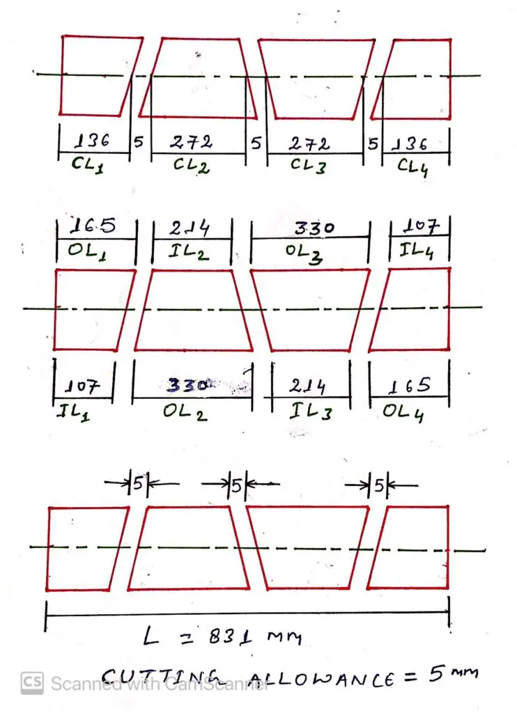
Step-2: As per the number of cuts, Sketch the drawing as below (refer to Fig. 2)
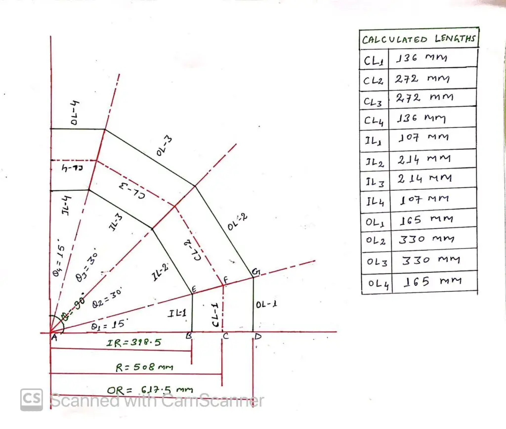
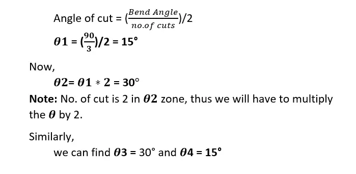
Step-3: Find the Angle of the Cut (refer to Fig. 2 for all the steps)
We know,
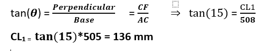
Step-4: Find the Center Line Length (CL1) of the First Miter
We know from Pythagoras’s formula,
Important Note:
- The first and last miter always will be of the same length at each point.
- Except for the last miter, all the miter’s length will be double of the first miter at every point.
Therefore,
CL2 = CL1 * 2 = 272 mm
CL3 = CL1 * 2 = 272 mm
CL4 = CL1 = 136 mm
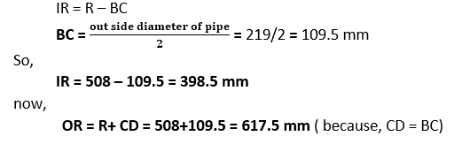
Step-5: Calculate the Inside and Outside Radius (IR & OR) of the bend.
We know from Fig. 2,
Step-6: Calculate the Inside Length (IL1) of the First Miter.
We know from Pythagoras formula,
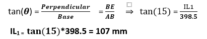
Therefore,
IL2 = IL1 * 2 = 214 mm
IL3 = IL1 * 2 = 214 mm
IL4 = IL1 = 107 mm
Step-7: Find out the Outside Length (OL1) of the First Miter
We know from Pythagoras’s formula,
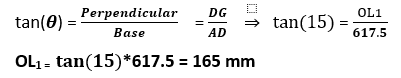
Therefore,
OL2 = OL1 * 2 = 330 mm
OL3 = OL1 * 2 = 330 mm
OL4 = OL1 = 165 mm
Step-8: Find the “Length of Pipe required” for the Miter Bend.
Length of pipe required = CL1 + Cutting allowance + CL2 + Cutting allowance + CL3 + Cutting allowance + CL4
Note- Cutting allowance depends upon the cutting method used, we are assuming 5 mm, refer to Fig. 3.
Thus,
L = 136+5+272+5+272+5+136
L = 831 mm
Step-9: Calculate the Weight of the Pipe.
Check the Plain End Mass in the code book under the code “ASME B36.10 for 8” SCH 120 Pipe (refer to Fig. 4).
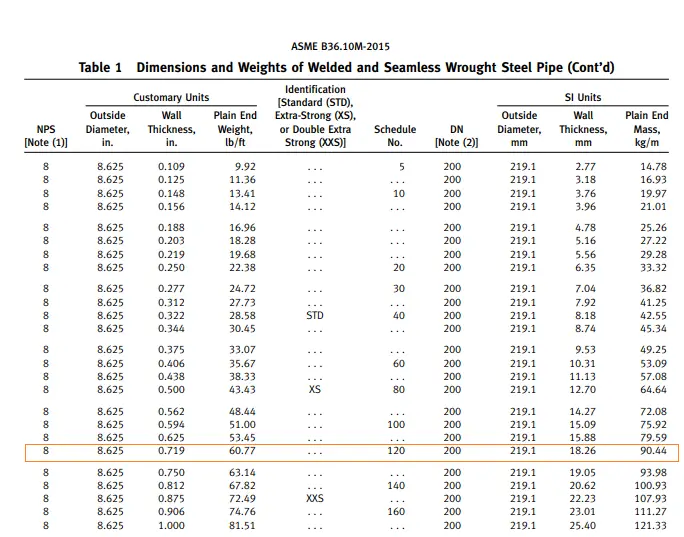
Plain End mass is given 90.44 kg/m as per ASME B 36.10 M
Now,
find the weight using the following formula-
Weight of the Pipe = Plain End Mass * Length of Pipe ( in meters)
Weight (W) = 90.44 * 0.831 = 75 kg.
Step-10: Get the Cut-back (optional).
Cut-back = CL1 – IL1
Cut-back = 136 – 107 = 29 mm
Maximum Allowable Internal Pressure for Miter Bends
Clause 304.2.3 of ASME B31.3 provides equations for calculating the maximum allowed internal pressure for miter bends. The equations are provided for two types of meter bends:
- Single Miter Bend, and
- Multiple Miter Bends
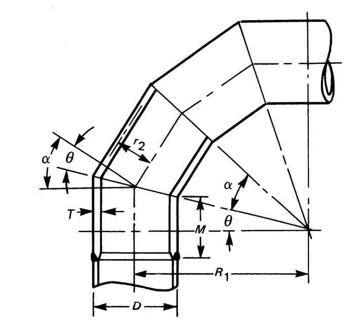
The nomenclature used for the calculations is given in Fig. 5 below:
Formulas for Single Miter Bends
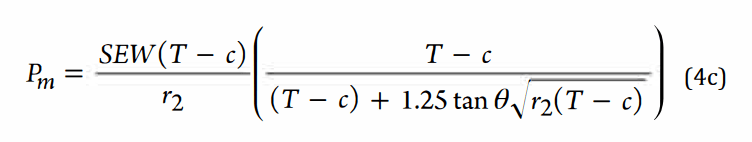
For a single miter bend, the code provides two equations based on the angle of cut (θ):
When θ<=22.5 degrees, the maximum allowable internal pressure for a single miter is calculated using the following equation:
On the other hand, when θ>22.5 degrees, the equation for determining the maximum allowable internal pressure is as follows:
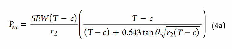
Formulas for Multiple Miter Bends
For multiple miter bends, the maximum allowable internal pressure is the lesser value calculated as per equations 4a and 4b below. These equations are valid for θ<=22.5 degrees.
In the above equations:
- Pm = Maximum allowable internal pressure
- S = Allowable stress for pipe material
- E = Quality factor for longitudinal weld joints in pipes
- W = Weld joint quality reduction factor
- T = Ordering thickness of the pipe as per the Piping Material Specification
- c = Sum of mechanical, corrosion, and erosion allowances
- θ = Angle of the miter cut
- r2 = Mean radius of the pipe = (D-T)/2
- D = Outer diameter of the pipe
- R1 = Radius of the miter bend
Few more useful resources for you.
Piping Elbows vs Bends: A useful literature for piping engineers
Piping Elbow or Bend SIF (Stress Intensification Factor)
Tee Connection: A short literature for piping engineers
Technical requirements for Pipes & Fittings for preparation of Purchase Requisition
“Pipe Coupling”-A short Introduction for the piping professionals
Comparison of Pipe and Tube (Pipe Vs Tube)
Details about Spectacle Blind and Spacers
I am Mechanical Piping & Pipeline Supervisor Engineer with more than 13 years experience relevant in Oil & Gas Indusry EPC Projects.
I am also Hydraulic Engineer.
hydrocarbontransportation@gmail.com
bsaaoui@yahoo.fr
+213770738270
+213673316910
Hello, i Wanna ask about number of cut and number of cuts what a different ?
if i wanna make Elbow 90deg 1200mm for 5 pcs segmented is meaning how many number of cut and cuts ?
Thanks ,
How to do this calculation below
The length of pipe to be cut of 3/4″ pipe that has a 90 and a 45 at each end is _______.
hello , for a single miter bend, how to understand the IL and R?
Mitre bends are not often seen on commercial small-bore
Please Tell me Minimum & Maximum Alowable Defelection Angle in Steel Pipeline Laying Works.
Thank you for the information. Can you assist with the infor on determining the number of miters based on the pressure and temperature of the line?
hi.i wanted to know how it is possible to make a cut to the desired degree in the pipe and different places in PDMS.
for example, cutting a 1 degree in the head of a plain pipe.
thank you.