
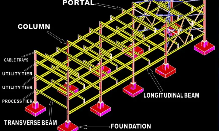
A pipe rack is the main artery of a processing unit. It connects all equipment with lines that cannot run through adjacent areas. Because it is located in the middle of most plants, the pipe rack must be erected first, before it becomes obstructed by rows of equipment. Pipe racks carry process, and utility piping, and also include instrument and electrical cable trays, as well as equipment mounted over all of these. Fig. 1, shows a typical pipe rack.
This is a small presentation on Pipe Rack and Rack Piping. It will be very helpful for beginners in the piping industry. This article will cover the following points in brief:
- Data Required for Pipe Rack Development
- Pipe Rack design criteria
- Shapes
- Future Space
- Width of Pipe Rack
- Clearance
- Pipe Rack Loading
- Rack Piping
- Positions of Lines (Process & Utilities)
- Hot Lines & Cold Lines
- Bigger Size Lines
- Pipe Spacing
- Anchor Bay
- Unit Battery Limit
- Expansion Loops
- Pipe Route
- Trays
What is a Pipe Rack?
A pipe rack is a structural framework designed to support and organize pipes connecting process units and equipment in various industrial and construction settings. Typically constructed from steel and concrete, it holds pipes and instrument cables at an elevated position to facilitate maintenance, prevent damage, and allow for efficient flow and routing of fluids or gases. Pipe racks are commonly used in industries such as oil and gas, chemical processing, and manufacturing, where they help manage the complex network of piping systems essential for operations.
Rack piping design is a very important subject for piping engineers. Designing piping within pipe racks is essential for efficient operation, safety, and meeting regulations. Since the design of the pipe rack structure is closely linked to the rack piping design, both should be considered together.
Data Required for Pipe Rack Design
When designing a pipe rack, we need several documents: the P&ID, Flow Diagram, Plot Plan, Layout Specification, Client Specification, Construction Material details, Fire Protection Requirements, and information about surrounding equipment. The pipe rack design begins with setting the width, spacing, and elevations. After determining these factors, a line routing diagram should be prepared.
The primary data required for the detailed design and development of a pipe rack are:-
- Plot Plan
- P&ID’s
- Client Specification
- Construction Materials
- Fireproofing requirements
- Statutory requirements
Pipe Rack Design Criteria
Shapes of Pipe Rack
There are various shapes of pipe racks like L/T/U/H/Z. These shapes shall be considered based on the area available.
Future Space Requirement in Pipe Rack
The total width of the pipe rack shall include 25% extra space for future expansion/modification in the unit for rack width up to 16 m and 10% for rack width above 16 m. The future space %age is normally based on client requirements.
Width of the Pipe rack
The width of the rack shall be 6 m, 8 m, or 10 m for single bay and 12 m, 16 m, or 20 m for double bay having 4 tiers maximum. The spacing between pipe rack portals shall be taken as 6m in general. However, it can be increased to 8m depending on the size of the pumps to be housed below the pipe rack.
Clearance criteria in Pipe rack
For units, clearance beneath the pipe rack shall be 4 m minimum both in longitudinal and transverse directions.
For Offsite, clearance beneath the pipe rack shall be 2.2 m minimum both in longitudinal and transverse directions.
Road clearance shall be 7 m for the main road and 5 m for the secondary road.
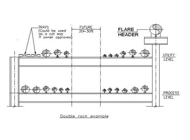
Rack Width Selection Criteria
Refer to Fig. 2 for details
Pipe Rack Loading
Pipe rack loads shall be given by the stress group to the Civil & structural discipline for pipe rack design.
- Sustain Load (Dead Load): Weight of piping, valve, and load insulation
- Thermal Load: Load by thermal expansion of piping & Reaction force by the internal pressure of expansion bellows
- Dynamic Load
- Occasional Loads by the vibration of piping & by wind and earthquake
- Sustained Load (Live Load): Liquid load for the hydrostatic pressure test
Guidelines for Rack Piping
Position of Lines in a Pipe Rack:
Predominantly process lines are to be kept at a lower tier and, utility & hot process lines are on the upper tier.
Hot Lines & Cold Lines in a Pipe Rack:
Generally, hotlines & cold lines are to be kept at different tiers or at different groups on a tier.
Pipe Spacing inside Pipe rack:
Minimum spacing between adjacent lines shall be decided based on the O.D. of the bigger size flange (minimum rating 300# to be considered), O.D. of the smaller pipe, individual insulation thickness, and additional 25mm clearance. Even if the flange does not appear the minimum spacing shall be based on the above basis only. Actual line spacing, especially at ‘L’ bend and loop locations, shall take care of thermal expansion/thermal contraction/non-expansion of adjacent lines. Non-expansion/thermal contraction may stop the free expansion of the adjacent line at the ‘L’ bend location.
Bigger Size Lines:
Large-size lines (14” and larger) shall be arranged close to the column in order to decrease the bending moment of the beam. Water lines more than 30” shall not be routed over a pipe rack, these shall be routed underground.
Anchor Bay in a Pipe rack
Anchors on the racks are to be provided on the anchor bay if the concept of anchor bay is adopted. Otherwise, the anchor shall be distributed over two to three consecutive bays.
Anchors shall be provided within the unit on all hotlines leaving the unit.
Pipe Route:
Racks shall be designed to give the piping the shortest possible run and to provide clear head rooms over main walkways, secondary walkways, and platforms.
Trays:
Generally, the top tier is to be kept for Electrical cable trays (if not provided in the underground trench) and Instrument cable ducts/trays. Cable tray laying to take care of necessary clearances for the fireproofing of the structure.
Battery Limit (ISBL):
Process lines crossing units (within units or from the unit to the main pipeway) are normally provided with a block valve, spectacle blind, and drain valve. Block valves are to be grouped and locations of block valves in the vertical run of the pipe are preferred. If the block valves have to be located in an overhead pipe-way, staircase access to a platform above the lines shall be provided.
Steps for Pipe Rack Piping
- The first step is to create a line-routing diagram. This diagram shows all process piping systems on a general arrangement drawing or unit plot plan where the pipe rack is situated.
- The line-routing diagram is completed using information from the initial P&ID or Process Flow Diagram, including line size, line number, pipe material, and operating temperature.
- After the routing diagram is finished, determine the rack width, column spacing, road crossing span, and the number of levels and their elevations.
- Column spacing should be chosen based on the pipe span economics and truss arrangement to handle road crossings or avoid underground obstacles.
- Design the pipe rack to meet specific plant requirements.
- Calculate the rack width using a typical cross-section, considering that process lines are usually on the lower levels and utility lines on the top. Instrument and electrical trays may be placed on the utility level or a separate level if space allows.
- Include extra space for future growth, typically 25 to 30% more in rack width.
- When flanges or flanged valves are needed on adjacent lines, stagger them to avoid interference.
- Allow for thermal expansion or contraction by providing sufficient clearance where movement will occur.
- Establish the clearance of the first line from the structural pipe rack column based on sizes provided by civil or structural engineers.
- After reviewing all requirements and arrangements, round off dimensions to the nearest whole number. Decide on the width and number of levels, such as a two-tier, 30 ft. wide rack or a three-tier, 20 ft. wide rack.
- Determine the gap between tiers based on the largest diameter pipeline and branching. Ensure there is no interference from support, insulation, or the size of branches. All branch lines should be arranged aesthetically on a common top of steel (TOS).
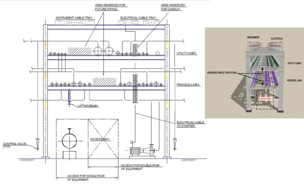
- Finalize the conceptual arrangement of the pipe rack based on these considerations.
Fig. 3 below shows the cross-section of a typical pipe rack:
Lines Routed in a Pipe Rack
Before starting any pipe rack piping project, it’s crucial to categorize the pipelines. In a pipe rack, pipelines are generally classified into three groups: process lines, relief-line headers, and utility headers.
Process Lines:
- Process lines connect nozzles on process equipment that are more than 20 feet apart. Equipment that is closer can be connected directly.
- Product lines transport materials from vessels, exchangers, or pumps to storage or headers outside the plant.
- Crude or charge lines enter the unit and usually run through the yard before connecting to exchangers, furnaces, or other equipment like holding drums or booster pumps.
Relief-Line Headers:
Relief-line headers include relief lines, blow-down lines, and flare lines. These lines should be self-draining, directing fluids to a knock-out drum, flare stack, or plant boundary. Pocketed systems, which require extra condensate pots and additional instruments, valves, and pumps, are costlier. To avoid pockets, some relief headers are placed on higher elevations, supported by extended pipe rack columns. However, for non-condensing gas systems, self-drainage may not be as critical.
Utility Lines:
Utility lines are divided into two groups:
- Utility Headers: These serve the entire plant and include low and high-pressure steam lines, steam condensate lines, plant air, instrument air, and potentially cooling and service water lines.
- Utility Lines: These lines serve specific equipment or groups of similar equipment. They include boiler feedwater, smoothing steam, compressor starting air, fuel oil lines, lubricating oil, cooling oil, fuel gas, inert gas, and chemical treatment lines.
For effective condensate collection, steam headers should drain to a steam separator. Branch connections to steam headers are usually placed on top to prevent condensation from reaching the equipment.
Expansion loops in a Pipe Rack
Refer to Fig 4.
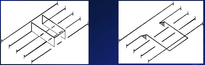
The expansion loop is provided on the high-temperature lines. This information shall be given by the stress group. All the loops shall be located around one column only.
Make lines into a group and install large-size piping and high-temperature piping to the edge of the pipe rack. When necessary to install an expansion loop on the condensate line, do it horizontally to prevent water hammering. But do as above if the horizontal loop is impossible.
To learn the piping stress concepts of pipe rack design, visit the following article: Rack Piping for a Piping Stress Engineer
Types of Pipe Racks
Pipe racks come in various types, each designed to meet specific needs and conditions in industrial settings. Here are some common types:
- Single-Tier Pipe Racks: These racks have one level and are typically used for smaller installations or where space is limited. They are often used for utility lines or less complex piping systems.
- Multi-Tier Pipe Racks: These racks feature multiple levels, which allow for the separation of different types of lines (e.g., process lines on lower tiers and utility lines on upper tiers). Multi-tier racks help optimize space and organize complex piping systems.
- Modular Pipe Racks: Modular racks are pre-fabricated in sections or modules, which can be assembled on-site. This type of rack is flexible and can be easily expanded or reconfigured as needed.
ISBL Pipe Rack vs OSBL Pipe Rack
In industrial piping systems, ISBL (Inside Battery Limits) pipe racks and OSBL (Outside Battery Limits) pipe racks are two key categories that differentiate between the locations and functions of pipe racks within a plant or facility.
ISBL Pipe Racks (Inside Battery Limits):
ISBL pipe racks are located within the battery limits of a processing unit or plant section. These racks are found inside the core area of the facility where the main processing equipment and operations are situated.
They support process lines that are crucial for the internal operations of the plant, such as transporting chemicals, gases, or other materials between equipment like reactors, exchangers, and distillation columns.
ISBL pipe racks are designed to handle more complex piping systems and must accommodate the specific needs of the internal process. They often require careful planning to ensure that they do not obstruct operations or maintenance.
OSBL Pipe Racks (Outside Battery Limits):
OSBL pipe racks are located outside the battery limits of the processing unit or plant section. These racks are found in the peripheral areas of the facility, typically in the utility or service areas.
They support utility lines and other ancillary systems that are not part of the core processing but are essential for overall plant operations. This can include lines for steam, water, electricity, and other utilities that serve the entire facility or connect to external systems.
OSBL pipe racks are generally designed for simpler and less critical piping systems compared to ISBL racks. They often deal with less complex routing and must account for factors like accessibility and integration with the external parts of the plant.
In summary, ISBL pipe racks are integral to the plant’s core processes, while OSBL pipe racks manage supporting utilities and external connections. Each type plays a crucial role in ensuring the efficient operation of the plant.
Pipe Rack Structural Design
The structural design of pipe racks is performed by the civil team using piping loads given by piping stress engineers, equipment loads (Air cooled heat exchanger and others) by mechanical engineers, and cable loads by electrical/instrumentation engineers. If you are interested in learning more details about the structural design, then visit: Design of Structural Steel Pipe Racks
I want to know if is necessary to interconnect the estructure of pipe rack with cable jumps (joining bolts) in order to quaranty electrical continuity and in some places connect to the earthing system.
The pipe rack structure is carbon steel painted.
The pipe rack if to support gas piping
Wonderfully crisp writing. Pls keep it up. Thank you very much for sharing knowledge.
Thanks for your support,
The total width of the pipe rack shall include 25% extra space for future expansion/modification in unit for rack-width up to 16 m and 10% for rack-width above 16 m. The future space %age is normally based on the client requirements
Total width 16 m , is single tier width or addition of all tier e.g. 8m+8m=16 or 6m+6m+6m=18m
2)while taking future space percent of width. whether width is center to center distance or actual occupied space.
Hi Anup,
this left me a question, since it’s “generally..” is there any standard or code that you have been referred or used before?
“Trays:
Generally, the top tier is to be kept for Electrical cable trays (if not provided in the underground trench) and Instrument cable ducts/trays. Cable tray laying to take care of necessary clearances for the fireproofing of structure.”
Hi Anup,
I need a technical reason why we can’t keep the cable trays beneath the pipe rack.
A general practice I seen cable trays always kept wither parallel or above the pipe.
Can you pleas explain.
Regards,
Manik
Hi Manik,
Typically, one does not locate cable trays under piping, as if there is a leak or pipe failure, the electric cables are not at risk.
Hi Anup,
I did want to ask, when looking at future expansion (30% growth) on the pipe rack.
If one has 3 level on the rack, does one need 30% per level or can one accumulate (10% per level)?
The requirement of future expansion will be same on all the tiers.