
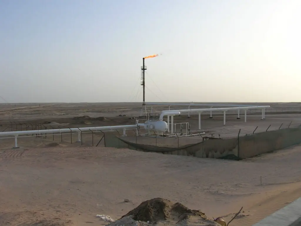
A Flare system is a means of safe disposal of waste gases by burning them under controlled conditions. Flare piping generally comprises of PSVs outlet piping, subheader piping & main header piping.
Design conditions considered for stress analysis are as per P&IDs, line list, and specific information related to flare if any by the process. A typical flare system consists of:
- PSV outlet pipes, subheader connected to main flare header, main flare header connected to knock out drum, the outlet of the flare knock-out drum to flare stack.
- A knockout drum to remove and store condensable and entrained liquids.
- Single or multiple burner units and a flare stack.
The important points that a stress engineer should consider carefully are listed below:
Fluid Density of Flare Lines
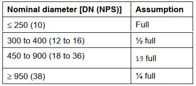
The Fluid density has to be taken from the Line list (Process Department). However, the density given in line designation tables (LDT) is normally very less. But different specification says to use an assumed liquid content while stress analysis of flare system lines. For example, Shell DEP 80.45.10.10 says to assume the following liquid content for stress analysis and support design load considerations.
Pressure Test Method for Flare Lines
Flare lines are normally pneumatic tested. So, hydro test weight is not required to be considered during stress analysis. However, in specific cases, water-filled weight may be considered (Check with the Process department).
Supporting Flare Lines
Flare lines are normally provided with pipe slopes as per Process requirements/ Project specifications. So general practice is to support with Shoe/saddle supports. The pipe supporting span is to be maintained so that the sustained sagging should not exceed 5 mm (preferably below 3 mm). The structure below the pipe support/shoe height is to be planned to meet the piping sloping/free draining requirement.
Stress Intensification Factor or SIF consideration
Normal industry practice is to take 45 degrees/90-degree branch connections from Flare Header: Proper SIF (both in-plane and out-plane) should be incorporated at branch connections while entering data into the analyzing software. SIF s can be calculated using Fe-SIF, Nozzle Pro, or some other type of FEA software. Sometimes reinforcement may be required to reduce the SIF value. In absence of proper SIF values of 45 Degree Branch connections through FEA software, many organizations suggest a SIF value for a 45° branch connection as 2.25 times the SIF value of a 90° branch.
It is also to be noted that due to less design pressure, flare header thickness is normally less. And it may exceed the ASME B31.3 limitation of D/t ratio within 100. Special analysis methods are to be exercised for flare headers when the D/t ratio exceeds 100. Click here to know the applicability of Caesar II software for stress analysis when D/t exceeds 100.
Temperature Gradient
In a flare system sometimes a temperature gradient or profile may exist when the hot contents flow into the subheader / main header which is at a lower temperature ( confirmation with the process if required ).
Also, note that the minimum design temperature for flare headers is normally in the range of -50 Deg C. So there will be a wide difference between the maximum and minimum design temperature. So decide on expansion loop locations early in the project stage.
PSV/PRV Reaction Force
There are many PSV/PRVs that are connected to the flare header. It is always a better practice to consider all the PSV systems in a single system along with the flare header to get proper boundary conditions for all PSV/PRV systems. The reaction force for those PSV/PRVs needs to be collected/calculated beforehand. It is preferable to add Rest+Guide+Line Stop in the PSV outlet line and Hold down +Guide in the PSV inlet line. The reaction force is to be added considering one PSV/PRV is popping up and the other is not popping.
Piping Flexibility
Piping shall be evaluated for sufficient flexibility. If necessary expansion loops shall be provided. Expansion joints are to be avoided. Flare piping loops are planned in a horizontal plane (2D loops) in order to ensure pipe slope/free draining requirements. However, the number of loops should be minimized as much as possible.
- Flare line routing and supporting are to be planned in such a way that forces and moments on flare knock-out drum nozzle connections are minimized.
- Sometimes Flare line may consist of a two-phase flow. So Vibration/Acoustic analysis (AIV) is required to be performed and supporting to be strengthened.
Flare Stack and Knock Out Drum Nozzle Loads
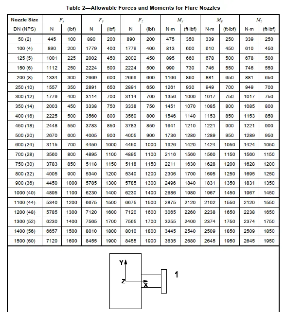
Knock-out drums are normal horizontal vessels and normally have high allowable nozzle load values. So there is no difficulty in qualifying these nozzles. But, Stack has low magnitude nozzle allowable loads. So pipe routing has to be sufficiently flexible to reduce the nozzle loads. Consult with the flare stack vendor at the initial stage and collect the allowable load values early to avoid major design changes at a later stage.
API 537 standard, Table 2 provides some typical values for Flare stack allowable nozzle loads and moments based on nozzle sizes. A part of the flare stack allowable nozzle loads from API 537 standard is reproduced here.
Few related articles for you.
Elevated Flare systems used in Process Industries
Routing Of Flare And Relief Valve Piping: An article
Pre-Commissioning and Commissioning Checklist for Flare Package
Can you please explain the 4D loop?
Very useful content
How flare stack to be modeled? Are load cases different or any additional case? can we apply WRC ? if stack or drum failing? which PSV should be considered to be pop up? will solar radiation to be considered for piping?
Very interesting and useful content. Thanks for sharing.
Sir, May I know in general whether the flare branch lateral connection shall be set in or set on type.. Thank You!