The function of a Storage Tank
A storage tank is one of the most important static equipment used frequently in tank farm areas to store liquids for further processing or use. They serve two important functions:
- Serves as a container to store fluids and
- Provide a pressure head for further distribution of the stored product.
For processing plants (refineries, chemical and petrochemical complexes, etc ), Storage tanks find their uses in several phases like
- to store the feed (For example Crude Oil) before processing
- to hold partially processed products and
- to collect finished products.
In every plant, a number of storage tanks are used. Hence, a good arrangement of these storage tanks not only saves land space but also reduces the cost of a plant.
What is Nozzle Orientation?
Each tank has several nozzles to allow the Fluid in or out. All these nozzles must be arranged in a cost-effective efficient way such that they work smoothly without overloading the nozzle connections during operation. Proper nozzle orientation of storage tanks helps in reducing the maximum of operational problems. Good nozzle orientation is thus one of the most important activities in the piping layout and design stage.
Considerations for Storage Tank Nozzle Orientation
The number of tank nozzles is dependent on the operation and fluid handled. The orientation of each nozzle and providing platforms shall be considered together.
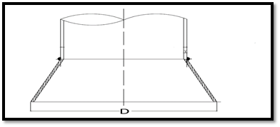
Normal practice is to collect body (shell) nozzles on one side of the tank and roof tanks in the same direction along with of roof platform (Fig 1). By this design, these nozzles and the valves, connected to each nozzle are easily accessible. Lesser platforms are required in such cases. Hence, the design is economic.
However, there are some exceptions like the tank manhole. It is better to locate the manhole in a different direction to other nozzles, the reason being easier entrance and exit.
A proper understanding of the fluid flow concept and nozzle performance helps the piping design engineer with better nozzle orientation design.

Manhole of the Tank
Manholes are provided for frequent maintenance purposes. So it must have good access. It has to be provided based on the requirements set forth in the contract specifications. Locate manholes close to the dike accessway, far from the pipe way, and also accessible from the ground then operators can enter and exists easily.
Sealed and Vented manholes are to be provided at strategic points of the tank system when separate major groups of storage tanks, process blocks, and loading facilities are involved.
Two types of tank-shell maintenance access openings are used: the standard and the round opening. The large tanks or those that use internal heaters normally use the larger, oval-shaped, flat-bottom opening.
The access opening area must be kept free of any obstructions like large pipe supports, piping, and light poles.
Orienting the Input/output nozzles
The main process nozzles of a tank are input/output nozzles. The main point, where there is no other process requirement, is the minimization of pipe length (and so pressure drop). For example, sometimes it is required to locate these nozzles on different sides of the tank to mix fluid inside of the tank. Nozzle elevation also affects orientation; locating the elevated input nozzle and output nozzle in the same orientation vapor, which is soluted during the falling of liquid, will make gas traps in piping or cavitations in pumps. In Fig 1, A1 stands for the inlet and B1 for the outlet nozzle.
In Fig 1, A3 is the recycling or circulation nozzle used for circulating fluid via the outlet nozzle and pump then entering the tank through this nozzle, when the risk of freezing, choking or sedimentation of tank fluid exists. Consideration for the orientation of this nozzle is the same as the inlet nozzle.
Consideration for Tank Draw-off Nozzle
For Storage tanks in hydrocarbon services, to permit periodic draw off of water which normally collects in the product, an API low-type shell nozzle, and a drain valve are normally provided at the bottom of the tank. The water draw-off valve is normally positioned over an open concrete box with an outlet discharging into the gravity oily water collection system. For this nozzle, consideration of OSW lines is mandatory, to use less sump and pits in this system. In a group of tanks that are in one row, this nozzle can be located on the same side. In Fig 1, D1 is a draw-off nozzle.
Sampling Nozzles
A manual gauging-sampling well may be used where the stored product, is specified as a static accumulator. Gauge well shall be burr-free. If a manhole or a separate roof connection is used for gauging-sampling purposes it shall be located near roof support. All sampling valves shall be accessible and since valves are to be installed as close as possible to nozzles, so all nozzles shall be accessible. Normally, samples can be taken two liters per at 3 points at upper, middle, and lower levels daily. So, sample points are normally located at the grade, top platform, or along with the stair landings. In Fig 1, S1 and S2 are sampling nozzles to be accessible.
Level Nozzles
Minimum, one internal float level gauging instrument per tank, readable from grade consider. Other level gauges shall be readable and all their connection shall be maintainable, so nozzles are to be located along stairs.

Temperature Indication Connections
Connections for temperature indication shall be furnished for a flanged or threaded thermowell installation accessible for removal of the well and required space shall be considered in front of it. (Nozzle T1 in Fig 1)
Breathing and Safety Valves nozzles
Each tank has a minimum of one safety valve and one breathing valve, which is very important for tank safety during its life, installed on top of the roof shall be accessible from a platform. Also valves of an inert gas line which is connected to the tank for pressure balance when considered. In Fig 1, SV1 and BV1 are located close to the platforms.
Tank Mixers and heaters
When on a tank, a mixer or a tube bundle heater is installed via a nozzle, orientation of it shall provide adequate area for removal and easy movement to the outside of the dike.
Fire Fighting Nozzles
Do not forget that fire water is never injected directly inside the tank, so the only nozzles are related to the foam system if existing. The most important point that shall be considered during the design of nozzle orientation for these systems is the number of nozzles and also the fact that nozzles shall be in a symmetrical arrangement to provide uniform coverage of foams.
Implementation of the above points in the design, will reduce the number of structural attachments to the tank and also the capital costs of the plant as well as operational problems and increase personnel safety.
Few more useful resources for you..
Articles related to Tanks
Articles Related to Pumps
Articles Related to Exchangers
Piping Design and Layout basics
Piping Stress Analysis Basics
Piping Materials Basics
Articles related to Process, Civil, Mechanical and instrumentation Design
About the Author: The author of this article is Mr. Amir Razmi, an International, a dynamic and multi-functional chemical engineer with 14 years’ experience in engineering and EPC of oil and energy projects from pre-contract activities to execution, and closeout. The author has added the above article as a part of his book “Storage Tank Farms Layout and Piping” which you can purchase by clicking here.