Shell and Tube heat exchangers are frequently used in Oil & Gas, Power plants, Refineries, and Chemical and Petrochemical industries. As piping systems connected to such equipment are considered Critical, piping stress engineers need to model it quite frequently. But sometimes, specifically for new stress engineers, the modeling steps seem to be very difficult. In this article, I will try to illustrate the modeling considerations in caesar II.
Heat exchanger with an expansion bellow in the shell.
The thermal profiling considerations i.e, the temperature distribution during Caesar II modeling is different in both cases.
Inputs required for Modeling
Before modeling the equipment the
following details need to be collected.
Equipment GA drawing with all dimensions.
Fixed and Sliding saddles.
Shell side inlet and outlet design parameters.
Channel or tube side inlet and outlet design parameters.
Modeling of the Heat exchanger without expansion bellow
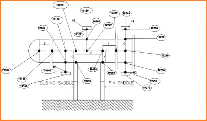
Caesar II modeling of heat exchangers that do not have an expansion bellow is quite easy. Better engineering practice is to model the equipment as a rigid body. Refer to Fig. 1 and the Table below that simultaneously for modeling the elements as shown.
Fig. 1: Schematic of Shell & Tube Heat Exchanger without bellow
Region
Node No
OD & Thickness
Process Parameters
Temperature
Material
Length
Remark
Fixed Saddle (A)
10000 to 10020
Shell
Shell
( Tis + Tos ) /2
Shell
Shell OD/2 i.e Length A
Fixed Anchor at node 10000
Part of Shell in between Fixed and Sliding saddle
(B)
10020 to 10070
Shell
Shell
( Tis + Tos ) /2
Shell
Length B from equipment GA
Sliding saddle (C)
10070 to 10090
Shell
Shell
( Tis + Tos ) /2
Shell
Shell OD/2 i.e Length C
Hold Down + Guide at node 10090
Shell part after sliding Saddle (D)
10070-10110
Shell
Shell
( Tis + Tos ) /2
Shell
Length D from Equipment GA
Channel Length (E)
10110-10120
Channel
Tube
( Tit + Tot ) /2
Channel
Length E
Remaining Shell after Fixed Saddle (F)
10020-10200
Shell
Shell
( Tis + Tos ) /2
Shell
Length F from GA
Channel Length (G)
10200-10210
Channel
Tube
( Tit + Tot ) /2
Channel
Length G
Here
Tis = shell inlet temperature
Tos = shell outlet temperature
Tit = tube inlet temperature
Tot = tube outlet temperature
Modeling the Equipment Nozzle Connection
Modeling steps are shown for Nozzle N1
At first, model a rigid element from node 10210 to 10219, other parameters will same as the region (i.e, channel region G in this case). Then put the anchor at node 10220 and connecting node 10219.
Then model from 10220 to 10230 as the pipe element with all mechanical and physical properties of the nozzle (refer to mechanical datasheet)
Then model the element 10230 to 10240 as a flange element with all mechanical and physical properties of the flange (refer to mechanical datasheet).
All other nozzle modeling procedures will be similar to nozzle N1 modeling.
From node 10240 onwards connected piping can be modeled.
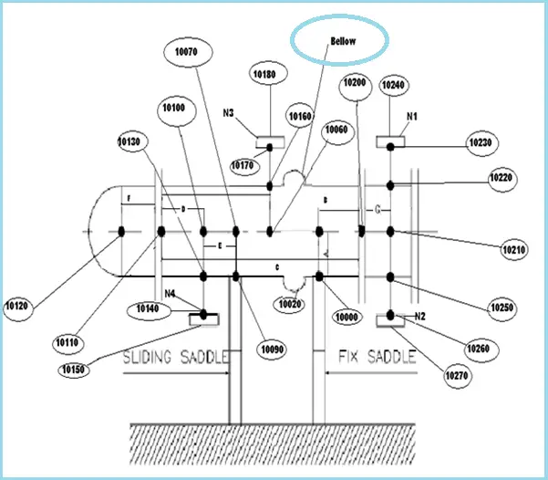
Modeling of the Heat exchanger with an expansion bellow in the shell
Refer to Fig. 2 and Table below that simultaneously to model the elements as shown.
Fig. 2: Shell and Tube Heat exchanger with an expansion bellow in the shell
Region
Node No
OD & Thickness
Process Parameters
Temperature
Material
Length
Remark
Fixed Saddle (A)
10000 to 10020
Shell
Shell
( Tis + Tos ) /2
Shell
Shell OD/2 i.e Length A
Fixed Anchor at node 10000
Part of Shell in between Fixed Saddle and Channel
(B)
10020 to 10200
Shell
Shell
( Tis + Tos ) /2
Shell
Length B from equipment GA
Complete Shell Length (C)
10200 to 10110
Shell
Tube
( Tit + Tot ) /2
Tube
Length C from GA
Shell Part in between Nozzle N4 and channel (D)
10110-10100
Shell
Shell
( Tis + Tos ) /2
Shell
Length D from Equipment GA
Shell Part in between Nozzle N4 and sliding
saddle (E)
10100-10070
Shell
Shell
( Tis + Tos ) /2
Shell
Length E from GA
Sliding Saddle
10070-10090
Shell
Shell
( Tis + Tos ) /2
Shell
Shell OD/2
Hold Down and Guide at node 10090
Channel part (F)
10110-10120
Channel
Tube
( Tit + Tot ) /2
Channel
Length F from GA
Channel part (G)
10200-10210
Channel
Tube
( Tit + Tot ) /2
Channel
Length G from GA
Nozzle is to be modeled in the same way as shown for the above Heat exchanger.
Few companies model the Saddle/Skirt part from the bottom of the shell. In that case rigid element is to be modeled from nodes 10000 and 10090 with saddle length as per GA. (Different saddle temperatures are to be considered for these elements, However, shell material, OD, and thickness can be considered for modeling this part.). In such a situation, the fixed anchor and hold down+guide supports need to be considered at the bottom of the saddle.
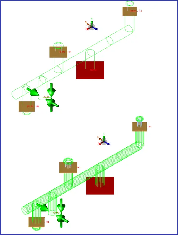
A sample model is shown in Fig. 3 below.
Fig. 3: Sample Shell and tube heat exchanger model in Caesar II
Bolts and Nuts are fasteners for joining two parts. Even though bolted joints are not permanently similar to welded joints, still they are used in industries to a large extent wherever there is a need for separation of the parts. Process, Power, and Steel Industries can not be thought of without Nuts and Bolts. But one of the major problems with Bolted joints is external corrosion due to the working environment.
How to Protect Bolts from Corrosion
Corrosion of nuts and bolts is a major concern for industries. One of the major causes of bolt failure and loose bolt is Extreme Corrosion. The use of Corrosion Resistant material is one option to prevent bolting corrosion but that translates into huge costs. So this is normally not suggested for Carbon or alloy steel piping. Use of bolt cap is another option that can be used for bolt sizes between 1/2 inch to 6 inches. But the most cost-effective way to increase bolt life from corrosion is by using corrosion-resistant coatings. In this article, I will highlight some important points for coating selection.
Types of Bolt Coatings
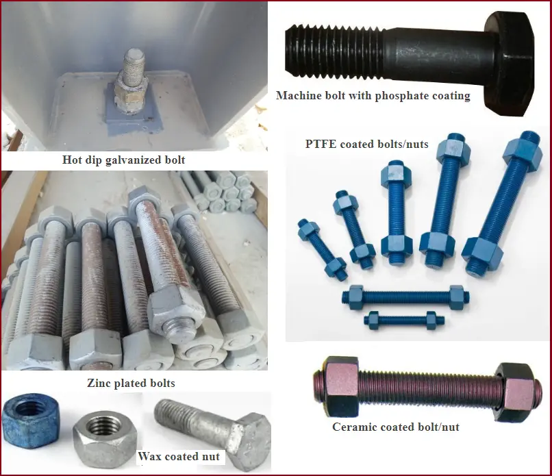
Various coating methods (Fig. 1) are used in industries. However, the most frequently used methods along with governing coating standards are listed below:
Fig. 1: Various Types of Bolt Coatings used in Industry
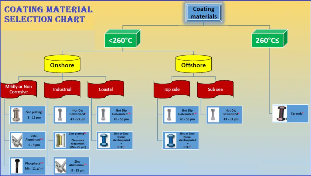
Refer to Fig. 2 below. The image provides a quick guide for selecting coatings based on their application and operating temperature range. Refer to the General Notes and Special Notes mentioned at the bottom of the image while selecting the coating materials.
Fig. 2: Bolt and Nut Coating Material Selection Guide Chart
General Notes for Coating Selection Chart
This chart is just a recommendation, other coatings may be used based on successful experience.
These coatings are normally applicable to carbon or low alloy steel bolting. CRA bolting is not included in the chart.
In the selection of coatings, their cost has been also considered.
Hydrogen embrittlement may occur on fasteners caused by hydrogen, introduced from chemical cleaning, pickling, or coating process e.g. electrolytic plating and Hot Dip Galvanized. Such coatings may need pretreatment/post-treatment.
Fasteners should be avoided in splash zone applications. However, when this is unavoidable, fasteners shall be made of seawater-resistant material, e.g. alloy 625/725 or similar.
Cadmium coating is still being used; however, due to the hazardous nature of the plating process and exposure to the environment, it is being phased out.
Wax-based systems may be used as maintenance systems.
For Hot Dip Galvanized coating, the Dip spin procedure should be applied.
Special Notes for Coating Selection Chart
Refer to the Numbers mentioned in Fig. 2.
Zinc-plated, Hot-dip Galvanized, and phosphate coatings should not be used at continuous temperatures above 200˚C.
Zinc/Aluminum coating is normally known under registered trademarks such as DACROMET, GEOMET, etc.
Zinc/Aluminum coating may be used up to 300˚C by manufacturer approval.
Phosphate coatings are normally used as a pretreatment to other coatings but may be used in noncorrosive or mildly corrosive areas especially when a sealer is used.
Zinc plating + chromate treatment may be used in the coastal area for short-term applications (less than 10 years) or for long-term applications when they are painted.
Hot Dip galvanized coating may be painted to the extent of its life in marine atmospheres.
Most PTFE coating can be used up to 230˚C, but they may be used up to 260˚C by manufacturer approval.
For subsea applications, the coating of low alloy bolting materials protected by CP is unnecessary. However, thin metal (hot spun galvanized or zinc‐nickel electroplate) is often specified to preserve the bolt surface prior to or during installation.
Ceramic coating for marine applications shall be top-coated. The average coating thickness shall be 20‐30 μm. The base coat can be aluminum particles dispersed in a liquid binder of chromate /phosphate compounds. The top coat can be ceramic oxide pigments dispersed in a liquid binder of chromate/phosphate compounds.
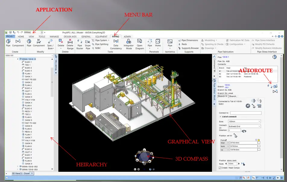
E3D is a 3D piping design software that integrated the good features of PDMS, AutoCAD, and SP3D into a single module. So, obviously, this is the next-generation most advanced software. Developed by AVEVA, The software is designed for a powerful 3-Dimensional design solution experience. Its clash-free multi-discipline design interface (Fig. 1) will reduce the design cost by minimizing rework and maximizing engineering and design efficiency. Moreover, the software is very easy to adopt and it provides the best project execution capabilities. The software is becoming very popular among piping designers circle.
Fig. 1: E3D Design Interface
Features of E3D
Some of the main features of this powerful 3D software are listed below:
Aveva E3D combines all the best features of PDMS, Autocad, and SP3D.
It is much faster and easier than other 3D software that is currently in market use.
It is very user-friendly.
E3D introduces the Auto-Route button (Refer to Fig. 1) which minimizes the time for the pipe routing.
Laser scan models can be accessed directly in E3D without requiring LFM software to open the scan model.
Introduced the Clip option which reduces the complication of complex projects.
Structural, Primitive modification has been simplified.
In-Draw 3D-model can be viewed by tool 3D-Edit
Pipe Modeling in E3D
Pipes are termed veins of any oil & gas plant. So designing pipes and modeling those following design codes and established best practices are very important. In this video tutorial, we will see how the piping is modeled using E3D software.
There are two videos. The first one explains the pipe modeling in the conventional method and 2nd video will explain the pipe modeling using the Auto-Route button.
Oil Rich Gulf Market is always a dream for many engineering professionals across the world. Mainly oil and gas professionals are attracted to work in Gulf Countries at least once in their job career and earn a sufficient amount of money to be settled in their home country.
Although it is not true for maximum engineering professionals, still job seekers want to get a first-hand experience of the Gulf Career. Hence, there is a huge competition among all engineering professionals for middle east jobs. And if the country is the United Arab Emirates (UAE) then simply imagine what the competition will be!
UAE is a beautiful country and for many years they are welcoming expatriates. Three of the highly developed cities; Dubai, Abu Dhabi, and Sharjah are expanding their engineering sector always and are flooded with jobs. Several giant EPC companies are operating in any of the above three cities of UAE. In this article, I am listing down a few of the top EPC companies in Abu Dhabi, Dubai, and Sharjah where interested EPC professionals can try their luck for their career exposure.
Kind request to readers to add more company names and update the HR mail ids in the comments section to help fellow job seekers.
Sr No
Company Name
Region
Office Address
Phone No
HR Mail ID
1
Petrofac
Sharjah
New Al Taawun Rd – Sharjah – United Arab Emirates
+971-6574-0999
inayath.basha@petrofac.com
2
Adnoc
Abu Dhabi
ADNOC Head Quarters Building – Corniche Rd – Abu Dhabi – United Arab Emirates
+971-2707-0000
3
Dodsal
Dubai
Dodsal Group P.O.Box: 8034 25th Floor, UBora Towers Business Bay Dubai United Arab Emirates
+971-4503-8000
recruitment@dodsaldxb.ae
4
Mcdermott
Dubai
+971-4883-5100
5
Atkins
Sharjah
PB.No 7774 – Block A4, (1-4) – Sharjah – United Arab Emirates Phone:
+971-6517-8666
6
Worley
Abu Dhabi
Level 13, Dhafir Tower, Fatima Bint Mubarak Street, Abu Dhabi, United Arab Emirates
+971-2495-1100
7
SNC Lavalin
Abu Dhabi
10th St – Abu Dhabi – United Arab Emirates
+971-2417-1222
Charu.Sharma@snclavalin.com
8
NPCC
Abu Dhabi
Plot No. 71, St 7, Zone 6 – Abu Dhabi – United Arab Emirates
+971-2554-9000
9
L&T ECC
Sharjah
Sheikh Saqr Bin Khalid Al Qasimi St – Sharjah – United Arab Emirates
+971-6517-2900
10
China Petroleum
Dubai
Ground Floor, Building No. 1 & Bldg. 2 6th Floor, Emaar Business Park – Sheikh Zayed Rd – Dubai – United Arab Emirates
+971-4457-8372
11
TechnipFMC
Abu Dhabi
Guardian Office Tower, 4th Street, Shaikh Sultan Bin Zayed Road – Abu Dhabi – United Arab Emirates
+971-2611 6000
12
Lamprell Energy
Dubai
+971-4803-9308
13
Penspen
Abu Dhabi
2nd, 3rd & 4th floors Business Avenue Tower Al Salam Street – Abu Dhabi – United Arab Emirates
+971-2679-2526
14
CH2M HILL
Abu Dhabi
Madinat Zayed office tower, between Tasheel and Petrol pump – Muroor Rd – Abu Dhabi – United Arab Emirates
+971-2401-3800
amit.singh@ch2m.com
15
Wood Group
Abu Dhabi
+971-2555-3045
16
Exterran
Abu Dhabi
Airport road near Corniche, UNB bank building, Syscoms college building, Office #1804 – Abu Dhabi – United Arab Emirates
+971-2641-1823
dolly.srimani@exterran.com
17
Siemens
Abu Dhabi
Building B-05, Siemens Building, Masdar City, Opp. Presidential Flight – Abu Dhabi – United Arab Emirates
+971-2616-5100
18
Litwin PEL
Abu Dhabi
Musaffah – Abu Dhabi – United Arab Emirates
+971-2507-0100
rani.thomas@litwinme.ae
19
Tebodin
Abu Dhabi
Hamdan Bin Mohammed St – Abu Dhabi – United Arab Emirates
+971-2406-6000
20
DUNCAN & ROSS
Dubai
Level 705, U Bora Towers – Commercial Tower – Dubai United Arab Emirates
+971-4311-7800
21
Gulf Petrochem
Sharjah
11 E 11 – Sharjah – United Arab Emirates
+971-6526-4944
22
Bechtel – Middle East
Abu Dhabi
+971-2699-8400
23
Descon Engineering
Abu Dhabi
Floor # 10 Prestige Tower-17 Adjacent to Capital Mall Muhammad Bin Zayed City – Abu Dhabi – United Arab Emirates
+971-2694-6000
24
Kentz
Ajman
Kentz Group. P.O.Box 3505, Ajman, U.A.E.
+971-6743-9233
25
Maire Tecnimont
Abu Dhabi
Street # 10 – Abu Dhabi – United Arab Emirates
+971-2645-0988
26
Mott Macdonald
Abu Dhabi
Al Ghaith Tower – Hamdan Bin Mohammed St – Abu Dhabi – United Arab Emirates
+971-2401-5333
27
National Engineering Services
Abu Dhabi
Office # 1202,12th Floor, Sky Tower, Reem Island – Abu Dhabi – United Arab Emirates
+971-2815-7777
28
Petrojet
Abu Dhabi
4 Sultan Bin Zayed the First St – Abu Dhabi – United Arab Emirates
+971-2628-2138
29
Samsung Engineering
Abu Dhabi
42 floor, Addax Tower, Reem Island – Abu Dhabi – United Arab Emirates
+971-2676-2323
30
Target Engineering
Abu Dhabi
10th Floor, Al Badie Commercial Tower – Al Falah St – Abu Dhabi – United Arab Emirates
+971-2205-2222
31
Galfar
Abu Dhabi
Plot No: 129 & 131, Sector MW4, Mussafah Industrial Area – Abu Dhabi – United Arab Emirates
Vortex flow meters have become an integral part of industrial measurement technology. Their ability to measure fluid flow rates accurately and reliably makes them invaluable in various applications, from water treatment to chemical processing. The Vortex Flow Meter is one of the various types of volume flowmeters that are used frequently in the oil and gas industry to measure the flow inside a pipe. This device performs its best when introducing moving parts poses a problem. The main advantage of Vortex flow meters is that
Sensitivity to process conditions variations is low
low wear compared to other types as there are no moving parts and
applicable for a wide range of fluids, i.e. liquids, steam, and gases.
In this comprehensive guide, we will delve into the principles of vortex flow measurement, their design and operation, applications, advantages, and limitations.
What is a Vortex Flow Meter?
A vortex flow meter is a device used to measure the flow of fluids—liquids and gases—based on the principle of vortex shedding. When a fluid flows past an obstruction, it creates alternating vortices downstream of the obstruction. The frequency of these vortices is proportional to the flow rate, allowing for accurate measurements.
How Vortex Flow Meters Work
Vortex meters are frequency meters that work based on the vortex principle. A bluff body (disturbing element) is placed in the middle of the pipe inside each vortex flowmeter that disturbs the flow causing an obstruction. Downstream of the obstruction, a mechanical sensor is placed which can measure the pressure differences (frequency) in the flowing fluid.
The Principle of Vortex Shedding
The principle of vortex shedding was first described by the German scientist Heinrich Gustav Magnus in the 19th century. When a fluid encounters an obstruction, it generates swirling eddies or vortices on either side of the obstruction. These vortices alternate sides, creating a pattern of vortices that can be measured.
The frequency of vortex shedding (f) can be described by the following formula:
f=K⋅Q/d2
Where:
K is a constant dependent on the shape of the obstruction,
Q is the volumetric flow rate,
d is the diameter of the obstruction.
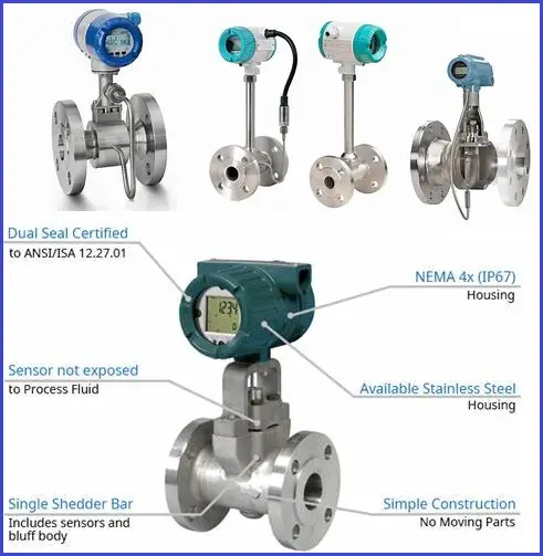
Fig. 1: Typical Vortex Meters
Components of Vortex Flow Meter
On average, every vortex meter consists of the following electronic parts-
Shedder Bar: The obstruction in the flow path that generates vortices.
Sensor: Detects the frequency of the vortices. It can be a piezoelectric or capacitive sensor.
Transmitter: Converts the frequency signal into a flow rate reading, which is displayed on a digital interface.
Body: The casing that holds the internal components and connects to the piping system.
Pick-up elements,
Microprocessor
AC-pre amplifiers,
Noise abatement features,
AC-amplifier with filters,
Schmitt Trigger,
Factors Affecting Vortex Meter Performance
In general, Vortex Meter
performance is influenced by
corrosion of upstream piping
sheddar bar geometry changes due to erosion or wax deposits
positional changes of sheddar bar when improperly
secured
Hydraulic noise, etc.
Types of Vortex Flow Meters
Vortex flow meters come in various configurations to suit different applications.
Full-bore Vortex Flow Meters
Full-bore vortex flow meters are designed for use in pipelines with a consistent diameter. They provide high accuracy and are commonly used in larger industrial applications.
Insertion Vortex Flow Meters
Insertion vortex flow meters are designed for applications where space is limited. They can be inserted into existing pipes without the need for extensive modifications, making them suitable for retrofitting.
Vortex Flow Meter Design
A vortex flow meter is typically constructed from 316 stainless steel or Hastelloy and consists of a bluff body, a vortex sensor assembly, and transmitter electronics, which can also be mounted remotely. These meters are commonly available in flange sizes ranging from ½ inch to 12 inches. For installations under six inches, the cost of vortex meters is competitive with that of orifice meters. Wafer body designs (flangeless) tend to be the most economical, while flanged meters are preferred for hazardous fluids or high-temperature applications.
Various bluff body shapes—such as square, rectangular, T-shaped, and trapezoidal—have been tested to optimize performance. Research indicates that while linearity, limitations at low Reynolds numbers, and sensitivity to velocity profile distortions show only slight variations with bluff body shape, certain design criteria are essential. The width of the bluff body must be a sufficient fraction of the pipe diameter to ensure that the entire flow contributes to vortex shedding. Additionally, the upstream face should feature protruding edges to stabilize the lines of flow separation, regardless of flow rate. The length of the bluff body in the direction of flow should also be a specific multiple of its width.
Most modern vortex meters utilize piezoelectric or capacitance sensors to detect pressure oscillations around the bluff body. These sensors generate a low-voltage output signal that matches the frequency of the oscillations. They are modular, cost-effective, easy to replace, and capable of functioning across a broad temperature range—from cryogenic liquids to superheated steam. Sensors can be positioned either inside the meter body or externally. Wetted sensors are directly affected by vortex pressure fluctuations and are housed in durable cases to resist corrosion and erosion.
External sensors, often piezoelectric strain gauges, detect vortex shedding indirectly by measuring the forces exerted on the shedder bar. These external sensors are preferred for applications involving highly erosive or corrosive fluids, as they help lower maintenance costs. Meanwhile, internal sensors offer better rangeability and flow sensitivity and are less affected by pipe vibrations. The electronics housing is generally rated for explosion and weatherproofing and contains the electronic transmitter module, connection terminals, and optionally, a flow-rate indicator and/or totalizer.
Vortex Flow Meter Styles
Smart vortex meters offer more than just flow rate measurements; they deliver a digital output signal packed with valuable information. The built-in microprocessor can automatically adjust for insufficient straight pipe lengths, variations between the meter’s bore diameter and the mating pipe, thermal expansion of the bluff body, and changes in the K-factor when the Reynolds number falls below 10,000.
These intelligent transmitters also come equipped with diagnostic routines to detect component failures and other issues. They can run testing procedures on demand to identify problems with both the meter itself and the overall application, aiding in ISO 9000 compliance.
Some vortex flowmeters are capable of measuring mass flow. One design achieves this by simultaneously measuring both the vortex frequency and the strength of the vortex pulses. This dual measurement allows for the calculation of fluid density and mass flow, with an accuracy of within 2% of the span.
Another innovative design features multiple sensors that track vortex frequency along with the temperature and pressure of the process fluid. Using this data, it calculates both density and mass flow rate, achieving an accuracy of 1.25% for liquids and 2% for gases and steam. This meter serves as a cost-effective alternative for users needing temperature and pressure data, eliminating the need for separate transmitters.
Important Features of the Vortex meter
It provides a linear digital (or analog) output signal simplifying equipment installation as the use of separate transmitters or converters is not required. The accuracy of the meter is quite good over a wide flow range. However, this range is dependent upon operating conditions.
The shedding frequency is a
function of the bluff body dimensions. Being a frequency system, There is no
drift.
In the absence of any moving or wearing components, It provides improved reliability and reduced maintenance. Also, there are no manifolds or valves to cause leakage which in turn results in safe installation even for hazardous or toxic process fluids.
For the sensors with high sensitivity,
the same vortex meter can easily be used for both gas and liquid services. Additionally,
whether the meter is being used on gas or liquid medium the vortex meter calibration
is virtually independent of the process conditions like density, pressure, viscosity,
temperature, etc.
It comes with a low installation cost for pipes less than 6-inch size. However, meters above 12 in. (300 mm) have a high cost compared to an orifice system and their limited output pulse resolution. Meters below 0.5 in. (12 mm) diameter is not practical.
Vortex Flow Meter Selection and Sizing
The operating conditions (process fluid temperature, ambient temperature, line pressure, and so on) should be comparable with the meter specification.
With respect to chemical attack and safety, the meter-wetted materials (including bonding agents) and sensors should be compatible with the process fluid.
The vortex meter maximum and minimum flow rates for the specified application need to be established.
Consequently, the flow range for any application depends totally upon the operating fluid viscosity, density, and vapor pressure, and the application’s maximum flow rate and line pressure.
When selecting a vortex flow meter, consider the following factors:
Fluid Type: Ensure the meter is compatible with the type of fluid being measured (liquid or gas).
Flow Range: Verify that the flow meter can handle the expected flow rates.
Pipe Size: Choose a meter that fits within the diameter of the existing pipeline.
Temperature and Pressure: Ensure the meter can withstand the operating conditions.
Installation Requirements: Consider the ease of installation and any additional components needed.
Advantages of Vortex Meter
Applicable for liquids, gases, and steam, making them versatile.
Low wear.
low installation and maintenance costs.
Low sensitivity to variations in process conditions.
Long-term accuracy and repeatability.
With no moving parts, vortex flow meters require less maintenance compared to other types of flow meters.
Wide process temperature range applicability
They can withstand high pressures and temperatures, making them suitable for harsh industrial environments.
Vortex flow meters provide accurate measurements, often within ±1% of the actual flow rate.
Vortex Flow Meter Limitations
Not suitable for very low flow rates
Not recommended for batching or intermittent flow applications. Vortex flow meters can be affected by turbulence, which may lead to inaccuracies.
Minimum upstream and downstream straight length
requirement
Not suitable for sludge and slurry services.
Not suitable for Multiphase flow.
The obstruction can create a pressure drop in the flow system.
Vortex Flow Meter Applications
Vortex flowmeters work best with clean, low-viscosity, and medium to high-speed fluids. Some of the main uses include:
General water applications
Liquid chemicals & pharmaceuticals
Natural gas metering
Steam measurement
The flow of liquid suspensions
Types of Vortex Flow Meter Sensors
The vortex flowmeter has a bluff body inside it to create vortices. The Sensors measure these vortices to calculate the equivalent flow rate. Various types of sensors are available as listed below
Mechanical sensor
Thermal sensing
Capacitive sensor
Piezoelectric sensor
Strain gauge sensor
Ultrasonic sensor
Installation Recommendations
Before installing a vortex flowmeter flow range must be known.
A well-developed and symmetrical flow velocity profile, free from any distortions or swirls is required for Vortex flow meters. For this reason, most vortex flowmeter manufacturers recommend a minimum of 30 pipe diameters (D) downstream of control valves and 3 to 4 pipe diameters between the meter and downstream pressure taps. Temperature elements should be small and located 5 to 6 diameters downstream.
For oversized process piping, concentric reducers and expanders may be required.
These can be installed vertically, horizontally, or at any angle, but the pipe has to be kept in a flooded condition.
Mating flanges should have the same diameter and smooth bore as the flowmeter. Weld neck flanges are preferred, and reducing flanges should not be used. The inner surface of the mating pipe should be free from mill scale, pits, holes, reaming scores, and bumps for a distance of 4 diameters upstream and 2 diameters downstream of the meter. The bores of the meter, the gaskets, and the adjacent piping must be carefully aligned to eliminate any obstructions or steps.
The piping on both sides of the meter should be properly supported to eliminate excessive pipe vibration.
To conclude, Vortex flow meters are a reliable and versatile choice for flow measurement in various industries. Their ability to provide accurate readings with minimal maintenance makes them a preferred option for many applications.
Emergency Eye Wash Station and Emergency Shower Requirements
Emergency showers and eyewash stations are installed in chemical and petrochemical plants as a safety requirement to provide on-the-spot decontamination in case of accidental chemical exposure. Eyewash stations allow workers to flush away hazardous injury-causing substances. Emergency showers and eyewash stations are required backup preparation to minimize the effects of accidental exposure to chemicals.
In response to the increased use of hazardous chemicals, Eyewashes and safety showers were developed. They are emergency systems used in both public and private industries to protect an employee from injury in the case of contact with chemical compounds, hazardous chemicals, or fire. These safety systems are used in four basic ways as mentioned below:
Dilution—diluting the chemicals that are on the skin or in the eyes to a nonharmful level.
Extinguishment—putting out fires of clothing on the body.
Irrigation—flushing the chemicals out of the eyes or of the skin.
Warming/cooling—warming or cooling the body or eyes because of a change in temperature due to chemical exposure.
Industry Statistics over the years show that each year a huge number of workers are afflicted by chemical exposures to the eyes. This ensures the requirements of eyewash stations in plants. Hence, Few countries made it a mandatory requirement to install Emergency Eyewash and safety showers at workplaces in industrial plants handling toxic substances. The Occupational Safety and Health Administration (OSHA), 29 CFR 1910.151 (c), requires that:
“Where the eyes or body of any person may be exposed to injurious corrosive materials, suitable facilities for quick drenching or flushing of the eyes and body shall be provided within the work area for immediate emergency use”
Locating Eyewash and Safety Shower Facilities
Installation of an emergency eyewash facility complying with ANSI/ISEA Z358.1 at the correct location is an important technical safety requirement for most oil and gas facilities. The appropriate selection, placement, maintenance, and use of emergency eyewash and safety shower equipment reduces the cost of workplace injuries to a great extent.
Established medical criteria say that during corrosive or caustic exposure to the skin and eye, a 15 minutes water flush in the body and eyes provides emergency first aid. Following these criteria, The ANSI/ISEA Z358.1-2014 standard provides the dimensional and performance requirements for safety shower and eyewash equipment. It ensures that the units shall provide sufficient flow of flushing fluid (mostly water) at a safe temperature (15 Deg to 36 Deg C) and a spray pattern without being injurious.
Industrial Practice is to install emergency shower and eyewash stations in all areas like
High dust areas
Battery charging areas
Dipping operations
Laboratories
Hazardous substances dispensing areas
Spraying operations
After a chemical exposure, the first few seconds (normally the first 15 seconds) are highly critical. So eyewash and safety shower facilities should be located as near to the hazard location as possible. If the time taken to reach the safety shower is more, the chemical can interact with the body part and permanent scarring may result. There should not be any partition wall or barrier between the hazard site and eyewash facilities.
Types of Eyewash and Safety Shower Equipment
ANSI standard provides three basic types of Eyewash and Safety Shower Equipment:
Emergency shower
Eyewash station and
Combination of Safety shower and eyewash station
Emergency Shower
An emergency safety shower is a piece of equipment capable of delivering an adequate flow of flushing fluid, dispersed in a pattern to maximize the rinsing of the body for a minimum of 15 minutes. Flushing fluid can come from overhead, the side(s), or both. However, The flow pattern should meet the minimum height and dimensional requirements of the ANSI/ISEA Z358.1. Safety showers are of two types
Plumbed Emergency Showers:
This is permanently connected to a source of flushing fluid (overhead tank).
Plumbed emergency showers can be wall-mounted, floor-mounted, or ceiling mounted.
Self-contained Emergency Showers:
Such emergency showers contain their own flushing fluid.
After each use, the fluid is refilled.
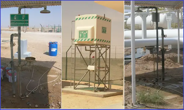
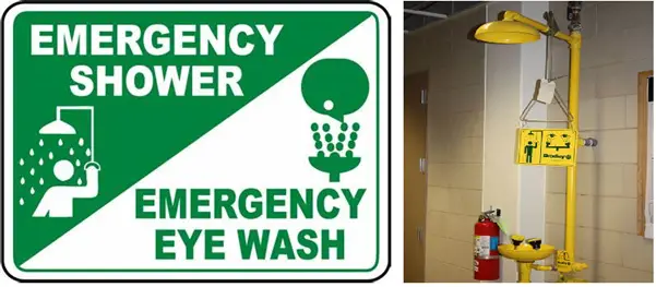
Fig.1: Typical Emergency Shower and Eye Wash Station
Eyewash Stations
Eyewash stations are equipment that can supply adequate fluid to rinse both eyes for a 15-minute duration. The velocity of the flow has to be low enough so that the user can comfortably hold his eyes open. These equipment are installed in areas where impairment of the eye tissue is likely but the possibility of full-body exposure is minimal. Generally, These devices are produced to deliver a minimum 3.0 GPM stream of fluid targeting the ocular cavity, eyes, and face. To provide a gentler rinse, Some fixtures divert the central stream of fluid into several smaller streams or droplets while others provide a directed stream of water to the eye cavities. Similar to Safety Showers, eyewash equipment can also be grouped into two categories:
Plumbed Eyewash Station Unit
They are installed in a fixed position to supply the flushing fluid of adequate volume and pressure complying with the manufacturer’s specifications. The eyewash nozzles must be protected with integrated covers from airborne contaminants.
Self-contained Eyewash Station Unit
They contain a large volume reservoir of flushing fluid within the unit. They can be permanently fixed in place or portable units designed to be easily moved from one location to another.
Safety Shower and Eyewash Station combination
Where there is a risk of exposure to the body, eye, and facial together, Emergency shower and eyewash combination units are typically considered.
Sometimes, Some additional supplemental elements are used in different plants. These are Personal Wash Units, Drench Hoses, Primary Emergency Fixtures, Backflow Preventers, Dust Covers, Foot Controls, Freeze Protection Units, Modesty Curtains, etc.
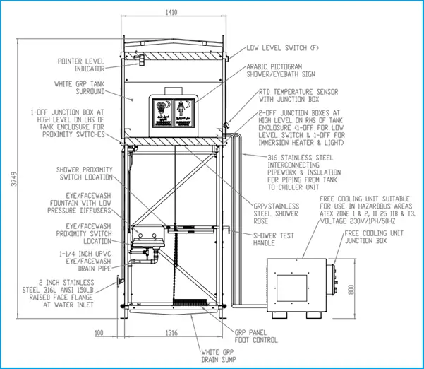
Fig. 2: Sample GA drawing of a combination eyewash and safety shower unit
Other types of safety shower and eye wash stations that the ANSI standard refers to are:
Personal eyewash
Eye/Face wash, and
Hand-held drench hose
Radioactive or highly toxic materials may require a total decontamination shower. These are booth-type showers with numerous spray nozzles. Such units may be combined with central overhead sprayers. A complete safety station combines the eye/face wash fountain with a drench shower. A very useful addition to an eyewash fountain is a face spray ring that sprays the face gently to remove contaminants.
Plant layout, Installation, and Maintenance Considerations for Safety Shower and Eyewash Station
Safety shower & eyewash stations shall be designed as per ISEA/ANSI Z358.1. and they shall comply with minimum requirements as per DEP 80.47.10.32.
The Safety Shower station shall be a foot-operated type and the eyewash station shall be hand operated type.
Both Units should be fitted with appropriate lighting.
An overhead tank that stores the flushing fluid should have a visual level indicator.
The safety shower and eyewash skid shall be insulated to maintain the temperature of supplied potable water between 150 C and 360 C.
Safety showers shall be provided in areas where flammable products are handled and personnel may be exposed to the product.
Safety showers and eyewash stations shall be positioned not more than 15 m (50 ft) away from the potential hazard and be on the same grade level.
An initial hazard assessment of where safety showers are required shall be made and documented.
For cold climate locations, where the stagnant part of the safety shower water supply line could freeze and block the water supply to the outlet, these sections could be provided with heat tracing.
Except for self-contained stand-alone systems, the overall design should allow for regular line flushing to prevent the build-up of bacteria.
The water supply line should have no unnecessary valves that could accidentally be closed.
If the supply pressure can fluctuate, the water supply to the eyewash shall be provided with a regulating valve.
Effluent from the safety shower should be collected or contained for treatment.
Materials of emergency showers shall be such that they will not corrode in the presence of the flushing fluid. Normally Stainless Steel is used with water as a flushing fluid.
The equipment must withstand exposure to ambient airborne contaminants in the area of installation.
Both types of equipment must be maintained to keep them in proper working condition. Equipment owners should be aware of the maintenance schedules found in the ANSI/ISEA Z358.1. standard.
All equipment must be inspected annually to ensure the device conforms to installation requirements.
The equipment must be on the same level the user is working on. If doors are provided in between the hazard and the fixture, they should swing in the direction of travel.
The path to the station must not be obstructed by other hazards to make the path clear for the injured employee.
The drench shower or eyewash should be placed immediately adjacent to the hazard when highly corrosive chemicals are used.
If there are possibilities to affect multiple workers, fixtures with sufficient quantity should be installed to avoid one worker to wait 15 minutes while another is drenched.
All fixtures should be identified with a highly visible sign (Fig. 3).
Employees (workers) must be trained about the location and proper use of the shower and eyewash stations.
Fig. 3: Sign Indicating Safety shower location
Data Required for Ordering Emergency Shower and Eye Wash Station
While creating the Material Requisition (MR) for Safety Shower & Eye Wash device, a datasheet needs to be prepared with the following data at a minimum:
Unit Description: Separate safety shower and eyewash or combined modular unit.
Design temperature and Pressure: Considering the ambient effect of the region.
Service Fluid: Normally Potable Water
Compatible Piping Specification: Normally SS pipe
Design Standard: ISEA / ANSI Z358.1
End connections: Mostly flanged
Connected pipe size: Normally 2 inch
Drain Outlet connection: Normally 2 inch
Device Material: Mostly Stainless Steel
Overhead tank capacity
Any other consideration
Eye and Face Personal Protective Equipment
In general industry or Construction; almost in any work environment, chemical usage may occur. These chemicals can be in the form of hot or corrosive liquids, vapors, gases, and in some cases solids. Such chemicals normally cause physical or chemical burns to the eyes or skin, eye or skin irritation, and distraction or temporary blindness. Using Eye and Face Personal Protective Equipment can be an effective measure against such environments. Based on chemical types, the following types of Eye and Face Personal Protective Equipment can be used:
For Highly corrosive or toxic by eye or skin absorption liquids, vapors, gases, or airborne particles: Ventilated acid fume hood, full face respirator, or special protective suits.
For Hot, strongly irritative, and/or corrosive liquids, vapors, gases, or airborne particles: Chemical goggles and face shields or special chemical hoods.
For Moderate irritants: Chemical goggles and face shield.
For Slight irritants: Chemical goggles or face shields are used with safety glasses with side shields.