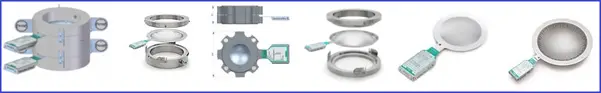
Rupture discs are the second most commonly used pressure relief (protection) devices after safety valves (PSV/PRV) in industrial applications. Rupture Disk is basically a non-reclosing type of pressure relief safety device that protects equipment or system during overpressure situations or potentially damaging vacuum conditions. A rupture disc is also popular as a pressure safety disc, bursting disc, or burst diaphragm. It consists of
- a one-time-use membrane that ruptures at a pre-decided pressure difference between the inlet and outlet of the device (i.e, defined breaking point), either positive or vacuum, thus releasing the pressure
- and a disc holder.
The major objective of the rupture disc (Fig. 1) installation in piping or pipeline systems is to optimally protect and minimize the downtime of the system/plant. As the rupture disc is a one-time-use device. So, it has to be replaced after the burst. Rupture Discs are frequently used for over-pressure protection in chemical, petrochemical, oil & gas, and sanitary applications.
Rupture Disk Materials
Rupture disks can be constructed from any materials that the process fluid permits. Industrial rupture discs are normally constructed from the following materials:
- Carbon Steel
- Stainless Steel
- Graphite
- Hastelloy
- Aluminum
- Nickel Alloys
- Monel
- Tantalum
- Inconel
Rupture disks are widely accepted and used in industry and are normally available from 3 mm to 1200 mm sizes.
Advantages of Rupture Disc over Pressure Safety valve (PSV)
The major advantage of rupture disc compared to electronic, pneumatic, or spring-loaded safety systems are
- the failsafe performance of rupture discs.
- economical.
- high reliability to prevent unnecessary downtime of the system.
- simple design with no moving parts.
- Provide both overpressure protection and depressurizing.
- leak tightness.
- Reduced fugitive emissions – no simmering or leakage prior to bursting.
- react quickly enough to relieve the excess pressure quickly.
- lightweight.
- used for both gas and liquid handling application.
- no additional maintenance cost for each rupture disc per service.
- Greater sensitivity to temperature.
- Protect against rapid pressure rise caused by heat exchanger tube ruptures, runaway reactions, or internal deflagrations.
Disadvantages of Rupture Disc
However, there are a few drawbacks of rupture disks as well. These are
- not possible to test before application.
- can degrade with age or due to corrosion.
- need replacement every time it ruptures. So, a shutdown may be required to refit.
- care to be exercised during installation not to damage the rupture disc.
- improper bolt torque during installation may also affect the disc burst pressure.
- Greater sensitivity to mechanical damage.
Design of Rupture Disc
The Rupture Disc or Rupture Disk consists of one or more flat or domed layers and generally, are round or square in shape. The rupture element of the disc is equipped with breaking points that are normally created by means of lasers. These breaking points can be made of simple cuts or even special geometries. A rupture disk is normally actuated thermally or mechanically. A safety factor should be used regardless of the disk design.
Rupture Disc types
Depending on the applications and suitability, rupture discs can be of different types. They are mostly made of metals or plastics (Inconel, Hastelloy, or Tantalum, plastic liners such as PTFE or FEP.). Domed rupture discs are of two types
- having the dome towards the process (reverse-acting rupture disc) enabling very high operating pressures and operating pressure ratio.
- or having the dome away from the process (forward-acting rupture disc).
- Forward-acting composite disc
- Forward-acting solid metal disc
- Forward-acting scored metal disc
- Graphite disc
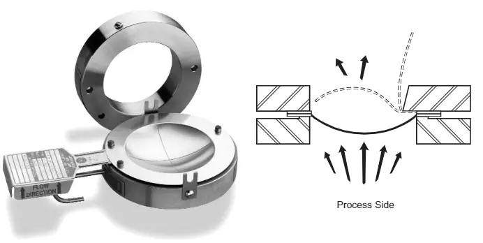
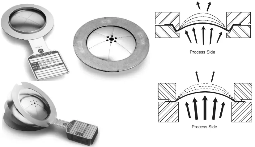
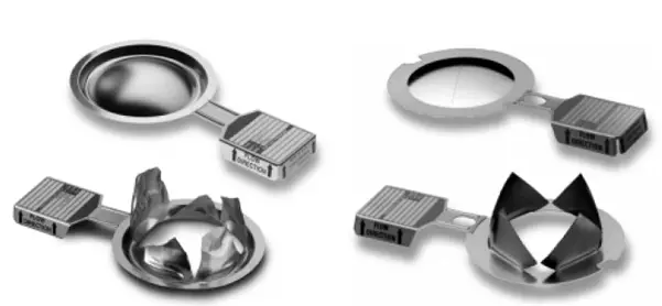
Difference Between Reverse-Acting Rupture Disc and Forward-Acting Rupture Disc
The major differences between the above-mentioned rupture disk types are tabulated below:
| Reverse-Acting Rupture Disc (Fig. 2) | Forward-Acting Rupture Disc (Fig. 3) |
| The convex side of the dome faces the process media | The concave side of the dome faces the process media |
| Functions when the pressure creates an instability in the dome, resulting in reversal, or buckling, of the dome. They are designed to act in compression. | Functions when the weakest portion of the disc exceeds its tensile strength. They are designed to act in tension. |
| Possess longer cycle life and generated stresses are compressive. Hence, less crack propagation. | lower cycle life due to the generation of tensile stresses that promotes crack propagation. |
| Domes are typically supported on the outlet side to prevent movement of the dome prior to reversal. | Normally not supported. |
| Costly | Comparatively cheaper |
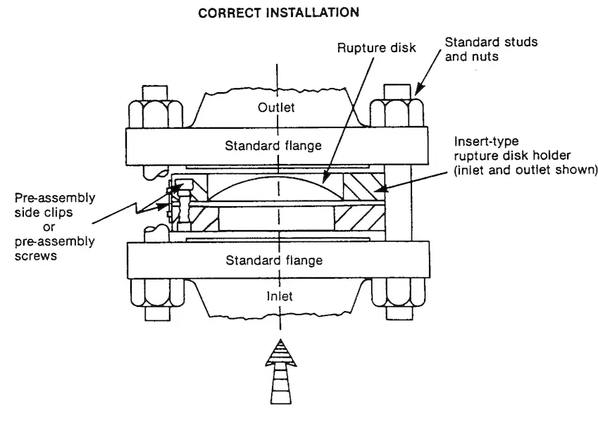
Installation Methodology
A Rupture disc can be installed
- directly between flanges, or
- inserted into a rupture disc holder, which is then mounted between flanges.
Refer to Fig. 4 below which shows one of the standard rupture disc installations.
How do you select a Rupture Disc?
Rupture discs are not standardized products. hence, various parameters need to be considered for the optimal selection of the right device. Some of those parameters for the proper selection of a rupture disc are:
- Line operating parameters.
- Pipe size (The diameter of the rupture discs is specified matching the diameter of pipes or flanges as the nominal pipe size DN or NPS (Nominal Pipe Size).
- Burst or set pressure (The pressure at which the rupture disc opens. It is selected in such a manner, that the rupture disc opens before there is any system damage. It is normally, above the working pressure during normal operation and below the maximum allowable working pressure) and corresponding temperature.
- Burst tolerance: Defines the tolerance around the defined burst/set pressure at which the rupture disc opens. For example, If a ruptured disc has a burst tolerance of +/-10%, and the defined burst pressure is 10 bar, the rupture disc will open between 9 bar and 11 bar.
- Permissible overpressure or vacuum pressure
- Process medium
- Vacuum resistance
- Pulsation
- Necessary vent area, or required flow rate
- Phase Application: Gas-only rupture discs should be used for gaseous medium only.
- Rupture Disc Operating ratio: This is the pressure at which the rupture disk can be operated with prolonged service life. Depending on the construction method and materials used, Rupture disks have a maximum operating ratio of about 50 to 95%. So, rupture disk selection must consider this ratio for proper working.
Components of a Rupture Disc
The main components of a rupture disk are:
- Rupture Disks
- Rupture Disc Holders
- Alarm system to transfer the signal for rupture disc opening
- Heat Shield
- Baffle Plates
Sizing a Rupture Disc
Rupture Disc Sizing for a particular application is done following the standard methodologies described in ASME Section VIII Div. 1, API RP520, API RP 521, and Crane TP-410. Three basic methodologies are followed for sizing rupture disc devices. They are:
- Coefficient of Discharge Method (Kd)
- Resistance to Flow Method (Kr) and
- Combination Capacity Method
Co-efficient of Discharge Method of Rupture Disc Sizing
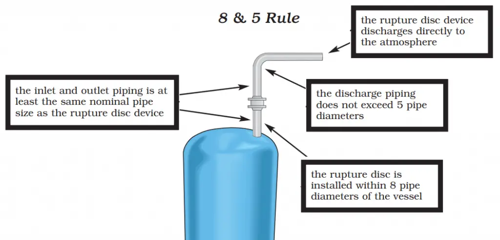
In the coefficient of discharge model, The rupture disk is considered as a relief valve, and the flow area is estimated using relief valve formulas with a fixed coefficient of discharge, “Kd” of 0.62. In order to use this method for rupture disc sizing, the following four conditions must be met:
- The rupture disk has to be installed within 8 pipe diameters of the equipment or the overpressure source.
- The rupture disk discharge pipe should be limited to 5 pipe diameters.
- The rupture disk discharge should be directed to the atmosphere.
- The inlet and outlet piping is at least the same nominal pipe size as the rupture disk.
This is popularly known as the “8 and 5 rule”. A typical sketch of the “8 & 5” rule for rupture disc sizing is provided in fig. 5 below:
The flow area calculated is known as the Minimum Net Flow Area (MNFA). This is the rupture disk’s minimum cross-sectional area needed to meet the required flow. The rupture disc manufacturer publishes the actual Net Flow Area (NFA) for each model and size. For the selected rupture disk the NFA should be greater than or equal to MNFA.
Resistance to Flow Method of Rupture Disc Sizing
The Resistance to Flow Method analyzes the flow capacity of the relief piping and accounts for the frictional losses of the relief piping and all components. Such losses normally include nozzle entrances and exits, elbows, tees, reducers, valves, and the rupture disk. The rupture disk is also considered a piping component and its contribution to the overall frictional loss is determined.
A factor Kr that represents the velocity head loss due to the rupture disc device is determined experimentally in flow laboratories by the manufacturer for their line of products and is certified per ASME Section VIII, Division 13. This Kr accounts for the holder and the bursting characteristics of the disk. API RP521 recommends using a Kr of 1.5. However, ASME Section VIII, Division 13 states that a Kr of 2.4 shall be used. ASME PTC25 provides standardized test methods to measure the Kr of rupture disc devices. By quantifying this performance characteristic, rupture disc devices may be selected.
Where do you use a Rupture Disc?
The following picture (Fig. 6) below shows three main cases of rupture disc applications.
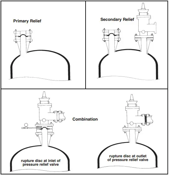
Rupture Disc as Primary Relief
A rupture disc can be used as another pressure relief device to protect a vessel of the piping system from overpressure. In the following cases, they can be preferred as a primary relief option over pressure relief devices:
- When the pressure rise is so large and rapid that extremely fast-acting is required to prevent catastrophic failure. A relief valve (PSV/PRV) can still be installed in parallel to protect against other relieving scenarios.
- When the relieving fluids may impede the proper operation of the pressure relief valve.
- The use of a ruptured disc as primary relief is attractive if the relieving fluids are non-toxic, non-hazardous, and the system stop and the loss of fluids is not an issue.
- When the vessel has no permanent supply connection, and to protect the vessel against exposure to fire or other sources of heat. This is usually the case with storage vessels for non-refrigerated liquefied compressible gases at ambient temperatures.
Rupture Disc as Secondary Relief Device
- As stated earlier, rupture discs and pressure relief valves can be used in parallel. In such a configuration, the design considers a double jeopardy scenario and gives protection with both the vessel overpressure and the pressure relief valve failure.
- If the process involves exothermic reactions where abnormally high and uncontrollable pressure conditions arise, parallel installation of a Rupture disc and PRV is recommended.
Combination of a Rupture Disc and Pressure Relief Valve
The combined use of a ruptured disc along with pressure relief valves is becoming more popular within industries nowadays. There are two potential possibilities:
- rupture disc upstream (inlet) of the relief valve.
- rupture disc downstream (outlet) of the relief valve.
Rupture disc at the inlet of Pressure Relief Valve
The process benefits of installing a Rupture disc upstream of PRV/PSV are the following:
- It ensures positive sealing of the system.
- It protects the PSV/PRV from fluids containing solids, that may plug/damage the valve.
- It provides protection of the valve from corrosion and thus reduces valve maintenance.
- It allows in-situ testing and calibration of the safety valve.
Rupture Disc at the outlet of the Pressure Relief Valve
A rupture disc can also be installed on the downstream side of the pressure relief valve for the purpose of protecting the valve from the atmospheric downstream fluids. If the relief fluids are vented in the common header vented media can result in either corrosion or polymerization. In such cases, the Rupture disc would isolate the vented media from the relief valve.
Rupture discs can also be used upstream as well as downstream of Pressure relief devices.
Few more Resources for you..
Routing Of Flare And Relief Valve Piping: An article
Various types of pressure relieving devices required for individual protection of pressure vessels in process plants
Modeling Relief Valve (Pressure Safety Valve) Thrust force
Stress Analysis of PSV connected Piping Systems Using Caesar II