Injection and mixing points are locations used frequently in refineries, petrochemical, and power plants and carry a potential risk of increased degradation rate compared to the mainline due to the changes in temperature, pH, phase changes, and the concentration of corrosive species. Because of that, dedicated publications and literature addressed the requirements for the design and inspection of the mixing areas
What is an Injection Point?
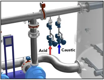
Injection Point: Injection Points are locations where chemicals, or process additives, are introduced into a process stream. Corrosion inhibitors, desalter demulsifiers, neutralizers, process antifoulants, oxygen, hydrogen scavengers, caustic, and water washes are most often considered to be requiring special attention during injection point design. [1]
What is a Mixing Point?
Mix Points: Mix points or Mixing Points are points of joining of process streams of differing composition and/or temperature where additional design attention, operating limits, and/or process monitoring are utilized to avoid damage mechanisms (e.g., corrosion).
Design Precautions of Injection Devices
Injection of corrosive chemicals like caustic, and sulfuric acid can cause serious corrosion issues and it is best to be avoided, injection facilities should be designed to allow proper mixing and dilution of the injected chemical in order to avoid the concentration of chemicals on hot metal surfaces. [4]
Material Selection for Mixing Zone
While selecting materials for the mixing zone, consideration shall be made for local erosion, corrosion-erosion, and corrosion rates influenced by flow regime and turbulence. High corrosion-resistant alloys or internally lined injection facilities can be used based on the injected chemical, mixing facility configuration, and operating temperature.
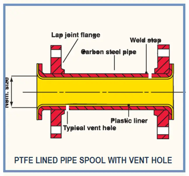
Each lined pipe and fitting shall be provided with a venting system that will release any annular pressure between the polymer liner and the host metallic component.
NOTE —Venting is not required with PVDF, PP, ETFE, or PVDC liners.
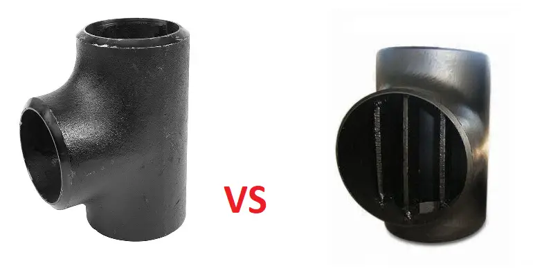
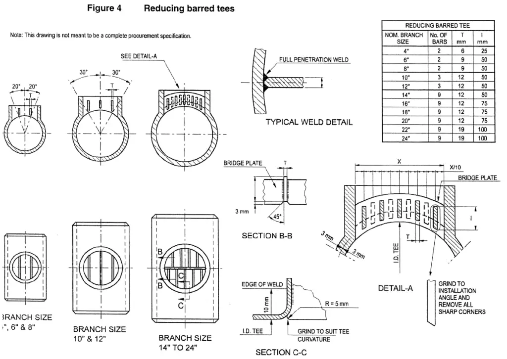
Injection devices
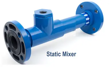
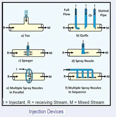
Injection device designs should include the design of piping tees, spray nozzles, quills, and/or static mixers.
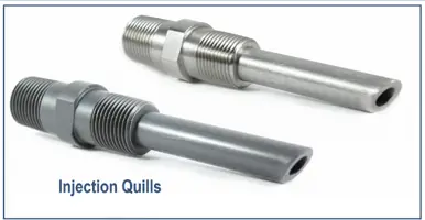
Design Considerations for Quills
- Quills should discharge co-currently into the center of the receiving stream to enhance dispersion and prevent contact of undiluted injectant with the pipe wall.
- Quill designs shall include flow calculations to determine the natural frequency and whether fatigue is an issue.
- Quills with beveled ends should be considered, as they promote better dispersion and mitigate potential corrosion or fouling caused by concentrating chemical injectant at the pressure boundary.
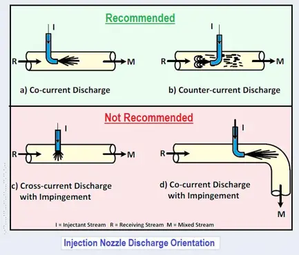
Considerations for Spray Nozzles
- Spray nozzles should be considered for injecting liquids into gas streams or when the injectant is required to coat/wet the pipe wall. Spray nozzles are used to disperse the injectant stream.
- The co-current injection is suggested when wetting is the desired result.
- Cross-flow injection should be avoided because it results in impingement on the pressure boundary wall. Impingement can also occur when the injection is too close to a change in direction.
Injection into Vessels or Tanks
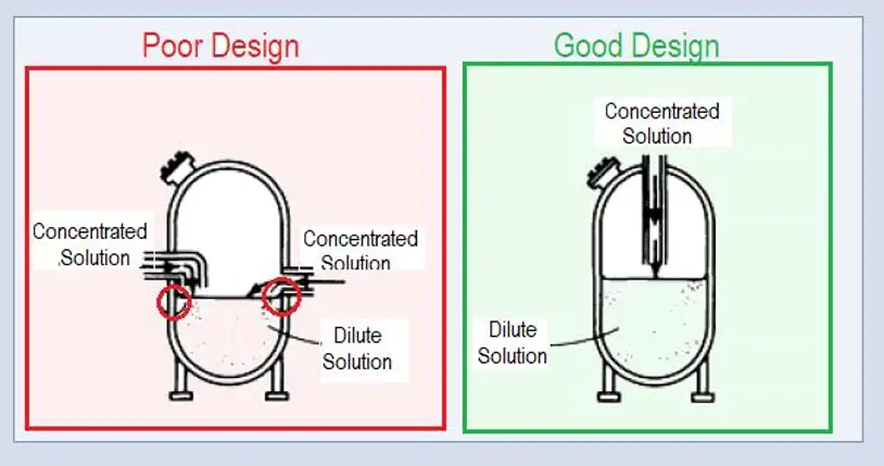
For injection into pressure vessels or tanks, designs that tend to concentrate corrosive media in a small area should be avoided. For example, tank inlets should be designed in such a way that the concentrated solutions are mixed and diluted when they are introduced. Otherwise, excessive corrosion can be caused by localized pockets of concentrated solutions. The poor design causes concentration and uneven mixing of incoming chemicals along the vessel wall (circled areas). Good design allows concentrated solutions to mix away from vessel walls. [3]
Temperature Difference
High-temperature differences between the injected stream can the mainstream can cause thermal shock, this shall be considered in the design of the injection nozzle to avoid direct contact of the injected stream with the metallic wall of the mainstream. Another approach can be by changing the temperature of the injected stream (heating or cooling) to approach the temperature of the mainstream.
Operational Considerations
Plant operators should understand the potential risk of the improper use of the injection points. For the operating schemes where the flow of the mainstream is not continuous, the chemical injection shall be stopped while the mainstream is flowing, then the mainstream can be stopped. And for starting chemical injection, the operator shall ensure that the mainstream is flowing before starting the chemical injection.
This can be best achieved by design through the application of interlock. Otherwise, operating procedures with a checklist shall be developed with proper protocol to avoid mistakes.
Inspection Considerations
Injection points are sometimes subject to accelerated or localized corrosion. Those susceptible should be treated as separate inspection circuits, and need to be inspected thoroughly on a regular schedule. [2]
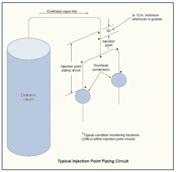
At the time of scheduled periodic inspections, extensive inspection should be applied to an area beginning 300 mm upstream of the injection nozzle and continuing for at least 10 pipe diameters downstream of the injection point. [2]
In the case of the use of plastic-lined pipes equipped with vent holes, in the event of a liner failure the steel housing is likely to corrode evenly within the pipe and cause a catastrophic and unannounced failure. Vent holes shall not be Plugged. If the line is insulated, extend the vent out of the cladding and include the check of leaks through the vent holes in the periodical inspection and patrolling checklist.
References
- [1] NACE SP0114-2014: Refinery Injection and Process Mix Points
- [2] API 570: Piping Inspection Code: In-service Inspection, Rating, Repair, and Alteration of Piping Systems
- [3] ASM Metals Handbook, Volume 13 – Corrosion
- [4] API 571, Damage Mechanisms Affecting Fixed Equipment in the Refining Industry
- [5] [ASTM F1545 Standard Specification for Plastic-Lined Ferrous Metal Pipe, Fittings, and Flanges]