While stress analysis and supporting considerations it is always a better engineering practice to provide line stops or axial stops or pipe anchors at the neutral point of the straight portion of the piping. It is believed that at the neutral point, thermal movement is zero and frictional resistance equalizes from both sides of the piping system. In such a scenario, the frictional forces cancel out as forces are positive on one side and negative on the other. Also as there is no thermal movement, there will be zero axial loads due to the temperature effect. So, the software will show zero anchor loads in such locations.
Example of Zero Anchor Loads
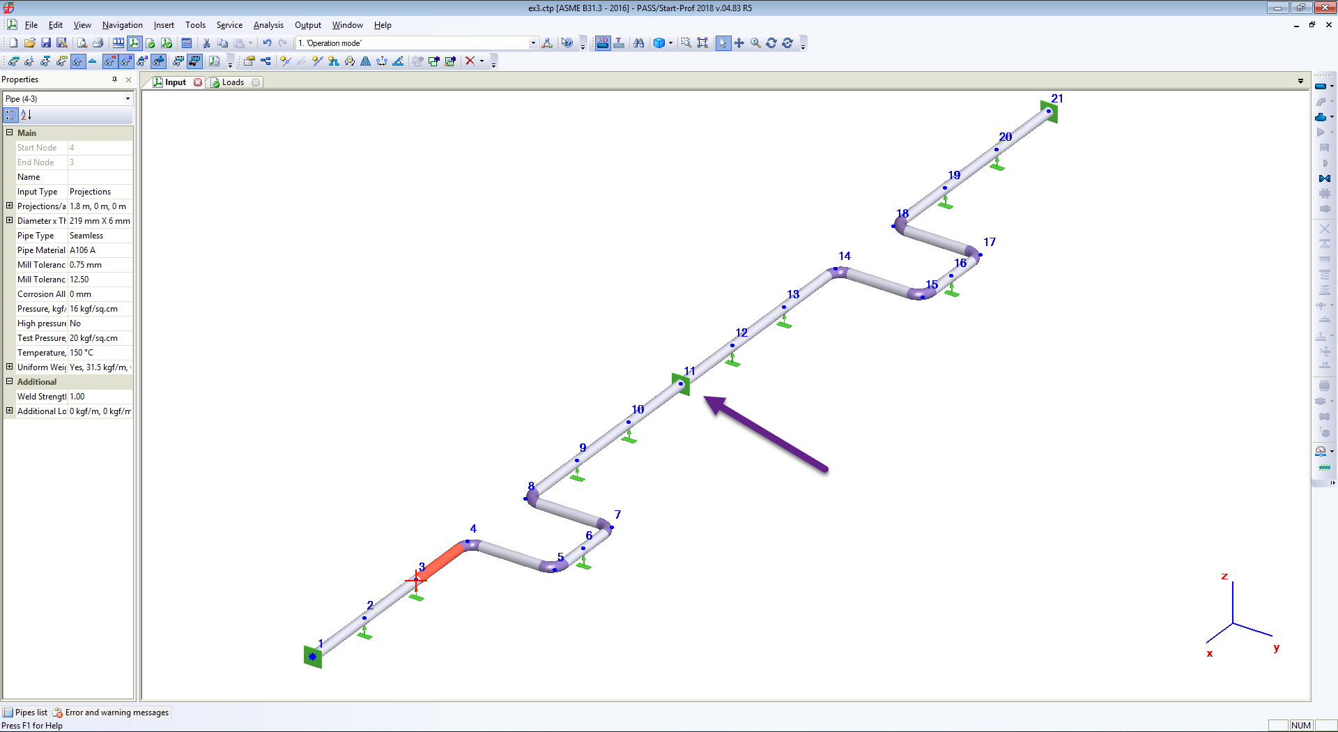
For example, In the following symmetric system with two U-shape loops, as shown in Fig. 1, The leg length on both sides of the intermediate anchor is equal. Thus the intermediate anchor node 11 becomes a neutral point.
Fig. 1: Symmetrical piping system with Intermediate Anchor
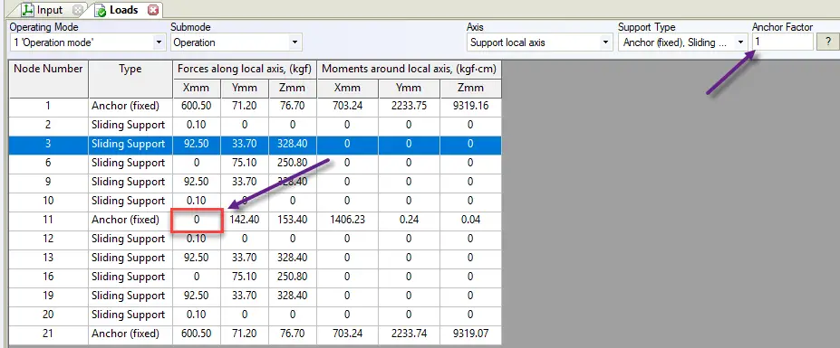
As can be seen in Fig. 2, The load along the pipe in an intermediate anchor (node 11) will be zero.
Fig. 2: Zero Anchor Load for the System shown in Fig. 1
In reality, the piping heating up can be uneven, the friction forces can be different on the left and right parts of the piping, piping design can’t be ideal. Therefore, the real load on the anchor will not be zero.
How to Avoid Zero Anchor Loads?
To avoid such a situation the Anchor Factor “k” is used in piping stress engineering practice. The following method can be manually used in any pipe stress analysis software. In PASS/START-PROF piping stress analysis software this is a built-in function.
If loads from pipes to the left and right of the support (N1 and N2) are in the same direction, they are combined as N1+N2
If loads N1 and N2 are in different directions, the lower values are multiplied by k and then combined as N1+N2*k (|N2|<|N1|)
If the support is on an end node, factor k is not used
Factor k is applied only for loads in the horizontal plane: axial force, lateral force, and horizontal moment.
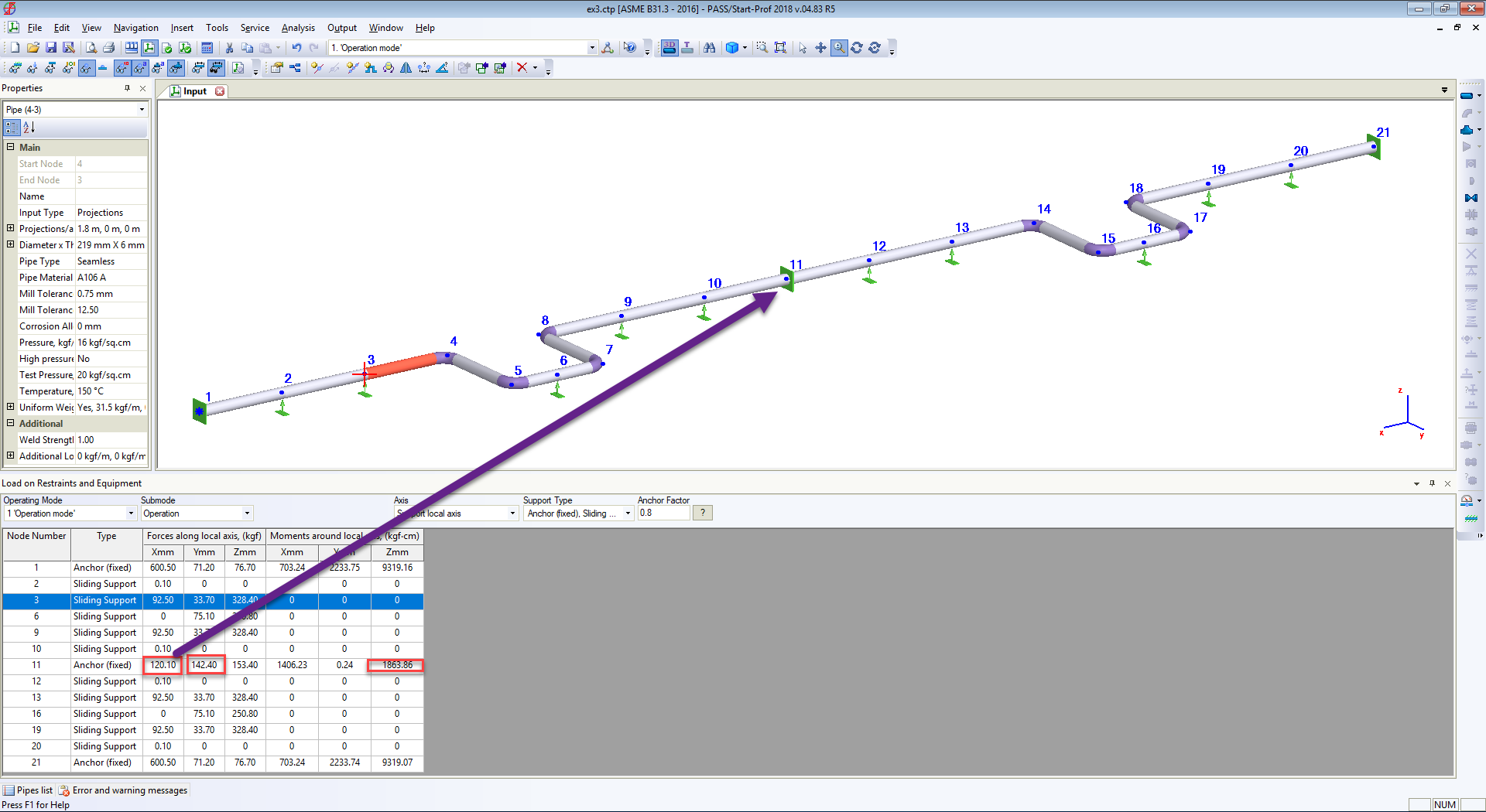
The common value, that is recommended by some piping stress analysis codes is k=0.8. If we use a 0.8 value the result will be as shown in Fig. 3. and Fig. 4.
Fig. 3: Actual Anchor Load in Axial Direction
Fig. 4: Intermediate Anchor with Actual Anchor Load in Start-Prof
The following training video shows how to create this model. It takes 2 minutes
Piping support plays a very crucial role in the proper functioning of piping systems. Pipe support carries the pipe weight with contents. To maintain the integrity of the piping system, A pipe must be supported following a proper pipe support span. Pipe support engineering is very critical for the success of any project as an accurate and judicious selection of piping support is required. Pipes as irregular space frames are not self-supporting so must be supported. Piping Loads are transmitted from pipe to supporting structures with the help of pipe supports. Proper pipe support knowledge during the layout stage is advantageous.
The piping system is a major part of any hydrocarbon industry. Proper pipe support knowledge during the layout stage is advantageous. Piping Loads generated due to Weight, Pressure, Temperature, or Occasional Events have to be transmitted from pipe to supporting structures with the help of appropriate pipe supports.
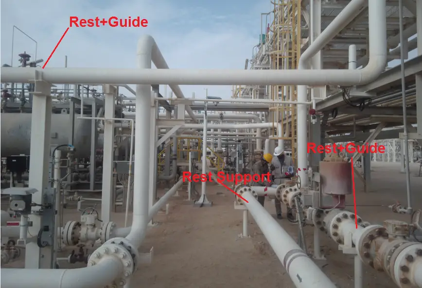
Difference Between Pipe Support and Pipe Restraint
The term “Restraints” is invariably used for pipe supports. However, there is little difference between pipe support and restraint. Pipe supports are used to support the piping system by carrying the vertical load whereas pipe restraints limit the movements of the pipe so take care of the horizontal loads. So from the definition, Simple Rest is pipe support but Guide and line stops are pipe restraints. Normally, All pipe restraints come in combination with piping supports. Pipe support and restraints, combined can be said pipe support systems. Henceforth, the term pipe support refers to the pipe support system.
Purpose or Functions of Piping Support
The various functions that pipe support serves are as follows:
For the proper working of the piping system, it has to be supported properly. The major purpose of pipe supports can be elaborated as follows:
Piping Supports for Carrying Weights
Pipe Supports are required to support the line during all conditions i.e. during operation as well as during testing. In the case of the vapor line, this difference will be very large due to hydro testing. Supports should be designed for this load (unless otherwise decided in the project). Sometimes the line is capable of having a longer span but the load coming on the support may be very large (especially with large-diameter pipelines). Then to distribute the load uniformly, the number of supports should be provided with a smaller span.
Notes:
It may be noted that during testing conditions there is no thermal load.
Piping Supports to Take the ‘Thermal or Expansion Load’
Whenever thermal expansion is restricted by pipe supports, it introduces additional load on the support. Support restraints must be designed to take this load in addition to all other loads.
Pipe Supports transfer the Occasional Earth Quake Loads
The earthquake is normally associated with horizontal acceleration of the order of 1 to 3 m/sec2. This is around 10% to 30% of the gravitational acceleration and introduces a horizontal force of about 10 to 30% of the vertical load (or supported mass). While designing pipe support, this should be taken care of.
When the pipe is subjected to moving machinery, pulsating flow, or very high-velocity flow, the pipe may start vibrating vigorously and ultimately may fail, particularly if the span is large. To avoid this it may be required to introduce additional supports at a smaller span apart from other requirements. It may not take axial load but must control lateral movements.
Carry the ‘Occasional Wind Load’:
Wind introduces lateral load on the line. This load is considerable, especially on large diameter pipes, and increases as line size is increased. This load tends to sway the line from its normal position and the line must be guided properly against it to avoid any kind of malfunction. In the case of large-diameter overhead lines, supported by tall support extended from the floor, wind load introduces large bending moments and should be considered critically.
Support the System during the ‘Transient Period of Plant & Standby’
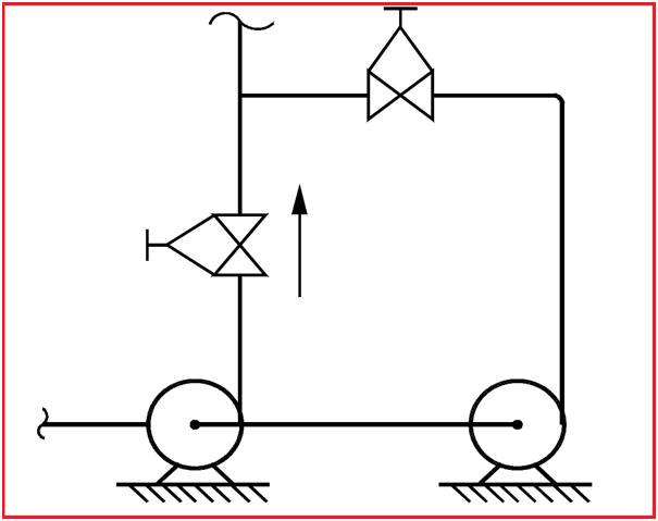
Transient Condition: Transient condition refers to the start-up or shutdown condition in which one piece of equipment may get heated up faster and the other one gets heated slower. Due to this the expansion of one piece of equipment that in normal operation will get nullified, may not get nullified, and exert a thermal load on supports.
Fig. 2: Operating- Standby Condition
The standby condition is also similar. If there are two pumps, one being standby and both connected in parallel (as shown), the design and operating temperature of both connections will be the same. But the expansion of two parallel legs will not be nullified because at a time only one leg will be hot, and the other will be cold.
Noise due to pulsating flow can be reduced by using a silencer in the line. Still, if it is not below an acceptable level acoustic enclosure may be used. Piping Insulation over the line also helps in reducing the noise.
Support the System during ‘Maintenance Conditions’
When for maintenance certain equipment or components like the valve are taken out, the remaining system should not be left out unsupported.
Fig. 3: Figure showing support addition during maintenance activities
Referring to FIG-3, support ‘S1’ will be sufficient but when valve ‘V1’ is taken out for maintenance there will not be any support for the vertical leg. Therefore second support ‘S2’ may be required to take care of such conditions.
Piping Support for ‘Shutdown Conditions’
In shutdown conditions, all equipment may not be in the same condition as in operating conditions. For example, refer to the pump discharge line in Fig-4, Point A is resting, Point B & C are spring supports and Point D is the pump discharge nozzle. The springs are, designed based on weights considering the weight of fluid as well as pipeline and thermal movements. But during shutdown conditions, the fluid may be drained and the pipe becomes lighter. Hence, the spring will give an upward reaction and shall load the nozzle ‘D’ beyond the permissible limit.
Fig. 4: Use of Limit elements in spring during shut-down
In this case, a limit stop is used which will not allow Point C to move up above the horizontal level. (However, it will allow downward movement during operating conditions).
Use of Pipe Support for Erection Conditions
Erection conditions can be different than the operating conditions which should be considered while designing supports.
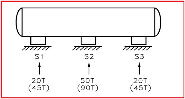
For example, for normal operation, a long vessel supported by three supports, S1, S2 & S3 is shown in FIG-5. If support S2 is higher then all load will act at S2 only. During an erection, if the level of S2 is lower then the entire load will be divided into two supports S1, and S3 only. Therefore the foundation of S1, S2 & S3 should be capable of taking such conditions.
Fig. 5: Vessel supported at three supports.
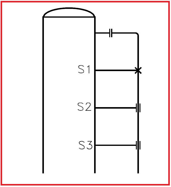
A pipeline supported by S1, S2 & S3 taken from the vessel is shown in above FIG – 6. During operation, there will be no weight at S2 & S3 (as it is the only guide), but wind conditions will be there. Loads due to such conditions must be considered while designing the supports.
Fig. 6: Pipe supported from vessel cleats/clips.
Codes and Standards for Piping Support Design
The following codes and standards are used for piping support design.
ASME B31.3: Process Piping Code ASME B31.3 is the base code for pipe-supporting requirements.
MSS-SP-58– Establishes the material, design, and inspection criteria to be used in the manufacturing of standard pipe supports. (USA)
MSS-SP-69- Provides recommendations for the selection and application of pipe supports. (USA)
MSS-SP-89- Provides recommendations for the fabrication and installation of pipe supports. (USA)
MSS SP-89: Provides fabrication and installation practices for Pipe Hangers and Supports.
MSS SP-90: Explains guidelines on the terminologies for Pipe Hangers and Supports.
MSS SP-77: Provides guidelines for Pipe Support Contractual Relationships.
BS-3974- Specification of pipe supports 1, 2, 3. (UK)
VGB-R-510 L- Standard supports guidelines. (Germany)
RCC-M- Specifications for pipe supports. (France)
MITI 501- Technical regulations (Japan)
Piping Support Design and Selection
The complex requirements of today’s piping support design are reliable functioning, maintenance-free operation, economical and easy installations, quick delivery of components, and low unit prices.
Major Criteria (Parameters) governing the pipe support hardware selection are
Pipe Support function,
Pipe Material for construction
The magnitude of expected operational and occasional load,
1. Types of Piping Supports based on the attachment with Pipes
Primary Piping Support
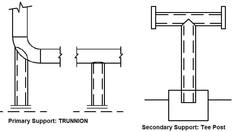
Pipe Supports that are directly attached to the pipe are called Primary pipe Supports. For example, Shoe support, Clamp Support, Guide Support, Line Stop Support, Trunnion Support, etc. The design and selection of primary pipe support (Fig. 1) is the responsibility of the piping team.
Secondary Piping Support
Pipe supports that are not directly attached to the pipe are called secondary piping supports. Support Brackets, Secondary Steel members on which pipe or primary supports rest, Tee Posts, Goal Posts, sleepers, racks, etc. are examples of secondary pipe supports. The design and selection of secondary pipe supports (Fig. 7) are the responsibility of the civil team.
Fig. 7: Primary vs. Secondary Support
2. Types of Pipe Supports based on Hardware Rigidity
Rigid Supports
Rigid supports provide rigidity at least in any one direction to restrict the pipe displacement in those direction(s) without any flexibility in that direction. Rigid pipe supports can serve as a Rest, Guide, Line Stop, or any combination of these. A fixed anchor is also a rigid support that provides rigidity in all six degrees of freedom. Typical examples of rigid supports are pipe shoe support, Rigid Strut Support, Trunnion Support, Saddle Support, etc.
Resilient Supports
Resilient or elastic supports use an elastic member for carrying pipe load and allow the pipe movement in the desired direction. Spring Hanger Supports which use a compression spring are known as Resilient Supports.
Adjustable Support
An adjustable support (Fig. 9) can be adjusted at the site during plant operation. These supports are normally provided for pipe and equipment alignment purposes. The first support from a pump suction and discharge pipe is provided with an adjustable pipe support. Sometimes the first support from a storage tank pipe system is also provided as adjustable support to adjust the support length in case of tank settlement.
3. Pipe Support Types Based on Piping Insulation
For hot insulated pipes, piping shoe/saddle supports are used for support. For cold insulated pipes, cold shoes (cradles) are used while supporting the pipes. For piping systems having acoustic insulation, special arrangements are made to isolate the vibrating pipe and supporting structure.
4. Types of Pipe Supports based on Weldng Requirements
Based on welding requirements, the supports may be welded or clamped. Welded pipe supports (shoe supports) are used on piping systems where welding is permitted. However, for certain piping systems, where welding is difficult or not allowed, clamped types of piping shoe supports are used.
5. Piping Supports based on the Function of the Support
Depending on the pipe support function, piping supports may be known as Rest, Guide, Hold Down, Anchor, Axial Stop, etc. These mentioned terms are defined in the pipe support terminology section.
6. Piping Supports Based on Pipe Orientation
Again, pipe supports can be differentiated based on the orientation of the pipe run. The support types and functions may be different when using the same support in a piping system of vertical or horizontal orientation. For example, a hold-down and guide support in a horizontal pipe will act as a hold-down and guide but the same in a vertical pipe may act as an all-around guide.
Piping Support Rules/Guide for Optimization
The following points need to be followed for optimized pipe support.
Group pipelines so as to minimize the number of structures needed solely to pipe supports.
Route lines close to the possible point of supports ( i.e. grade or structure which is provided for other purposes.)
Supports or braces are to be located at or near neutral points. (thermal null points)
Supports to be located as near as possible to concentrated loads such as valves, flanges, heavy actuators, etc.
Piping susceptible to vibration such as compressor connected lines to be supported independently. The use of hold-down or similar supports offers resistance to motion and provides some damping capacity to be used rather than hanging-type supports.
Piping connected to the top of the vessel to be advantageously supported from the vessel to minimize relative movement between supports and piping.
Always maintain the distance between supports as per the project specification recommended support span table. ( it is applicable to straight-run pipe length only.) When a change of direction in a horizontal plane occurs, it is suggested that the spacing be limited to ¾ times the standard pipe span.
Sufficient space to be provided to facilitate support assembly installation, inspection, and maintenance.
Fig. 8: Typical Piping Supports in Operating Plant
Piping Support Terminologies and Definitions
Brace or Bracing Support- A device primarily intended to resist displacement of piping due to forces other than thermal expansion and gravity.
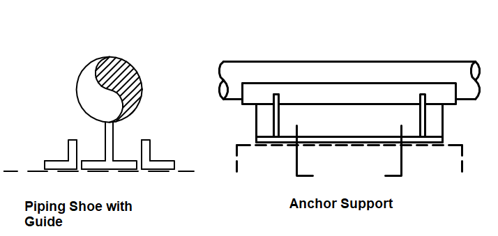
Anchor Support or Fixed Support- A rigid restraint providing substantially full fixation is termed an anchor. Anchor support restricts all six degrees of freedom (three translational and three rotational) and does not allow the pipe to move in any direction. Normally Full-Welded or Bolted supports are called anchor supports. Full Anchor supports (Fig. 10) are rarely used in piping systems.
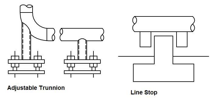
Stop- A device that permits rotation but prevents translatory movements of piping. A line stop or axial stop (Fig. 9) prevents pipe movement in the axial direction of the pipe. It is also known as a stopper.
Guide- A device that prevents the rotation of one or more axes is called a guide (Fig. 10). Guide supports (Fig. 8) prevent Lateral pipe movements.
Hold Down Support- A device that holds the pipe in position disallowing vertical upward movement or allowing decided upward movement. Hold-down supports prevent pipe disengagement from the Support structure.
Hanger- A support by which piping is suspended from a structure that functions by carrying the piping load in tension.
Rest Support or Sliding support- A device that is provided below piping to take gravity loads, offering no resistance other than frictional to horizontal motion. Rest supports (Fig. 8) do not allow the pipe to sag or move downward.
Damping element- A device that increases the damping of a system offering high resistance against rapid displacement, caused by dynamic loading while permitting essentially free movement.
Dummy Leg – Basically an extension pipe welded to an elbow, to provide support either as a resting, anchor, etc.
Fig. 9: Line Stop and Adjustable Trunnion Support
Popular Types of Piping Supports
The following types of piping supports are most popular in the oil and gas, and petrochemical industry.
Typically piping is supported at regular intervals on steel supports embedded in concrete foundation or directly on the steel structure. The distance between supports is the supporting span.
The basis for the calculation of the maximum support span
There are three main factors that affect the support span.
Supporting Criteria for Critical Lines: The support location is usually decided by piping designers. The type of support is decided by stress engineers. Primary attachments and secondary supports are selected by the designers whereas Line stop/Guide supports and gaps are informed by stress engineers.
Supporting non-critical lines
Senior designer to decide on support type and location based on
Support span
Guide span
Concentrated loads e.g. valves, instruments, etc
For the Long piping legs, the stress engineer is to be consulted
Supporting Insulated Pipes
No direct resting, pipe shoe to be provided
Minimum clearance between the insulation and the supporting structure shall be at least 50 mm.
Supporting of Non- Insulated Pipes
Directly rested except following
Pipes with sizes larger than DN 600
CS pipes with less than SCH 20
SS pipes with less than SCH 10S
The pipe that requires a slope
Dissimilar material to avoid galvanic corrosion
The pipe is to be supported on a pipe shoe to avoid damage to the pipe wall
Supports to be located on the upper half of the portion (i.e. above C.G. of pipe)
The vertical guide spacing is normally lower than the horizontal guide spacing
Clamped supports with weld-on shear lugs to avoid the pipe slipping under the clamp
Special Pipe Supports or SPS
The pipe supports that do not fall in the above category are called special pipe supports. Various kinds of special pipes are required for critical lines. The design is normally slightly complicated and a separate drawing is prepared for each special pipe support. For example
Spring hanger along with Guide
Hanger along with guide and line stop
Normal primary support requiring additional strengthening due to increased load, etc
The drawing is normally prepared by the pipe stress or pipe support engineer and checked by a civil engineer to ascertain the structural member load-carrying capability.
Differences Between Piping Support and Pipeline Supports
The main function of supports in both piping and pipeline systems is usually the same. However, there are certain distinct differences between the piping support and pipeline supports that are specified in the table below:
Feature/Aspect
Piping Supports
Pipeline Supports
Scale and Length
Used within facilities, handling shorter lengths.
Used for long-distance pipelines (hundreds or thousands of miles).
Environment
Controlled environments like plants and refineries.
Varied and often harsh environmental conditions (deserts, mountains, etc.)
Design Considerations
Managing weight, thermal expansion, and vibrations of pipes within a facility
Addressing large-scale thermal expansion, ground movement, and environmental factors over long distances.
Common Support Types
Hangers, saddles, guides, anchors, spring hangers, rigid hangers, and various complex arrangements.
Pipeline supports are usually simpler as compared to piping supports. Typical examples are sleeper supports, anchor blocks, above-ground piers, etc
Operational Context
Industrial facilities, refineries, power plants, processing complexes, etc
Long-distance pipelines, transporting fluids or gases across vast distances.
Support Span/Spacing
Usually less due to high temperature.
The support span in pipelines is comparatively large due to low-temperature applications.
Table 1: Piping Support vs Pipeline Supports
This table provides a clear comparison between piping supports and pipeline supports, highlighting
Online Video Courses on Piping Support
To learn more about piping support design and engineering you can opt for the following video course.
Many of the failures that we experience in the process industry are due to overpressure. Overpressure is the result of unbalance or disruption of normal flows of material and energy. This causes material or energy, or both, to build up in some part of the system. Overheating above the design temperature may also result in overpressure, due to the reduction in allowable stress.
We cannot imagine the oil and gas industry without pressure vessels and these include separators, Knock Out drums, columns, steam drums, etc.
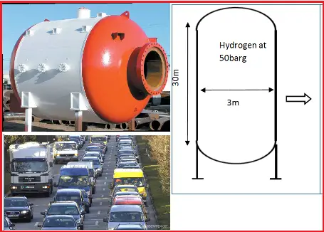
The thermodynamic energy contained in a pressure vessel can be very large.
The energy stored in this pressure vessel operating at 50 barg is 0.5*10^10 NM
This is equivalent to the kinetic energy of 13000 cars of 1000 kg each driving at a speed of 100km/hr
Fig. 1: Pressure Vessel and Impact of Pressure
Effects of Pressure:
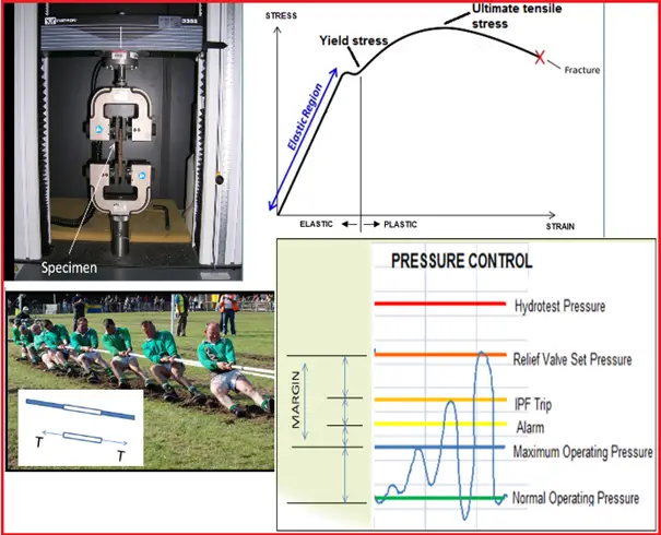
You might have seen or participated in Tug of war or rope pulling where two teams pull on opposite ends of a rope.
In a similar way if we apply tension or stress to a steel specimen by pulling it to different levels the specimen under stress starts to deform and elongate.
The strain is a measurement that gives the change in length of an object divided by the original length
With increasing stress, if we measure corresponding strains, then we can plot a stress-strain curve for that specimen as shown on the right.
Deformation in the elastic region is reversible i.e. Once the forces are no longer applied, the object returns to its original shape.
Plastic deformation is not reversible.
Yield stress is the minimum stress that causes a material to lose its elastic behavior and deforms permanently.
Pressure inside also subjects equipment to stress. If a vessel designed for 3.5 barg pressure is subjected to higher pressures, it may result in catastrophic failure.
Pressure Vessel Codes
Robust Process and Mechanical Design are the fundamental and first barriers to ensuring safe operations.
At the start of the 20th Century, there were numerous incidents related to pressure vessels and manufacturers started to exchange their know-how and experiences. This finally resulted in the nationalized codes on pressurized equipment. Applying a pressure vessel code provides the equipment with sufficient margins against failure under specified temperatures and pressures.
The pressure vessel code allows pressure vessels to be designed, operated, and manufactured along with rules set up by the industry and is widely used by manufacturers and operators.
The main objectives of the pressure vessel codes
Ensure that the vessel will be safe under all foreseeable circumstances.
Define minimum protection requirements
Clearly define the responsibilities of various parties in design and construction
Give requirements for manufacturing and quality control of equipment
Clearly define operating windows for safe operations
An important concept of vessel design is to yield stress. if stresses higher than the yield stress (which is temperature-dependent) of a given material are applied then elastic or eventually plastic deformation may occur.
As per Pressure Vessel Code ASME Section VIII Div. 1
Design stress of a pressure vessel = lowest of:
Ultimate tensile stress / 3.5
Yield stress / 1.5
Creep rupture stress / 1.5
Designing for High Pressure
Ideally, all process equipment would be designed to withstand the maximum pressure which can be attained in service during normal operating, upset, start-up, and shutdown conditions. However, in some cases it may not be economically feasible to do this.
Equipment/vessels are usually designed for the pressure which is calculated by adding a margin to maximum operating pressure and full protection is achieved by a relief valve set at or below specified design pressure. The accepted margin is adequate for normal control of the process but not to cope with deviations when control is lost or inadequate. The high-pressure alarm and a high-pressure trip are provided within this margin to avoid unintentional relief valve opening. This keeps the process within the set boundaries “The design envelops.”
Fig. 2: Pressure and stress
For example, centrifugal pumps are often not provided with a relief valve as they are designed for the highest possible pressures corresponding to the blocked outlet condition whereas the associated piping and vessels are protected by a relief valve.
Pressure Terminology
It is important to understand the different terms used in the context of pressure:
Operating pressure (OP): The OP is the gauge pressure that prevails inside equipment and piping during any intended operation. The OP is determined by the process engineer.
Maximum operating pressure (MOP): The MOP is typically
MOP = OP + 1 (If OP below 20 barg)
MOP = 105% of OP (If OP above 20 barg)
Design pressure (DP): The DP is the gauge pressure at the top of the equipment in its operating position. It is used to determine the minimum thickness of equipment parts at the Design Temperature.
The DP is initially selected by the process engineer and finally determined in close consultation with the mechanical design engineer.
The following three scenarios are commonly used for determining DP
For non-liquid full systems with a vapor relief to the atmosphere, DP is normally determined from the MOP by the following rules:
DP = MOP + 1 (Below 10 barg)
DP = 110% of MOP (Above 10 barg)
Vapor relief to flare system: Equipment that is part of a pressure system protected by a relief valve discharging into a flare system or combined vent system shall have a minimum design pressure of at least 3.5 bar (g).
Thus, in this case, DP = Max of : MOP+1; 110% of MOP; at least always 3.5 barg. This is because a minimum of 3.5 barg pressure is required to transfer the relieving pressure to the flare tip (against all the back pressure present).
For liquid full systems, DP=Maximum shut-off pressure of the pump.
Since the DP is related to the top of the equipment, for other parts or elements of the equipment the designer shall establish the associated design pressures taking into account the maximum pressure drops caused by flow through the equipment, plus the fluid static head.
Maximum allowable working pressure (MAWP):
The MAWP is used in the ASME Boiler and Pressure Vessel Code and a number of other codes referring to it. The MAWP is the maximum gauge pressure permissible at the top of the equipment with the equipment installed in its operating position and at a designated temperature. For the existing equipment, the MAWP is calculated based on the type of material its wall thickness, and its service conditions.
MAWP ≥ DP
Lower Design Pressure
The Lower Design Pressure is the external design pressure or the sub-atmospheric pressure at the top of the equipment in its operating position. It is used to determine the minimum thickness of equipment parts or stiffening rings at the design temperature.
In vacuum systems, the pressure is pushed inward and comes from the atmosphere. Some processes which require vacuum design conditions
When cooldown is expected,
Components with a boiling point below 0 °C,
Steam side of heat exchangers or vessels with steam.
Pumping out in absence of adequate replacement with vapor
Low-pressure storage tanks and railcars are particularly susceptible to damage. If tanks or vessels are not designed for vacuum, it is likely they will be damaged if placed under vacuum.
With the exception of storage tanks that are protected by pressure-vacuum vents, process vessels that can be subjected to a vacuum shall be rated for that vacuum. Vessels that are in steam service should be designed for full vacuum at 150 °C
Here are a few examples of things going wrong:
A tank was being painted and the painters had covered the vent with plastic sheeting. When operations started to empty the tank, it collapsed before the plastic sucked through.
The tanker was being steam cleaned and, at the end of the job, the hatches were closed. With no vacuum breaker fitted, as the steam condensed, the tanker imploded.
Guidelines for Design Temperature
After pressure, it is important to understand the different terms in the context of temperature
Operating Temperature (OT): The OT is the temperature that prevails inside equipment and piping during the pre-dominant intended operation (in0C).
Maximum Operating Temperature (MOT): If operational flexibility is needed the MOT is established higher than the OT, otherwise they are equal.
MOT ≥ OT
Sometimes the MOT equals the maximum equilibrium temperature of the composition in the vessel at the Maximum Operating Pressure. Also many times multiple OTs are specified.
Mechanical Design Temperature (MDT) and Upper Design temperature (UDT): The Mechanical Design Temperature (MDT) is often referred to as the upper design temperature (UDT). The UDT is the highest temperature to which equipment may be subjected at the upper and/or lower design pressure. The MDT is typically 10 °C above the MOT
DT = MOT + 100C
The design pressure and temperature form the basis for mechanical design for equipment and piping and are used in conjunction (coincident design conditions) for calculating minimum wall thickness for vessel and piping design
Lower Design Temperature (LDT): The LDT is the lowest temperature to which equipment may be safely subjected at its design pressure with respect to brittle fracture control. DEP 30.10.02.31-Gen contains details for designing to safeguard against brittle fractures
Brittle Fracture
Brittle Fracture is a condition that occurs when a material is subjected to temperatures that make it less resilient, and therefore more brittle.
The potential for material to become brittle depends on the type of material that is subjected to these low temperatures. Some materials, such as carbon and low alloy steels will become brittle at low temperatures and therefore susceptible to damage ranging from cracking to shattering or disintegration of equipment.
When a material becomes brittle, the consequences can be very serious. If the brittle material is subjected to an impact or an equivalent shock (ex. rapid pressurization) the combination could potentially lead to catastrophic failure under certain conditions.
A serious brittle fracture incident occurred at the ESSO Longford gas plant in Australia in Sept 1998 when a heat exchanger failed catastrophically due to exposure to low temperatures. The released hydrocarbons caused a massive explosion. Two employees were killed, eight others were injured and supplies of natural gas to domestic and industrial users were halted. So, Any possibility of re-pressurization, or pressurization from connected systems, whilst the equipment is colder than the LDT shall be prevented to avoid brittle fracture failures.
If you wish to learn more about Pressure Vessels, their design, fabrication, installation, etc in depth, then the following online courses will surely help you:
PSV or pressure safety valves (pressure relief valves) are a type of valve and are very common in any process industry. To protect any equipment from overpressure PSV systems are used in lines. When the pressure inside the system/equipment exceeds a pre-determined level (normally Set Pressure), they are activated automatically and release the pressure by popping up and bringing the equipment pressure to a safe operating level.
Two types of PSVs are extensively used in process industries:
Open discharge PSV
Closed discharge PSV
Are PSV Connected Systems Critical?
Due to an uncertain event if the pressure of any equipment becomes higher than the set pressure of the installed PSVs then they pop up and reduce the system pressure. During popping-up activity, the PSVs exert a huge reaction force over the system. During the analysis of PSV-connected stress systems, we have to consider this reaction force. This is the main reason that PSV-connected systems become stress-critical. The following write-up will try to explain the methods used during the analysis of such systems using Caesar II. Click here to gain in-depth knowledge about pressure relief valves.
Required Documents for Stress Analysis
The following documents are required for PRV system stress analysis using Caesar II.
PSV datasheet with reaction force and PSV weights.
Equipment GA and datasheet if the equipment is part of the stress system.
PSV Reaction Force Calculation & Application Philosophy
Before we start the actual analysis we should first know the reaction force. Normal practice is to obtain the reaction force from the PSV vendor or manufacturer. However if during the preliminary stage of analysis, data is not available then the reaction force for open discharge PSVs can be calculated using the below-mentioned formula (from API RP 520) for gaseous/vapor services. But later it must be corrected for forces received from the vendor.
Fig. 1: Typical Open Discharge PSV Connection
PSV Reaction force at the point of discharge for Gas Services in lbf, F=[(W/366)* √{K*T/(K+1)*M}]+A*P
Here, W=flow of any gas or vapor in lbm/hr
K=ratio of specific heats (Cp/Cv) at the outlet condition
T=temperature at the outlet in Degree R
M=molecular weight of the process fluid
A=area of the outlet at the point of discharge in inch^2
P=Static pressure within the outlet at the point of discharge in psig.
Cp and Cv=Specific heat at the constant pressure and at constant volume respectively.
For liquid services, the PSV reaction force (FR) due to the outflow of PSV (or PRV) can be calculated following the AD 2000-Merkblatt standard A2-Safety Devices against Excess Pressure (Clause 6.3.3) using the following equations (momentum theory):
PSV/PRV Reaction Force for Liquid Services in N, FR=(qm*vn/3600)
Where,
qm=Mass flow in Kg/hr
vn=velocity in the blowout opening=(qm*106)/(3600*ϱn*An)
ϱn=density of the fluid in the blow-out opening at the end of the pipe in kg/m3
An= Clear cross-sectional area at blow out end of the line in mm2
For closed-discharge PSV systems, there is no specific method to calculate the reaction force. Complex time history analysis can be used to calculate the reaction force for closed-discharge PSV systems.
Parameters Affecting Pressure Relief Valve Reaction Force
From the above equations, it is quite clear that the main parameters that affect the PSV/PRV reaction forces are:
Mass Flow Rate: With an increase in mass flow rate the PSV reaction force increases.
Outlet Temperature: With an increase in the PRV outlet temperature, the reaction force of the pressure relief system increases for the gaseous medium. However, for liquid medium, the PSV reaction force is not dependent on temperature.
PSV Size: With an increase in the PSV size, the PSV reaction forces increase.
The ratio of Specific Heats(Cp/Cv): For gas/vapor systems the increase in specific heat ratio, increases the pressure safety valve reaction force value.
Pressure
Fluid Density
Velocity, etc
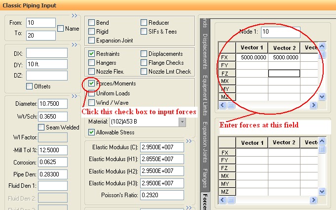
Applying PSV Reaction Force
The reaction force application philosophy for open discharge PSV (PSV output discharges into the atmosphere) connected systems is the same throughout the process industries. But for closed discharge, PSV connected system the force application philosophy varies from organization to organization. Some organization applies the reaction force for closed discharge PSVs but some organizations do not consider it. So users need to follow the company-specific project guidelines in such cases.
Where to Apply the PSV Reaction Force?
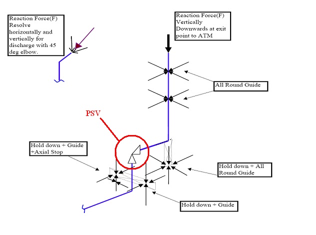
The following figure (Fig. 2) shows the points where the reaction force is required to be applied for open discharge PSVs.
Fig.2: Reaction force Application point for open discharge PSV connected systems
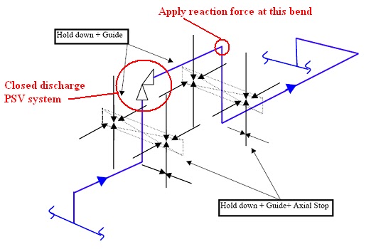
Fig. 3 shows the application point (If required) of reaction forces for closed discharge PSV connected systems.
Fig.3: Reaction force Application point for Closed discharge PSV connected systems
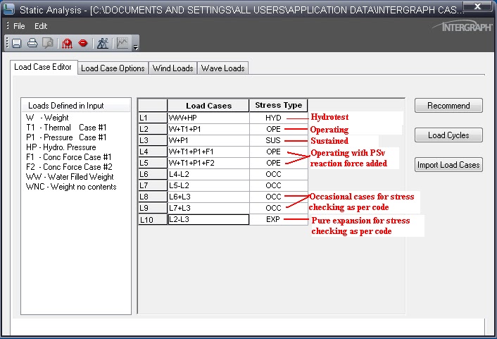
Caesar II Load Cases for PSV Connected Systems:
PSV forces are considered occasional forces. So occasional Stress due to PSV reaction force has to be calculated and to be limited within 1.33 times Sh (As per code ASME B31.3). Here Sh=Basic allowable stress at hot conditions. Based on company practice PSV reaction force is added either with a design temperature case or with an operating temperature case. Also, some organizations have the practice of making One PSV pop up and others stand by load cases. Accordingly, make the load cases as shown below:
Fig.4: Caesar II methodology to enter the reaction force
Fig.5: Caesar II simple load cases for analysis PSV connected system
The following load cases assume two temperatures (T1= operating temperature, T2= design temperature) along with Wind and Seismic load cases:
Load Case
Stress Type
Description
L1
WW+HP
HYD
Hydrostatic Case
L2
W+T1+P1
OPE
Operating temperature case
L3
W+T2+P1
OPE
Design temperature case
L4
W+T1+P1+F1
OPE
Operating temp+PSV reaction ( PSV 1 popping up)
L5
W+T1+P1+F2
OPE
Operating temp+PSV reaction ( PSV 2 popping up)
L6
W+T1+P1+WIN1
OPE
Operating temp+Wind from North
L7
W+T1+P1+WIN2
OPE
Operating temp+Wind from South
L8
W+T1+P1+WIN3
OPE
Operating temp+Wind from East
L9
W+T1+P1+WIN4
OPE
Operating temp+Wind from West
L10
W+T1+P1+U1
OPE
Operating temp+Seismic from North
L11
W+T1+P1-U1
OPE
Operating temp+Seismic from South
L12
W+T1+P1+U2
OPE
Operating temp+Seismic from East
L13
W+T1+P1-U2
OPE
Operating temp+Seismic from West
L14
W+P1
SUS
Sustained case
L15
L4-L2
OCC
Pure PSV Reaction
L16
L5-L2
OCC
Pure PSV Reaction
L17
L6-L2
OCC
Pure Wind
L18
L7-L2
OCC
Pure Wind
L19
L8-L2
OCC
Pure Wind
L20
L9-L2
OCC
Pure Wind
L21
L10-L2
OCC
Pure Seismic
L22
L11-L2
OCC
Pure Seismic
L23
L12-L2
OCC
Pure Seismic
L24
L13-L2
OCC
Pure Seismic
L25
L15+L14
OCC
Pure Occasional+Sustained
L26
L16+L14
OCC
Pure Occasional+Sustained
L27
L17+L14
OCC
Pure Occasional+Sustained
L28
L18+L14
OCC
Pure Occasional+Sustained
L29
L19+L14
OCC
Pure Occasional+Sustained
L30
L20+L14
OCC
Pure Occasional+Sustained
L31
L21+L14
OCC
Pure Occasional+Sustained
L32
L22+L14
OCC
Pure Occasional+Sustained
L33
L23+L14
OCC
Pure Occasional+Sustained
L34
L24+L14
OCC
Pure Occasional+Sustained
L35
L3-L14
EXP
Pure Expansion
L36
L2-L14
EXP
Pure Expansion
Table 1: PSV Piping System Stress Analysis Load Cases
Output Study:
Check Code stresses for load cases L1, L14, and L25 to L36. It is better to keep stresses for L1 and L14 below 60% and for the rest within 80%.
Check forces for load cases from L1 to L14.
Better Engineering Practices
It is a better practice to use 3-way restraints in both inlet and outlet piping of PSV-connected systems if feasible (As shown in figures 2 and 3 above). However if not possible then try to provide a 3-way restraint in the outlet only by layout modification.
In a normal operating case Safety valve inlet line temperature will be operating temperature up to the inlet of the safety valve and the Safety valve outlet line will be in ambient temperature up to the header.
Sometimes a Dynamic Load Factor (DLF) of 2 is used for calculating PSV reaction force.
If any stress failure or abnormal routing changes are required, then a certain local area from the header can be used at an average temperature of 2 meters or 5D which is higher (Safety valve outlet joining at header junction point) and also shall be taken process engineer’s approval.
If the connection of the PSV closed system is emerging from the header with 45˚ put SIF for this tapping. If required tapping point of the outlet line and outlet header shall be reinforced to reduce SIF.
In case any safety valve assembly is placed on the top platform of any vessel, Support can be taken either from the top platform or support can be arranged from the top portion of the vessel taking a clip from the vessel. In both cases, the load and locations of support or clip equipment vendors must be informed through the mechanical group along with the clip information.
Do not provide a spring below the safety valve inlet line
If you still have doubts, then you can enroll in the following video course that explains the stress analysis of the PSV piping system using Caesar II software.
Fire Protection systems are a very important part of safety in any operating plant as it provides a reasonable degree of protection to expensive equipment, property, documents, life, and inventory during a fire event. For Oil & Gas, Refinery, or plants those deals with Petroleum or similar flammable products, It must have to be in place to avoid major loss during uneven circumstances.
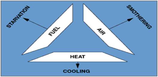
A Fire requires combustible materials, oxygen, and an energy source (heat) to provide ignition. Three components – fuel, oxygen & heat are referred to as the fire triangle.
Principle of Fire Extinction:
Starvation – Removing or blanketing the fuel
Smothering – Cutting off or diluting the oxygen supply
Cooling – Removing heat from the fire.
Fig. 1: Principles of Fire Extinction
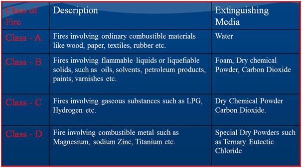
Types of Fire & Extinguishing Medium:
Fig. 2: Types of fire and extinguishing medium
Fire Fighting Agents:
Fire Fighting Agents are those substances that are used to reduce the effect of fire during fire events.Examples are:
Sand
Blanketing
Water
Steam
Carbon dioxide
Dry Chemical Powder
Aqueous Film Forming Foam (AFFF)
Properties of Petroleum Products:
For all flammable liquids, it is the vapor that burns and not the liquid.
Petroleum vapor is heavier than air so it has a tendency to descend on the ground or lower level or sump.
Petroleum is immiscible with water. Its specific gravity is less than 1, so they float on water
The electric conductivity of almost all petroleum products (except crude oil, ethanol, etc.) is very low and hence it generates static electricity during storage and transportation
Petroleum Products are divided into the following classes
Class A – Flashpoint < 23 deg.C
Class B – Flashpoint > 23 deg.C & < 65 deg.C
Class C – Flash point > 65 deg.C & < 93 deg.C
Unclassified – Flash point> 93 deg.C & above
Fire Protection Facilities in Petroleum Installations:
Fig. 3: Fire Protection Facilities
Codes and Standards for Fire Protection System Design
The following reference codes and Standards govern the design of Fire Protection System Design.
NFPA 24 – Standard for the Installation of Private Fire Service Mains and Their Appurtenances
NFPA 13 – Standard for the Installation of Sprinkler Systems
NFPA 15 – Water Spray Fixed System
NFPA 11 – Standard for Low, Medium, and High expansion foam
NFPA 16 – Standard for the Installation of Foam water sprinkler and Foam water Spray system
NFPA 20 – Standard for the Installation of Stationary Pumps for Fire Protection
NFPA 22 – Standard for Water Tanks for Private Fire Protection
NFPA 30 – Flammable and Combustible Liquids Code
IP 19 – Fire Precautions at Petroleum Refineries and Bulk Storage installations
DEP 80.47.10.31-Gen – Active fire protection systems and equipment for onshore facilities
Fire Protection System Design
The firefighting system should be designed based on the Single Fire Scenario.
The Facility should be divided into zones
The type of Fire Fighting system should be decided.
Fire-Water application rate and discharge time should be referred from IP-19 or NFPA standards.
Firewater demand for the facility should be calculated.
Similarly, the water required for the Foam system should be calculated.
The facility with the highest water demand is considered critical and based on this the Firewater storage tank and pump capacity should be determined.
What are the different types of fire protection systems?
Fire-Water Tanks: Above-ground storage tanks of adequate nos. to meet the norm of 2 hr. continuous firefighting (As per IP-19).
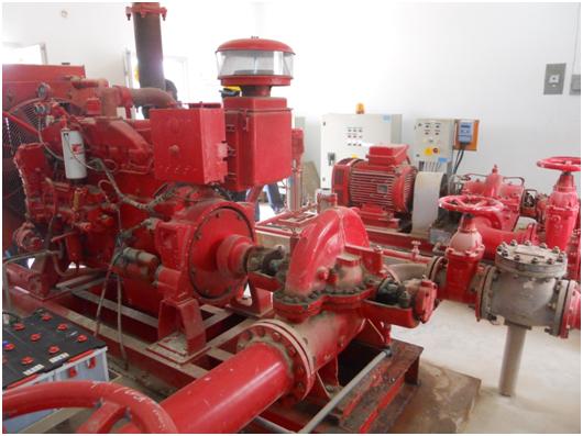
Fire-Water Pumps (Fig. 4) should be selected based on the largest firewater demand for the facility. Fire-Water Pumps should be selected as per NFPA requirements
Firewater pumps should be three basic types as a minimum:
Electrical Driven Pumps – Primary Considered as cost-effective but not mandatory
Diesel Driven pumps – Secondary considered but mandatory
Jockey pumps – Required to keep the hydrant system pressurized and to check the health of the Fire Water system
Fig. 4: A figure showing a Fire Water Pump
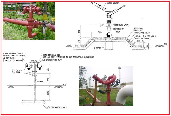
Hydrant Network in Fire Protection System
Hydrant Networks (Fig. 5) consist of Hydrants and Monitors.
Hydrants and Monitors should be placed at least 15 meters away from the hazard but not more than 45 meters.
Proper coverage should be checked for the hydrant and monitors ensure the facility under protection is adequately covered.
The hydrant mains can be laid above ground or underground.
The hydrant mains should form a closed loop ensuring multi-directional flow in the system. The layout should be such that the facility has access to Fire protection at any given time.
Isolation valves should be located at branches and other strategic locations.
Fig. 5: Figure showing a typical hydrant network
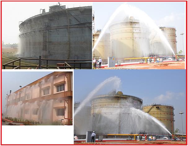
Water Spray System as Fire Protection System
The water spray system (Fig. 6) is provided for cooling the tank shell, and piping exposed to fire. The system is provided for cooling the structure on fire and exposure protection of adjacent property
The system consists of fixed piping with pipe fittings, isolation valves, NRV, and water spray nozzles.
In the case of tank and piping, the water spray directly impinges onto the surface of the tank or piping for cooling.
A spray ring should be installed between each tank wind girder.
NFPA 13 and NFPA 15 requirements should be met
Two types: Manual Water Spray system and Automatic Water Spray system
Fig. 6: Typical Water Spray System
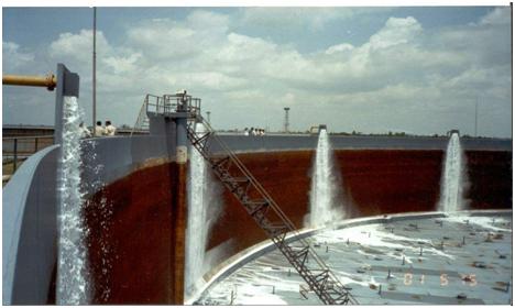
Use of Foam Pourer System (Fig. 7) in Fire Protection:
Semi-fixed foam Pourer system – Comprises fixed pipings and pipe fittings, drain valves, foam coupling, foam makers, foam pourer, and deflector plate on tank.
Mobile Foam tender is required for actuating the system.
Fixed foam pourer system( Manual/Automatic) – Manual system comprises of fixed foam concentrate storage shed, foam supply pumps, proportioning system, pipings, and pipe fittings, isolation valves, drain valves, foam coupling, foam makers, foam pourer and deflector plate on tank.
The automatic system requires motor-operated valves at different points and PLC for its actuation based on feedback from the automatic fire detection and alarm system.
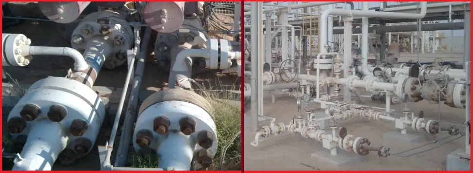
Flange leakage is a serious problem in the piping industry. It has a tremendous potential to cause severe hazards to operating plants. Hence, the possibility of leakage needs to be investigated during the design stage to reduce leakage possibility during operation.
Basically, flange leakage is a function of the relative stiffnesses of the flange, gasket, and bolting.
Flanges are designed to remain leak-free under hydrostatic test pressure when cold and under operating pressure when hot.
The design of flanges (ASME B16.5) does not take into account the bending moment in the pipe. This generates a wire drawing effect on the mating surface of the flange. Hence, additional flexibility is to be provided when a flange joint is located near a point of high bending moment. So, Leakage checking is required.
Flanges Used in Oil & Gas Processing Plants
Process Piping Flanges are designed in accordance with the ASME Boiler and Pressure Vessel Code, Section VIII, Division 1, Appendix 2, using allowable stress and temperature limits of ASME B31.3.
2. Reasons for Flange Leakage
Numerous possible reasons may cause a flange assembly to leak. Some of the common causes of flange leakage problems are:
Excessive Piping System Loads:
Forces and bending moments: can loosen bolts or distort flanges.
Causes include insufficient flexibility, excessive mechanical force, and poor support placement.
Incorrect Gasket Size or Material:
Wrong size: noticeable during installation.
Wrong material: This may cause issues like corrosion or blowouts later.
Vibration Levels:
Excessive vibration can loosen bolts, resulting in leaks.
Thermal Shock:
Rapid temperature changes can deform flanges and cause leaks, exacerbated by varying thermal expansions.
Improper Gasket Installation:
Off-center gasket: This leads to uneven compression and potential leaks.
Fastener Issues:
Too tight or not tight enough: uneven bolt stress due to improper tightening or loss of bolt tension over time.
Overly tight fasteners: excessive pressure on gaskets or fatigue on equipment, especially in high-temperature conditions.
Improper Flange Alignment:
Misalignment causes uneven gasket compression and potential leaks.
Flange Facing and Surface Finish:
Deeper serrations: Can prevent proper gasket seating, leading to leakage.
Damaged Flange Faces:
Corrosion pitting: Creates leakage paths.
Contaminants: Dirt, scale, scratches, protrusions, and weld spatter can lead to uneven gasket compression and leakage.
Most of the reasons mentioned above are construction-related, which can be eliminated by following proper best practices during construction activity. However, the major design cause that could result in flange leakage is excessive forces and moments that can be controlled during the design phase. The following section provides flange analysis methodologies to check the suitability of flanges against high forces, which may cause excessive stresses.
3. Flange Leakage Analysis Criteria
The criteria regarding when flange leakage checking is required should be mentioned in the ITB (Invitation To Bid) documents or project specs. But as a general practice, the following can be used:
Flanges with a rating of 600 or more
Flanges with a rating of 300 and size greater than 16 inch
4.1 Flange Leakage Checking by Pressure Equivalent Method
In this method, the generated axial force (F) and bending moment (M) on the piping/pipeline flange are converted into equivalent pressure (Pe) using the following equations.
Equivalent Pressure for Axial force, Pe1=4F/ΠG2
Equivalent Pressure for bending moment, Pe2=16M/ΠG3
Here G=diameter at the location of gasket load reaction =(Gasket OD+ID)/2 when bo<=6 mm =(Gasket OD-2b) when bo>6 mm. Here bo=basic gasket seating width as given in table 2-5.2 of ASME sec VIII
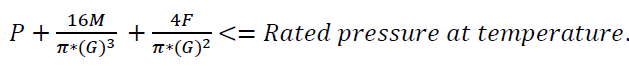
These two equivalent pressures are then added with pipe or pipeline system design pressure (Pd) to find the total pressure (Pt=Pd+Pe1+Pe2) and checked against the rated pressure at the temperature for the flange. The rated pressure is found in the ASME B16.5 (ASME B16.47 for flanges with size 26 inches and more) pressure-temperature rating table associated with flange material. If Pt is less than the allowed pressure on the rating table corresponding to the associated temperature, then the flange will not leak.
Hence the requirement for this method is Design Pressure (P):
4.1.1 Drawbacks of the Pressure Equivalent Method
The major drawbacks of the pressure equivalent method are:
The flange leakage analysis by the pressure equivalent method is too conservative, resulting in significant changes to the piping layout and support and hence impacting cost and schedule. In some cases, the allowable bending moment may be as low as 5% of the pipe yield.
It does not address the issue of bolting and gaskets, two important factors for controlling leakage.
The pressure equivalent method of flange leakage checking does not compute stresses in gaskets, bolts, or flanges. On the flip side, its overly conservative approach keeps the stresses on these components, subject to the proper selection of material, installation, and fabrication, to low magnitudes.
4.2 Flange Leakage Checking by ASME BPVC Sec VIII Div 1 Appendix 2 Method
This method is the widest one used in the industry where rules of ASME SEC III NC3658.3 are not applicable (B16.47 Flanges). In this method, flange stresses (longitudinal hub stress, radial flange stress, and tangential flange stress) are calculated based on ASME code-provided equations and formulas. These calculated stresses are then compared with allowable stresses as given in ASME BPVC Code Sec VIII Div 1 Appendix 2, Clause 2-8.
The mathematical basis for the computation of the stresses is in the work of Rossheim and Waters, where the governing equations for a circular plate (for the flange) and for a cylindrical shell (hub/pipe) under the action of internal pressure were supplemented with deformation compatibility at the interface between the hub and the ring and hub and pipe.
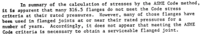
It’s important to note that many B16.5 flanges fail to meet the ASME code requirements, especially when a recommended magnitude of installation bolt stress of 40 Ksi is used. As Rodabaugh explains in Background of ANSI B16.5 Pressure Temperature Ratings (API 54-72).
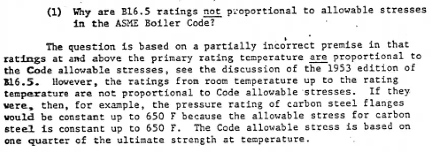
Also, in the same report, Rodabaugh answers certain critical questions –
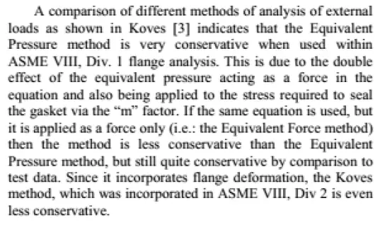
If ASME SEC VIII Div 1 Appendix 2 is implemented, then there is no way other than to convert the applied external bending moment and axial force as an “equivalent pressure,” which is what CAESAR II does. This approach can be seen as overly conservative, and the following is taken from ASME PVP-97814.
If however this method has to be implemented ( as many clients demand in their engineering standards), a few relaxations can be done, like checking if the computed bolt stress in seating and operating conditions are within 65% of SMYS for SS and 85% of SMYS for CS; alternately, if using the approach stated in ASM PCC-1 Appendix O, it can be shown that the combination of internal pressure and external bending moment and axial force is within the limits of equation (8), the joint can be qualified as acceptable.
For calculating flange stresses, one needs to calculate the flange moment, which is dependent on bolt load. Bolt load has to be calculated for two design conditions: operating & gasket seating and the most severe will govern. For more details on the equations and calculation methodology, the above-mentioned code can be referred to.
In this method, the flanges are evaluated using the ASME BPVC Section III Subsection NC-3658.3 method. The calculated flange moments are compared to some limited values as calculated from the code equations.
The theoretical basis for this method lies in the computation of bolt stress due to pressure and applied bending moment and ensuring that the flange is not overstressed. This brings out the inherent weakness of not addressing the issue of gaskets. This method also presupposes an application of 40 Ksi of tightening stress for B16.5 flanges.
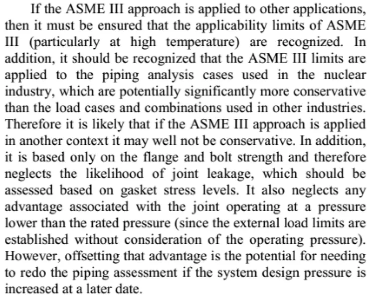
This method is recommended for high-strength bolts (allowable stress >20 Ksi) and for B16.5 Flanges. However, as the basis of computation is a control on bolt stress under pressure and bending moment and ensuring that flanges are not overstressed, its use in B16.47 Flanges can logically be extended, ensuring that the bolts and flanges are not overstressed. Moreover, as long as the applied bolt stress meets the requirements of ASME PCC-1 Appendix O, it ensures that the issue of adequate gasket compression is also taken care of, of course, subject to the condition that the flange is within the size limitation of ASME PCC-1 (48 inches). Some words of caution on the use of NC3658.3 from ASME PVP2013-97814 are shown below
For more details on the Caesar II application of the NC method, click here.
4.4 Flange Leakage Analysis Using EN-1591
The EN 1591-1 calculation code offers a comprehensive method for analyzing flange leakage by considering the behavior of all components involved—flanges, bolts, and gaskets. Unlike simpler methods, EN 1591-1 accounts for factors such as gasket thickness reduction due to flange stress and changes in gasket elasticity with temperature variations. This advanced approach provides not only an allowable stress check on the components but also an indication of the expected leak tightness of the flange assembly. It is applicable to both regular piping flanges and custom-designed body flanges for equipment. The code incorporates gasket characteristics based on EN 13555, including maximum allowable surface pressures, modulus of elasticity, and minimum seating pressure for various tightness classes. Additionally, it factors in the coefficient of thermal expansion of flange and bolt materials
4.5 Some Other Flange Leakage Methods
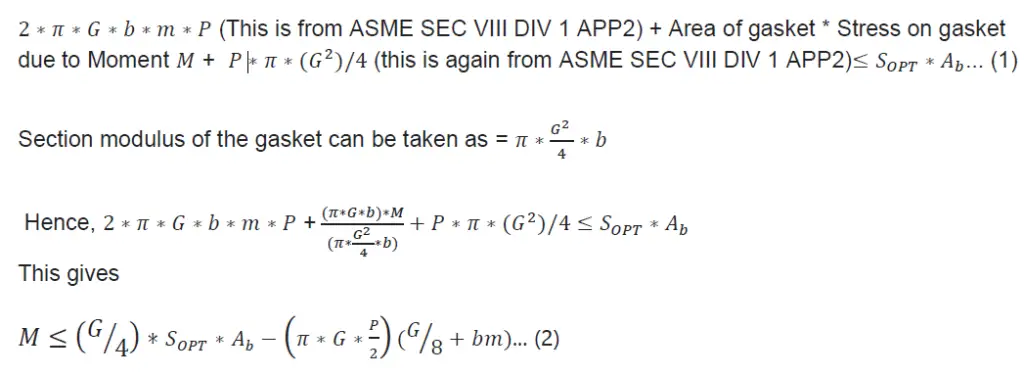
4.5.1 Blick’s method
In essence, this method stands for -Internal Pressure force on gasket + residual compressive force on gasket + force on gasket due to applied bending moment should be equal to operating stress on each bolt times total bolt area.
4.5.1.1 Derivation of Blick’s formula-
4.5.1.2 Drawbacks of this method-
Relative deformation and stiffness of bolts, gaskets, and flanges are not considered.
Flange stress is not discussed.
How to calculate operating stress on bolts is not discussed.
The basis for the m factor in ASME B&PV code Sec VIII Div 1 Appendix 2 is not known, and hence their accuracy is a question by itself.
An improvement of this method can be to compute 𝑆𝑂𝑃𝑇 using ORNL2913.3 [8] and ASME PCC-1 Appendix O
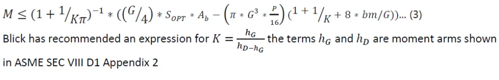
4.5.1.3 Modified Blick’s Formula
Blick proposed modification to the above formula (eon) and the modified version of Blick’s method is
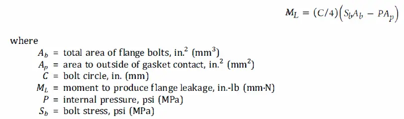
4.5.2 ASME B31.8 Method of Flange Leakage Analysis
The essence of this method is that when the force on the BJF due to applied internal pressure and applied bending moment (converted to a force) reaches a critical value, residual stress on the gasket equals zero.
As per ASME B31.8, Table E1, Note 14, the moment to produce leakage of a flanged joint with a gasket having no self-sealing characteristics can be estimated by the following equation:
4.5.2.1 Drawbacks of the method-
The effect of applied loading on Flange and hub stress is not discussed
Gasket stress is not discussed.
Bolt preload and the load reduction in the bolt are not discussed.
Relative deformation and stiffness of bolts, flanges, and gaskets are not discussed.
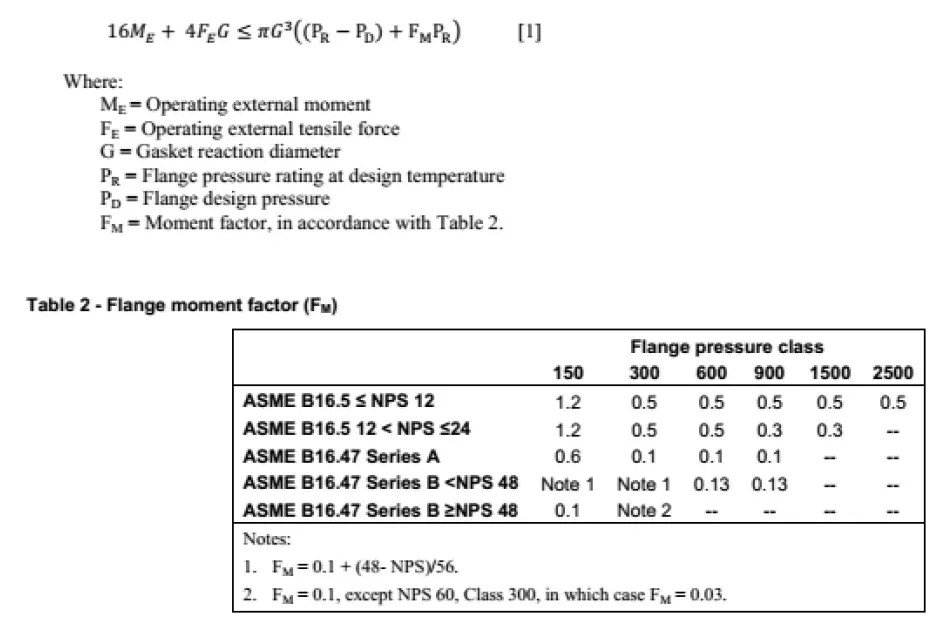
4.5.3 New method developed by Integrity Solutions (Warren Brown), Australia
The following is taken from the paper ASMEPVP2013-97814, citing the relevant equation for the new method:
5. Recommended Good Practices to Avoid Flange Leakage
Here are some of the recommended practices that can be followed to avoid flange leakage issues:
The acceptable limit of bolt stress during tightening- 65% of SMYS for SS and 85% of SMYS for CS.
Use of proper lubricant- Molybdenum disulphide.
Bolt load scatter should be considered with a typical value of 5-10% of the target value.
Although tensioning, in general, is a better approach than torquing, but for l/d ratio or length-to-diameter ratio of bolts to <=3, tensioning is normally not recommended.
Two factors govern the loss when using bolt tensioning: Tool load loss factor (TLLF) and Flange load loss factor (FLLF); the latter being the additional case when 100% tensioning is not possible/applied. This aspect has to be considered when applying the right magnitude of bolt stress. The challenge will be to ensure that even with consideration of TLLF and FLLF, the bolt stress should not go beyond 65% of SMYS for SS and 85% of SMYS for CS.
Ambiguity appears between sections 5.3.4 and 5.4.2 of B16.5 on the selection of a proper gasket for low-strength bolts. Since the use of low-strength bolting does not allow high gasket stress levels to be achieved during assembly, this issue should be considered in selecting a proper gasket for use with low-strength bolts. The same recommendation should be followed in B16.47 (for this document, the ambiguity on the same issue is exhibited in the paragraphs with the same no’s as in B16.5). For B16.5 the referenced edition is 2013 and for B16.47 the referenced edition is 2010.
To avoid problems with sealing, it is recommended that the purchased flanges be having a 3.2*10-3 m concentric groove surface finish with a nominal 5 mm tool nose radius and 0.45 mm pitch. This is in relation to avoiding problems with leakage with spiral finish and 250*10-3 mm surface finish (section 6.4.5.3 of B16.5). The same recommendation should be followed in B16.47 (relevant paragraph 6.1.4.2 in B16.47) For B16.5 the referenced edition is 2013 and for B16.47 the referenced edition is 2010.
For accepting flanges with imperfections, it is recommended that the limits outlined in ASME PCC-1-2013 Appendix D be used in lieu of Section 6.4.6 of B16.5; the same recommendation should be followed in B16.47 (the relevant paragraph is 6.1.5). For B16.5 the referenced edition is 2013 and for B16.47 the referenced edition is 2010.
It is recommended that the minimum hub height be limited to greater than 75% of the full hub height. The same recommendation should be followed for B16.47.
When using B16.20 gaskets with B16.47 Series A Class 150 flanges, custom dimensions should be specified ( the ideal gasket sealing element OD is between 6 mm and 12 mm smaller than the flange seating surface OD) such that the OD of the sealing surface is closer to the raised face O. The dimensions as they are in B16.20 can result in joint leakages.
For selecting minimum pipe wall thickness for the use of spiral wound gaskets with inner rings and B16.5 flanges, the minimum specified dimensions in B16.20 (Table 15 in the 2012 edition of B16.20) should be followed. Recommendations in Tables 16 and 17 of the 2012 edition (maximum bore of B16.5 Flanges for use with spiral wound gaskets and maximum bore of B16.47 Series A flanges for use with spiral wound gaskets) should also be followed.