Piping Stress Analysis is simply creating the load cases required for analysis and studying the impact of the same on the behavior of the critical piping systems. A load case can be defined as a set of loads (Weight, Pressure, Temperature, External Forces, Displacements, etc) and boundary conditions for defining a particular loading condition. So Stress Analysis can not be thought of without proper load case creation. Sometimes these load cases are mentioned in the piping stress analysis design basis. In this article, we will learn the basic load cases that are required for stress analysis activity.
Objectives of Pipe Stress Analysis:
The main objectives of stress analysis are to ensure:
- Structural Integrity (Design adequacy for the pressure of the carrying fluid, Failure against various loading in the life cycle, and Limiting stresses below code allowable.)
- Operational Integrity (Limiting nozzle loads of the connected equipment within allowable values, Avoiding leakage at joints, Limiting sagging & displacement within allowable values.)
- Optimal Design (Avoiding excessive flexibility and also high loads on supporting structures. Aim towards an optimal design for both piping and structure.)
What is a Load Case in Pipe Stress Analysis?
In the context of pipe stress analysis, a load case refers to a specific scenario or combination of loads that the piping system may experience during its lifecycle. These loads can arise from various sources such as internal pressure, temperature changes, external forces, and more. By analyzing these load cases, pipe stress engineers can predict how the piping system will behave under different conditions, allowing them to design systems that can withstand these stresses without failure.
A typical example of a load case in Caesar II pipe stress analysis may constitute the thermal, deadweight, and pressure loads together known as the operating load case. Similarly, a sustained load case is composed of dead weight and pressure load. Again, a load case can also be formed by combining the results of other load cases. For instance, a load case might represent the difference in displacements between the operating condition and the installed condition.
Notations Used for Load Cases in Caesar II
To meet these objectives several load cases are required during stress analysis. In this article we will use the following notations for building load cases:
- WW=water filled weight of the piping/pipeline system,
- HP=Hydrotest Pressure,
- W=Weight of pipe including content and insulation,
- P1=Internal Design pressure,
- T1=Maximum Design temperature,
- T2=Maximum Operating temperature,
- T3= Minimum Design temperature,
- WIN1, WIN2, WIN3, WIN4: wind loads acting in some specific direction,
- U1, U2, U3, U4: uniform (seismic) loads acting in some specific direction.
Basic Load Cases for Caesar II Pipe Stress Analysis:
For Stress analysis in Caesar II, Various Load case combinations are used which serve several purposes. While analysis at a minimum, the stress check is required for the below-mentioned cases:
a. Hydrotesting case:
Piping/ Pipeline systems are normally hydro-tested (sometimes pneumatic tested) before the actual operation to ensure the absence of leakage. Water is used as the testing medium. So during this situation pipe will be subjected to water-filled weight and hydro-test pressure.
Accordingly, our first load case will be as mentioned below
| 1 | WW+HP | HYD |
b. Operating and ALT Sustained load cases:
When the operation starts working fluid will flow through the piping at a temperature and pressure. Alt Sustained cases are used as Hot Sustained cases which means sustained stress that the system carries during operation. So accordingly our operating load cases will be as mentioned below:
| 2 | W+T1+P1 | OPE | For operating temperature case at maximum design temperature |
| 3 | W+P1 | SUS | Alt Sustained case based on operating case 1 (T1) |
| 4 | W+T2+P1 | OPE | For a maximum system operating temperature case |
| 5 | W+P1 | SUS | Alt Sustained case based on operating case 1 (T2) |
| 6 | W+T3+P1 | OPE | For minimum system temperature case |
| 7 | W+P1 | SUS | Alt Sustained case based on operating case 1 (T3) |
c. Sustained Load Case:
Sustained loads will exist throughout the plant operation. Weight and pressure are known as sustained loads. So our sustained load case will be as follows:
| 8. | W+P1 | SUS |
d. Occasional Load Cases:
Piping may be subjected to occasional wind and seismic forces. So to check stresses in those situations we have to build the following load cases:
| 9 | W+T2+P1+WIN1 | OPE | Considering wind from +X direction |
| 10 | W+T2+P1+WIN2 | OPE | Considering wind from -X direction |
| 11 | W+T2+P1+WIN3 | OPE | Considering wind from +Z direction |
| 12 | W+T2+P1+WIN4 | OPE | Considering wind from -Z direction |
| 13 | W+T2+P1+U1 | OPE | Considering seismic from +X direction |
| 14 | W+T2+P1-U1 | OPE | Considering seismic from -X direction |
| 15 | W+T2+P1+U2 | OPE | Considering seismic from +Z direction |
| 16 | W+T2+P1-U2 | OPE | Considering seismic from -Z direction |
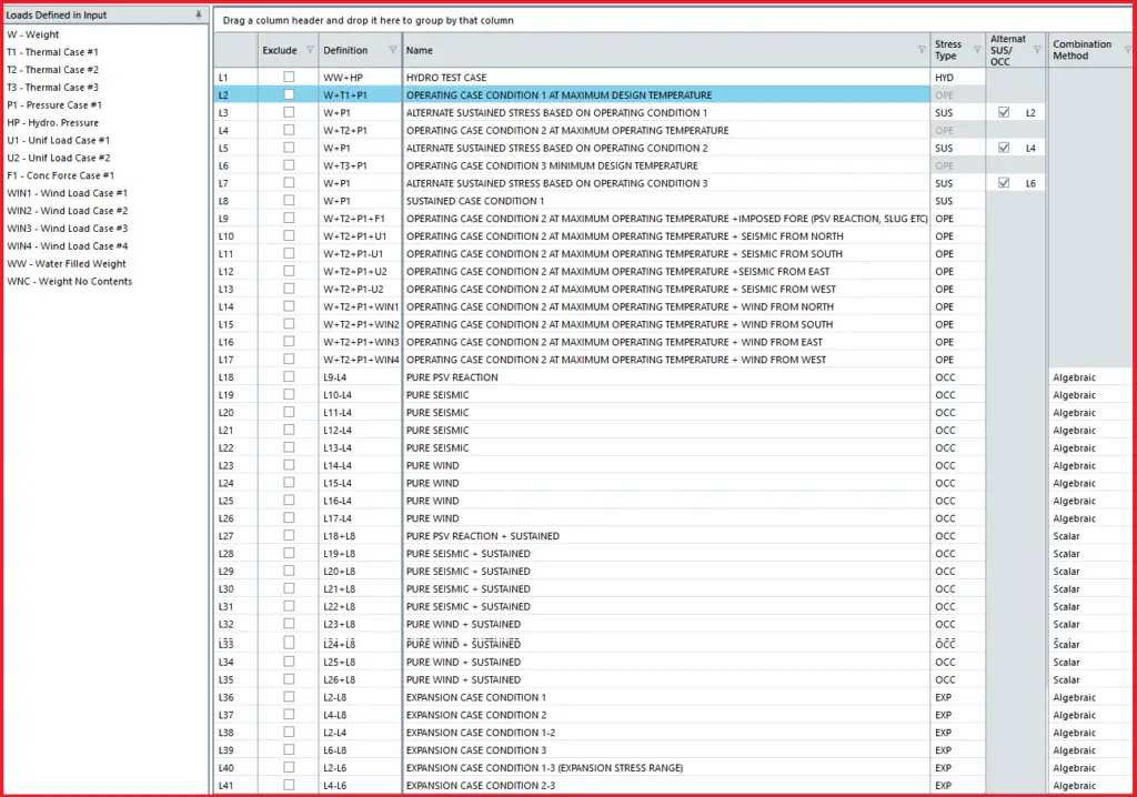
While stress analysis the above load cases from load case 9 to load case 16 are generated only to check loads at node points. Figure 1 shows typical load cases that should be generated during stress analysis
To find occasional stresses we need to add pure occasional cases with sustained load and then compare them with code allowable values. The following sets of load cases are built for that purpose.
| 17 | L9-L4 | OCC | Pure wind from +X direction |
| 18 | L10-L4 | OCC | Pure wind from -X direction |
| 19 | L11-L4 | OCC | Pure wind from +Z direction |
| 20 | L12-L4 | OCC | Pure wind from -Z direction |
| 21 | L13-L4 | OCC | Pure seismic from +X direction |
| 22 | L14-L4 | OCC | Pure seismic from -X direction |
| 23 | L15-L4 | OCC | Pure seismic from +Z direction |
| 24 | L16-L4 | OCC | Pure seismic from -Z direction |
| 25 | L17+L8 | OCC | Pure wind+Sustained |
| 26 | L18+L8 | OCC | Pure wind+Sustained |
| 27 | L19+L8 | OCC | Pure wind+Sustained |
| 28 | L20+L8 | OCC | Pure wind+Sustained |
| 29 | L21+L8 | OCC | Pure seismic+Sustained |
| 30 | L22+L8 | OCC | Pure seismic+Sustained |
| 31 | L23+L8 | OCC | Pure seismic+Sustained |
| 32 | L24+L8 | OCC | Pure seismic+Sustained |
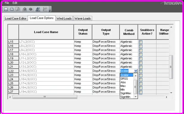
Load cases from 25 to 32 will be used for checking occasional stresses with respect to the code ASME B31.3 allowable (=1.33 times Sh value from code). Use scalar combination for load cases 25 to 32 above and algebraic combination for others as shown in Fig. 2 attached below:
e. Expansion Cases:
Following load cases are required for checking the expansion stress range as per the code
| 33 | L2-L8 | EXP |
| 34 | L4-L8 | EXP |
| 35 | L6-L8 | EXP |
| 36 | L2-L6 | EXP |
The above load cases (from 33 to 36) are used to check the expansion stress range
The above-mentioned load cases are the minimum required load cases to analyze any stress system. Out of the above load cases, the load cases mentioned in load case numbers 1, 3, 5, 7, 8, and 25-36 are used for stress checks. The load cases mentioned in load case numbers 1, 2, 4, and 6 to 16 are used for checking restraint forces, displacements, and nozzle load checking.
Some additional load cases may be required for PSV-connected systems, systems having surge or slug forces, and rotary equipment-connected systems.
Seismic and Wind analysis may not be required every time. So those load cases can be deleted if the piping system does not fall under the purview of wind and seismic analysis by project specification. However, to perform wind and seismic analysis proper related data must have to be entered in the Caesar II spreadsheet.
If the stress system involves the use of imposed displacements (D) and forces (F) then those have to be added with the above load cases in the form of D1, D2, or F1, F2 as applicable.
Better Engineering Practices for Stress Analysis
It is a better practice to keep:
- Hydro and sustained stresses below 60% of the code allowable
- Expansion and occasional stresses below 80% of the code allowable
- Sustained and Hydrotest sagging below 10 mm for process lines and below 3 mm for steam, two-phase, flare lines, and free-draining lines.
- Design/Maximum displacement below 75 mm for unit piping and below 200 mm in rack piping.
Video Tutorial for Load Case Creation in Caesar II
The following video tutorial explains the load case creation steps with an example
Online Course on Pipe Stress Analysis with Practical Example
Complete Pipe Stress Analysis using Caesar II Online Course (30+ Hours)