The full form of HVAC is Heating, Ventilation, and Air Conditioning. Appropriate HVAC provides comfort for people & maintains an effective Environment for surroundings. Proper HVAC Allows humans to exist under adverse conditions. The requirement of HVAC Systems is a must for critical areas like Control rooms, Electronic Equipment Rooms, switchgear halls, Battery rooms, workshop areas, etc. in a petrochemical plant. HVAC systems are designed following basic principles of thermodynamics, heat transfer, and fluid mechanics. The main purpose of the HVAC system is to adjust and change the outdoor air conditions to the desired conditions of occupied buildings for achieving the thermal comfort of occupants. Outside air is drawn inside the buildings and either heated or cooled depending on the outdoor condition. The air is then distributed into the occupied spaces.
Objectives of HVAC Systems
The Primary Intent of HVAC systems is the Comfort of occupants. Other major objectives are
- Maintaining environmental conditions (temperature and humidity) appropriate to the operating requirements.
- Increase in Productivity.
- Building & Equipment Durability.
- Maintaining pressurization between hazardous and non-hazardous areas.
- Increase Life & Health.
- Dilution and removal of potentially hazardous concentrations of flammable/toxic gaseous mixtures in hazardous areas.
- Filtration of dust, chemical contaminants, and odors through chemical and carbon-activated filters.
- Inside condition of 21–24°C & 50–60% Relative Humidity is most comfortable & purity of air.
- The isolation of individual areas and control of ventilation in emergency conditions, through interface with the shutdown logic of the fire and gas detection and alarm safety systems.
However, note that an HVAC system is not intended to prevent catastrophic events such as the release of toxic and/or hazardous gases. Also, HVAC can not compensate on its own, for the intrinsic safety design features such as structural stability, coatings, area segregation, fire protection systems, etc. It only aids the safety process.
HVAC system components
The HVAC system components that condition the air to maintain the thermal comfort of space and occupants and achieve the required indoor air quality are:
- Air filter
- Supply fan
- Mixed-air plenum and outdoor air control
- Exhaust or relief fans and an air outlet
- Outdoor air intake
- Ducts
- Terminal devices
- Heating and cooling coils
- Self-contained heating or cooling unit
- Return air system
- Cooling tower
- Boiler
- Control
- Humidification and dehumidification equipment
- Water chiller
Types of HVAC Systems
There are four major types of HVAC systems available in different sizes. They are:
- Split HVAC systems
- Hybrid Heat Split HVAC systems,
- Duct-free or Ductless HVAC systems, and
- Packaged heating and air HVAC systems.
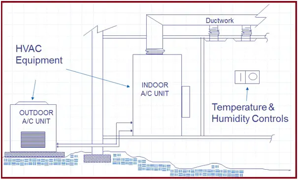
Split HVAC Systems:
A split HVAC system is the most common and classic type of HVAC system providing energy efficiency at lower costs. In this model, components are kept both outsides and inside the building and the system is split between two main units, one for heating, and one for cooling. The installation of split HVAC systems is quite complex; So must be performed under expert supervision. Typically, a split HVAC system consists of
- An outdoor component, or a condenser, such as an air conditioner or a heat pump.
- An indoor component that consists of an evaporator coil or fan, along with furnaces that convert refrigerant and help circulate air.
- A system of ducts that circulate air from the HVAC unit throughout the building.
- A programmable or non-programmable thermostat to manage the system.
- Accessories like purifiers, air cleaners, UV lamps, or humidifiers improve indoor air quality and comfort.
Hybrid Heat Split HVAC systems:
Hybrid Heat Split HVAC systems are basically an advanced form of split system with improved energy efficiency and lower utility bills. This type of HVAC system typically consists of
- An evaporator coil and furnaces that work to convert refrigerant and circulate air.
- A heat pump to cool or heat refrigerant.
- An oil or gas furnace.
- Ducts to take the warm or cool air throughout the building.
- Accessories to improve indoor air quality.
Duct-free or Ductless HVAC systems:
A duct-free or mini-split HVAC system is a unique ultra-efficient HVAC system with large upfront costs. It provides big benefits for certain needs and applications where conventional systems of ducts cannot be used.
Duct-free or ductless HVAC systems consist of the following components:
- An air conditioner or heat pump to cool or heat refrigerant.
- Wires and tubes to connect refrigerant from the outdoor unit to the fan coil.
- A compact fan coil.
- A thermostat to manage the system.
- Indoor air quality accessories.
Packaged heating and air HVAC systems:
Packaged heating and air HVAC systems are best suited for buildings without enough indoor spaces for split system components. In such HVAC systems, all components come together in one single package. So, easier to install. But the packed system is outside and exposed to extreme weather conditions, so can be damaged easily. A packaged heating and air HVAC system generally consist of:
- A heat pump, gas furnace, air conditioner, and the fan coil and evaporator reside in one unit
- An interface/thermostat on the front of the unit controls the system.
- Optional indoor air quality accessories.
Depending on the primary equipment location, HVAC systems can be classified as
- Centralized HVAC Systems and
- Decentralized or Local HVAC Systems.
The major differences between Centralized and Decentralized HVAC Systems are provided in the following table:
| Centralized HVAC system | Decentralized or Local HVAC system |
| Visually appealing as mechanical equipment is hidden in the mechanical room. | Visually not appealing. |
| Less Flexible. | The flexibility of operating different building parts at selected times. Also, flexible to maintain the different temperatures at different building parts. |
| Less Energy Efficient | Efficiency is more. |
| Higher installation and operating cost | Lower operating and installation costs. |
| Easy maintenance and Lower maintenance cost | Difficult to maintain and the cost is higher. |
| Standby equipment is accommodated for troubleshooting and maintenance | No backup or standby equipment |
| Long service life | Reliable equipment, but the estimated service life is normally less. |
HVAC System Selection
The selection of HVAC systems for a given building depends on various factors as mentioned below:
- The climate.
- The shape, size, function, architectural design, and age of the building.
- The individual preferences of the owner/HVAC designer.
- Occupant density.
- The project budget (Initial cost, Operating cost, Maintenance cost, Life-cycle cost)
- Environmental Impact, Noise, etc.
- Performance Parameters like Heating capacity, Cooling Capacity, Humidity, Efficiency, Sustainability, Constructibility, Particulate Controls, Ventilation, etc
- Life Span.
- Controls.
- Energy Consumption.
- Time available for construction.
HVAC system requirements
An HVAC system is primarily based on the following four requirements:
- Primary equipment
- Space requirement,
- Air distribution, and
- Piping
Primary equipment includes heating equipment (steam boilers/hot water boilers), air delivery equipment (centrifugal fans, axial fans, and plug or plenum fans), and refrigeration equipment (water chillers or refrigerants).
To specify an HVAC system as per design requirements, Space is required for the following facilities:
- Equipment rooms
- HVAC facilities
- Fan rooms
- Vertical shaft.
- Equipment access space for installation, replacement, and maintenance.
Air distribution represents the ductwork for delivering the conditioned air to the desired area in a direct, quiet, and economical way. It consists of air terminal units, fan-powered terminal units, variable air volume terminal units, all-air induction terminal units, and air-water induction terminal units. To prevent heat loss and save energy, all the ductwork and piping should be insulated. To host ductwork, buildings should have enough ceiling space.
The piping system is essential to deliver refrigerant, cooled water, steam, hot water, gas, and condensate to and from HVAC equipment in a direct, quiet, and affordable way. Piping systems in HVAC design are normally divided into two parts: the piping in the central plant equipment room and the delivery piping. Depending on the governing code requirement, HVAC piping may or may not be insulated.
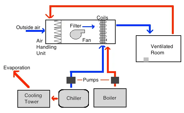
How does an HVAC System Work?
Fig. 1 below shows a schematic diagram explaining the basic function of an HVAC system:
Basic Refrigeration Cycle:
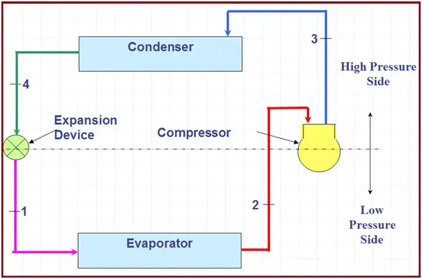
Air Conditioning Capacity – The “Ton”:
- One Ton of Refrigeration (TR) is defined as the quantity of heat removed to freeze 1 Ton (1 American short ton is 2000 pounds) of water into ice from and at 0°C in 24 hours.
- 1 Ton of Refrigeration = 12000 Btu/hr or 3024 Kcal/hr
TR = Q x Cp x (Ti – To) / 3024
- Q = mass flow rate of coolant in kg/hr
- Cp = coolant specific heat in KCal /kg deg C
- Ti = inlet, the temperature of the coolant to the evaporator (chiller) in °C
- To = outlet temperature of coolant from the evaporator (chiller) in °C
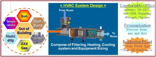
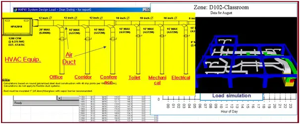
Major Work in HVAC (Fig. 3):
- The design of an HVAC system for plant buildings, requires specific temp., humidity, internal pressure, and cleanliness under various conditions.
- Preparation of Heat load Calculations, System Diagram, and Duct/Piping Plan.
- Equipment Sizing & Selection.
HVAC Work Flow:
Tools and Products:
E20-II, Elite
- System Capacity Report (Fan, Cooling, Heating, Humidification)
- Year Simulation (Power, Operation, Cost)
- Load Analysis by Each Room
Scope of work:
- Preliminary Design
- Vendor Print Checking
- Engineering
- Field Engineering
Basic HVAC Equipment:
- Fans / Blowers
- Air Handling Units (AHU)
- Filters
- Compressor
- Condensing units
- Evaporator (cooling coil)
- Control System
- Air Distribution System
Common HVAC System Types:
- Window / Split AC
- Duct-able Splits
- Packaged Units
- Fan Coil Units
- VRV Units
- Direct Expansion System
- Chilled Water System
Split System:
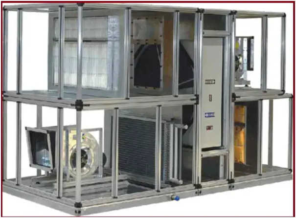
Air Handling Unit (AHU):
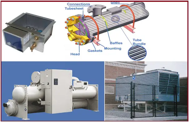
HVAC Equipment (Fig. 7):
- Chillers
- Heat Exchangers
- Cooling Towers
- Humidifiers
Air Distribution:
- Ductwork
- Metal
- Flexible
- Duct board
- Grilles, Louvers, & Registers
- Dampers
- Shut off
- Fire
- Smoke
- Sealants
- Supports
HVAC Codes and Standards
Various well-established codes and standards that are followed at different stages of HVAC system design are listed below:
- ISO 15138, Heating, ventilation, and air-conditioning.
- NORSOK Standard H-001, Heating Ventilation, and Air-conditioning.
- ASHRAE Standard 55 – Thermal Environmental Conditions for Human Occupancy.
- ANSI/API RP 500: Recommended Practice for Classification of Locations for Electrical Installations at Petroleum Facilities of Class 1 Division 1 or Division 2.
- ASHRAE Standard 62.1 – Ventilation for Acceptable Indoor Air Quality.
- BS 5925: Ventilation principles and designing for natural ventilation.
- ASHRAE Standard 90.1 – Energy Standard for Buildings Except for Low-Rise Residential Buildings.
- BS EN 60079-10: Electrical apparatus for explosive gas atmospheres, Part 10. Classification of hazardous areas.
- IP, Model Code of Safe Practice for the Petroleum Industry: Part 15
- IS – 12332 For Ventilation in Petrochemical Plants & Refineries.
- IS – 3103 For Industrial Ventilation.
- OISD – 163 Safety of Control room for the Hydrocarbon industry.
Online HVAC Courses
The below-mentioned online courses will help to upgrade your knowledge to the next level. So, click on the subject you are interested in learning, review it first, and then enroll if you feel suitable for you:
- HVAC Psychrometry, Air Handling System, and Duct Selection
- HVAC with HAP|Excel|AutoCAD|Manual Calculations
- HVAC Fundamentals and BMS Controls
- Become an HVAC Professional – Part 1/3- Fundamentals & Basics
- HVAC with Revit MEP & Practical Projects
- Become an HVAC PRO_The Ultimate HVAC Guide
- HVAC System Commissioning Procedures
- HVAC Heat and Cooling Load Calculation