Use of Dynamic Restraints
Whenever unplanned dynamic events occur, Dynamic restraints carry the responsibility of protecting the piping and other components from damage. Undesirable abrupt movement of the components in the system can be caused by:
- Pressure shocks from valve operation/ PSV
- Water hammer
- Boiler events
- Pipe breakage
- Wind load
- Mechanical vibrations are transmitted from pumps, compressors, turbines, or other process equipment.
- Seismic events
- Fluid disturbances
- Explosions etc.
Dynamic restraints are specially designed to absorb a sudden increase in load from the pipe and transfer into the structure and to dampen any opposing oscillation between the pipe and the structure. These restraints are not intended to carry the weight of pipework and should not impede the function of the supports. Dynamic restraints are required to be very stiff, to have high load capacity, and to minimize free movement between pipe and structure.
Types of Dynamic Restraints
The main supports that make up the dynamic restraints for process piping are-
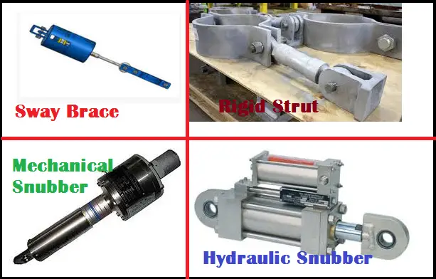
- Sway Braces
- Hydraulic and Mechanical Snubbers
- Rigid Struts
- Pipe Clamps
- Welding Clevis etc.
In the following paragraphs, we will discuss in brief about Sway Braces, Rigid Struts, and Snubbers.
What is a Sway Brace?
Sway braces can be defined as spring-loaded units mounted on pipework that is used to limit the swaying or vibration induced by external forces (vibration force) by applying an opposing force on the pipe. They are double-acting variable spring units that can handle both tensile and compressive loads. It is commonly used to allow unrestrained thermal movements while “tuning” the system dynamically to eliminate piping vibration. It could be pre-loaded in the cold or installed position so that after thermal pipe movement (growth) it reaches the neutral position and the load on the system in the operating (OPE) condition is negligible (almost zero).
Working of Sway Brace
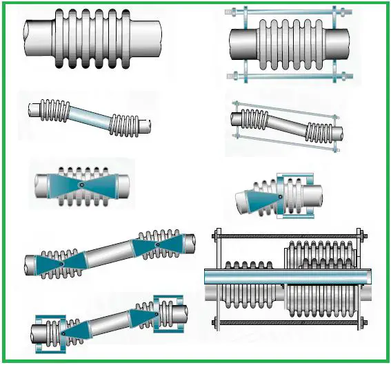
The construction is fairly simple, the unit has two piston plates: one on either side of the helical coil compression spring connected by a single-piston rod.
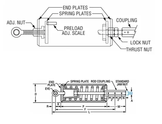
If a tensile load is applied, the top piston plate is pulled down causing the spring to compress & if a compressive load is applied the thrust nut/rod coupling pushes the bottom piston plate push up which causes the spring to compress. Therefore in both of the situations, the spring gets compressed but due to design (see the cutaway section above) the unit is capable of handling both compressive & tensile movements /forces.
The spring is pre-compressed (usually a full inch =25 mm) providing an initial force (preload) that instantaneously opposes vibration. Whenever any movement from the sway brace neutral position occurs it is opposed by a load equal to the pre-load plus travel from the neutral position times the sway brace spring constant. To explain it further, if the piping load on the sway brace is less than preload then there will not be any line movement. If the load is equal to preload then the line will be on the verge of movement, but then also the line will not move. If the load is more than the preload the line will deflect causing the spring to compress further. The deflection of the spring/pipe in this case will be as given in equation 1.
Pipe deflection= (piping load – Preload)/spring rate Equation 1
So there is no pipe movement if the load is less than the preload and with a load in excess of preload the deflection is as given in Eqn 1.
When a sway brace with a preload P is installed in a pipe there is no force exerted by the sway brace on the pipe. But for the pipe to have any movement in either direction along the line of sway brace installation it will experience a reactive force equal to P plus travel from neutral position times the sway brace spring constant. It is desired to have no force on the pipe during normal operation of the pipe. So sway braces are normally attached during normal operation or adjusted to the neutral position during the normal operating condition.
When the maximum allowed travel (usually 3-in. / 75 mm in either direction) is reached the sway brace locks prevent additional movement and act as a rigid restraint.
The preload for LISEGA sway braces can be adjusted as per requirement at the site. But for C&P or others, the unit is shipped after adjusting the required preload.
The effect of the sway brace on the piping system is to increase the K value in the equation
Mx2(t) +Cx(t) +Kx(t)=F(t)
This in turn will raise the natural frequencies of the vibratory modes & thus normally reduce the response of the pipe to dynamic loads & vibrations.
The force required to restrain the pipework can be calculated as follows:
If the pipework is vibrating with frequency f Hz at a maximum displacement (half amplitude) of x mm then, in simple harmonic motion, the restoring force exerted by the pipework at maximum displacement (kgf) = 4π2 f2 m x/1000 g. Where m is the equivalent mass of the pipework in kg.
It is likely that a Sway Brace having a preload greater than this value willfully restrains the pipe at the support location, while a Sway Brace for which this value is greater than the preload but less than the maximum load will have a significant effect.
Manufacturers normally recommend a specific size of sway brace for a pipe’s nominal diameter. If the exact restraining force required to control the piping vibration is known beforehand then a more specific sway brace selection is possible. The energy necessary to control the piping system is proportional to the mass, amplitude of movement, and the external force which is causing the vibration. From this relation, the exact restraining force required to control the piping vibration can be calculated and an appropriate sway brace size can be selected.
Sway braces need to be installed in operating condition. However, it can be installed in cold conditions. But in that case, when the plant starts operating, the pipe may have thermal movements. This may cause the spring in the sway brace to compress by an amount equal to the thermal movement/displacement. At this point, the sway brace will be exerting a force equal to the pre-load + movement X spring constant. The load needs to be released by doing a “Neutral adjustment”. This can be achieved by rotating the Rod coupling shown above in a direction such that the piston plate gets released & rests against the endplate. In this situation, the sway brace will not exert any force on the pipe. During the shutdown, as the pipe cools & gets into the cold position, the sway brace will exert a force on the pipe as the spring will get compressed. To summarize,
Sustained loads on sway brace = Pre-Load + Hot Deflection * Spring Rate
In OPE case the displacement allows thermal expansion and the sway assumes a neutral position exerting zero or negligible load on the pipe. i. e, Operating case restraint loads on sway brace =~ 0.0 (does not restrain thermal expansion)
Major Application of Sway Braces
Sway Braces are mainly used to reduce pipe vibration amplitude and at the same time do not increase the expansion stress in operating cases. It prevents the pipe from vibrating at its resonant frequency. Typical examples of using the sway braces are in the pipeline feeding the flare stack in a refinery. When gases at very high pressures are passed in the pipeline in the flare stack, it tends to vibrate & the sway brace will try & limit the vibrations. Every time the vibrating force has to act as opposed to the sway brace preload+ the stiffness multiplied by the distance moved from a neutral position. When the line movement exceeds the sway brace becomes rigid and acts as a rigid guide in that direction.
The spring stiffness and preload are fixed depending on pipe size. However, for special applications manufacturer can change those values as per requirement.
Click here to visit Caesar Modelling Procedure for Sway Brace
Strut or Rigid Strut: Definition, Specification, and Selection
When we need to limit the displacement which does not affect an increase of thermal stress in operating conditions or when the disturbed displacement is at an axis normal to the thermal displacement it is preferable and less expensive to use a rigid strut or strut.
Rigid struts are selected to suit the force that they will resist and the space available to fit them. The anchor point to the structure is the most simple to select since it is only dependent on the size of the rigid strut. The pipe attachment is dependent on both pipe size and strut size but it is also influenced by the orientation of the strut relative to the pipe arrangement.
The strut is often more difficult to specify because it may be resisting forces in the three primary axes, x, y and z. It is therefore necessary to use some simple trigonometry to resolve the given forces into axial force acting on the strut and to calculate the actual length of the strut between the fixing point and the pipe attachment. Because the strut is held between two pinned connections its ability to resist compressive force is greater the shorter the strut is. A long strut will have a lower safe working load in compression than a short strut. However, its length does not affect the tensile load capacity of the strut.
The strut is therefore selected by considering the direction and magnitude of the axial force and if compressive forces are acting, the length between the fixing pins of the connections. After the strut size is selected, the welding clevis will automatically specify to suit the strut size. The pipe attachment is selected now by considering the pipe size, the strut size, and the connection requirements between the strut and the clamp. It is essential that the strut can attach to the clamp without obstruction and that any thermal movements are able to occur without the strut interfering with the clamp. Therefore it is very important to consider the transition of the assembly during all expected displacements.
Major Applications of Rigid Strut
Rigid Struts are used in Turbine and Compressor connected lines near the nozzle connections to take advantage of very little friction. Otherwise, struts can be used as a substitute for guide supports where the structure is not available for using standard guides.
Click here to check the modeling procedure of rigid Struts in Caesar II
Use of Snubbers as Dynamic Restraints
The use of snubbers (Also called shock absorbers) is preferred in thermally operating piping systems. In a dynamic event, snubbers instantaneously form a practically rigid restraint between the protected component and the structure. Resulting dynamic energy can at once be absorbed and harmlessly transferred while the operational displacements due to thermal expansion and contraction must not encounter any noticeable resistance. Through the special function of the shock absorbers, thermal displacements during normal operation remain unhindered (offers very little resistance to pipe movement). When however a sudden impact load acts upon the snubber internal braking device engage, thus controlling the movement of the pipe. Snubber is said to be “lock-up” and in this condition, the snubber acts as a rigid restraint. When the load has dissipated, the snubber unlocks and again allows gradual movement of the pipe.
Types of Snubber
Depending on the internal mechanism of working snubbers are of two types:
- Hydraulic Snubbers and
- Mechanical Snubbers
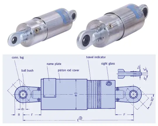
Working of Hydraulic Snubbers
Similar to an automobile shock arrestor the hydraulic snubber is built around a cylinder containing hydraulic fluid with a piston (See Fig. 2) that displaces the fluid from one end of the cylinder to the other.
Displacement of fluid results from the movement of the pipe causing the piston to displace within the cylinder resulting in high pressure on one end of the cylinder and relatively low pressure on the other.
The velocity of the piston will dictate the actual difference in pressure.
The fluid passes through a spring-loaded valve, the spring is used to hold the valve open. If the differential pressure across the valve exceeds the effective pressure exerted by the spring, the valve will close. This causes the snubber to become almost rigid and further movement or displacement is substantially prevented.
The hydraulic snubber is generally used when the axis of restraint is in the direction of the expansion/ contraction of the pipe. The snubber is therefore required to extend/ retract with the normal operation of the pipework. The snubber has low resistance to displacement/ movement at very low velocities. The resistance to normal thermal movements (pipe velocity less than 1 mm/Sec and with an amplitude of vibration less than 3 mm) is less than 2% of the rated load of the snubber.
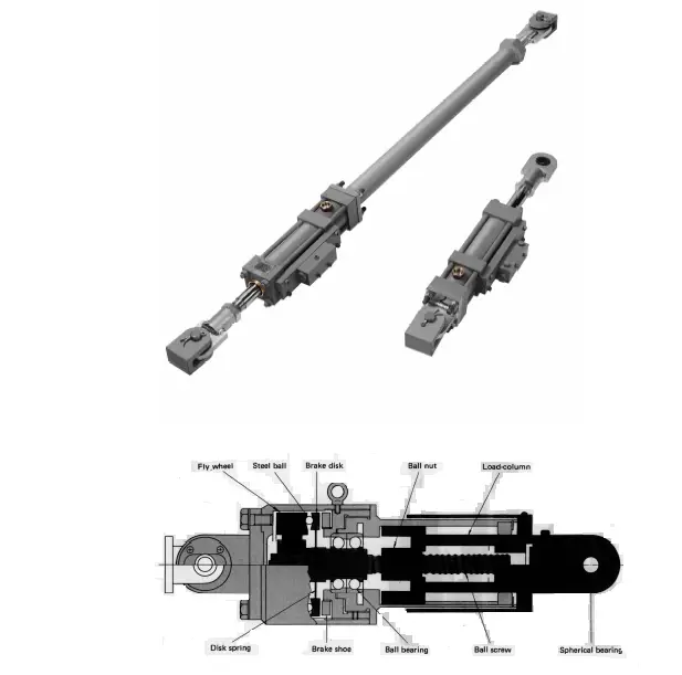
Working of Mechanical Snubbers
Whilst having the same application as the hydraulic snubber, retardation of the pipe is due to centrifugal braking within the snubber. A split flywheel is rotated at high velocity which causes the steel balls to be forced radially outwards. The flywheel is forced apart by the steel balls causing braking plates to come together thus retarding the axial movement/displacement of the snubber. Rotation of the flywheel is generated by the linear displacement of the main rod acting on a ball screw or similar device.
Mechanical snubbers (See Fig. 3) are used in cases of applications where human access is restricted, for instance, due to the high radiation atmosphere in the nuclear plant or due to a high elevation point where no scaffold is available & maintenance work is not easy to do. No maintenance service is required for mechanical snubbers & are designed to generate the required resistance force instantly on reaching threshold acceleration, to restrain a displacement of piping caused by an earthquake or other dynamic events & resume their free movement as soon as the dynamic displacement is suppressed while developing very little (a negligible level of) frictional resistance force during the slow thermal displacement mode of piping.
Selection of Snubbers
The snubber is influenced by the same factors that the rigid strut is, the magnitude and direction of axial force, but it is also necessary to consider the thermal displacement the snubber has to undergo.
Again it is necessary to use trigonometry for calculating the force and the length of the snubber along with the actual displacement applied to the snubber. Displacements in the primary axes cannot be combined simply to determine the snubber movement/displacement; it is necessary to calculate the overall length of the snubber in the various installed and operating conditions in order to determine the needed stroke.
After calculating the actual stroke it is good engineering practice to take a margin of excess travel at each end of the design travel. So, Always select a snubber that is capable of allowing greater displacement than is theoretically required.
Orientation of the snubber is also important for both hydraulic and mechanical types. Access to either lubrication points or inspection points is normally required and must be considered during the design and installation of the restraint. It may also be required to allow in-situ testing of the snubber for validating its functionality and so access may be a permanent requirement.
For selecting the proper Snubber, determine the minimum required stroke by taking the anticipated design movement and adding an allowance for excess travel. This allowance should normally be at least 20% of the anticipated design movement. Then select a snubber where the cylinder stroke is greater than or equal to the minimum required stroke and the applied loadings in tension and compression are less than the allowable maximum loadings in tension and compression for the size and length of snubber as shown in the catalog. For intermediate lengths, allowable compressive loadings may be determined by interpolation. The length of the snubber must be such that the maximum angulations are not exceeded.
To calculate the required closed centers for the snubber, use the following formulae:
Closed Centres = Installed Centres — X
Where X = (Stroke – Design Movement in Extension) / 2 or
X = (Stroke + Design Movement in Compression) / 2
This method will result in spare travel being distributed evenly on either side of the design movement.
Main Application of Snubber
Snubbers are normally used for reducing the damaging effects of Earthquake events.
Click here to check the modeling of snubber in Caesar II
Online Course on Pipe Support Engineering
If you want to learn more details about pipe support engineering then the following online course is a must for you: