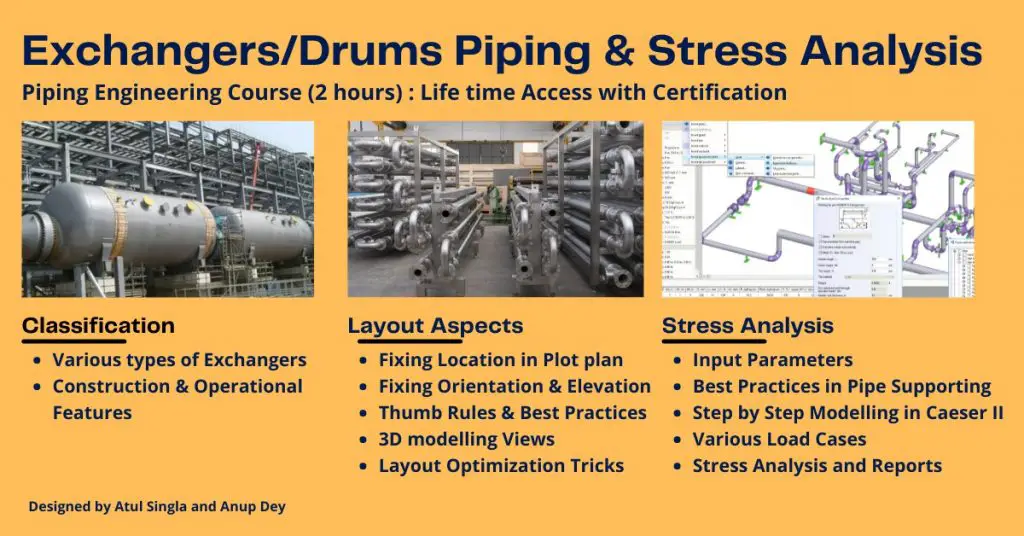
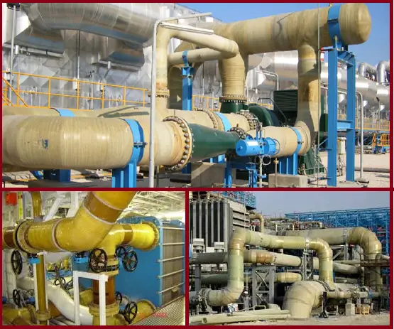
The scope of Piping Design
The scope of piping design refers to the entire design process of connecting the equipment using appropriate piping components as determined by the process engineering team. It’s comparable to the human body; piping is equivalent to the veins that connect the main organs together.
The basic elements of Piping Design
The main aim of the piping design is to lay equipment, piping, and other accessories meeting the relevant standards, statutory regulations, and safety requirements. Of course, there are other aspects as described below.
Plant Layout
- Safety: Fire, Leakage, Easy escape, safety showers, eyewash
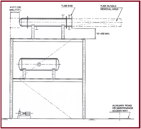
- Maintainability & Operability: Dropdown zone, crane, fork-lift, hose station, platform, ladder, stair
- Cost: Economic layout (equipment/ piping), optimization of materials
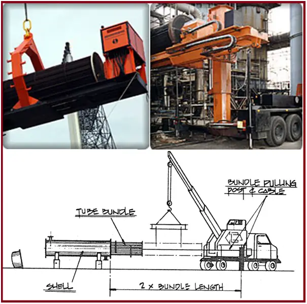
- Constructability: Transporting and erecting large equipment, space for fabrication, the sequence of construction
- Others: Weather conditions, Wind Direction, Location, Relevant regulations, Product in/out, Utilities and drain location, Conditions around battery limit, Area for future expansion
First Piping Engineers produce Site Plan, then they develop the overall Plot Plan and Unit Plot Plans. After Unit Plot Plans are in place, They develop major piping in and around equipment. They do plan for pipe racks as well.
- Pipe routing studies and Nozzle /platform/ladder orientations are developed.
- Underground piping is given priority as the construction starts from underground.
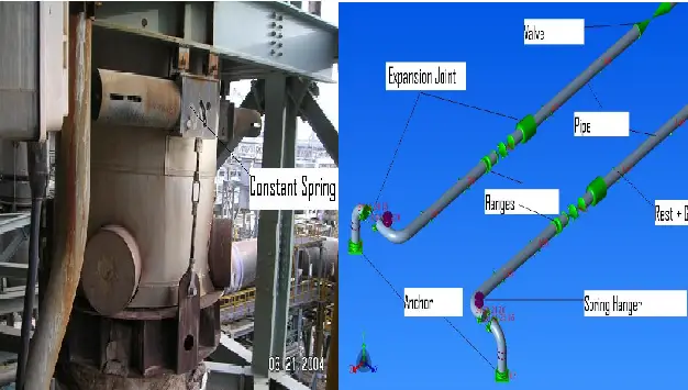
- Based on the size, temperature, pressure, flow type, and equipment type to which the line is connected, we identify lines to be Stress Analyzed. We perform Stress Analysis using software like CAESAR II, AutoPIPE, etc.
- Pipe Routing Studies
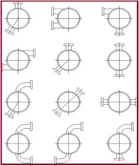
- Equipment Nozzle Orientation:
Underground Piping
Underground piping refers to pipes that are buried underground and it aims to optimize the design and construction processes of a plant by finding the most effective connection between each process and different utilities.
Scope of Underground Piping:
- Underground piping routes (e.g. cooling water, sewer piping, trench piping)
- Equipment foundation location
- Underground electrical and instrument routes
- Civil/structure-related information
- Road layout, etc.
Water Hammer Analysis:
What is Water Hammer?
The rise or fall in pressure caused by changes in the volume of fluid must be analyzed and applied precisely to piping design. In general, such changes in water pressure are generally known as water hammer but to be precise, hydraulic transient would be more correct. Such changes in pressure produce noise, vibration, shock, etc., which can result in the breakdown of the equipment and piping.
Main Purpose of Water hammer Analysis
- To determine the economic wall thickness of large-bore and long-distance pipelines
- To determine the design and location of the required equipment (e.g. accumulator, surge tank, by-pass line) to avoid hydraulic transients
- To determine the valve closing time and schedules
- Click here to know more details about pressure surge or water hammer analysis
3D Modeling and Review
3D Model: Graphic data of various structures, equipment, piping, cables, and building parts of a plant displayed in virtual space using 3D CAD.
Model Review: A process carried out in-appropriate design stages to examine whether the developing work is meeting the requirements of the client and recommended design standards. It is also done to understand and provide solutions for problems in the design.
Purpose of Model Review:
Client’s Perspective
- To ensure a quality product
- To ensure safety
- To examine operability
- To examine repair/maintenance
- To examine environmental impacts
Engineering Company’s Perspective
- To meet the client’s requirements
- To prevent design errors
- To achieve better drawing quality
- To follow drawings and construction schedules
- To improve earnings and provide client satisfaction
Stages of Model Review:
- 30% Model review: Review from a plot plan point of view – location, installation, construction, maintenance, and repair of the equipment
- 60% Model review: Review from an operation point of view – process requirements, tray routes for piping. Also, make appropriate changes from the 30% review. Major Line Routing reviewed and finalized.
- 90% Model Review: Overall review aimed at producing the final drawings. Make appropriate changes from 30% and 60% Model Reviews.
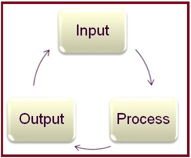
Required Input for Piping Design: Workflow
- Required Input: It ranges from PFD/P&ID, Line List, Data Sheets, and Vendor Prints to the various deliverables of other disciplines like Structural Arrangement Drawings, Cable Layout, Level sketches of Instrumentation, etc.
- Piping Activities: Preparing Site Plan, Overall Plot Plan, Unit Plot Plan, Nozzle Orientation, Rack sizing, Equipment/ Piping modeling, Laying outlines, Job instruction, Project Specification, Materials Take Off (MTO), Stress Analysis, etc.
- Piping Outputs: Site Plan, Overall Plot Plan, Unit Plot Plan, Nozzle Orientation, Complete 3D model, Isometrics, Pipe MTO, Project Specifications, Piping GA drawings, Special Pipe Support Index/ datasheet, Support MTO, Insulation/ Paint MTO.
It’s an IPO cycle as shown in figure (Fig. 1) below:
Importance of statutory requirement in piping design
Statutory and Regulatory Requirements in Piping Designs….
- When a plant is set up in any country, its design is governed by the statutory and regulatory requirements of that country. Some examples are as follows:
- Petroleum and Explosive Safety Organisation (PESO): With an overall objective of ensuring the safety and security of public and property from fire and explosion, PESO as a statutory authority is entrusted with the administration of the Explosives Act, 1884, Petroleum Act, 1934; Inflammable Substances Act, 1952 and other related acts.
- Oil India Safety Directorate(OISD): e.g. OISD-STD-118-Layout for Oil & Gas Installations, OISD-STD-117- Fire Protection Facilities for Petroleum Depot/ terminals, etc.
- Indian Boiler Regulation (IBR): IBR approval is required for IBR equipment and lines.
- Environment /Pollution related Norms: Also to be complied with such as allowable emission rate of NOx, SOx
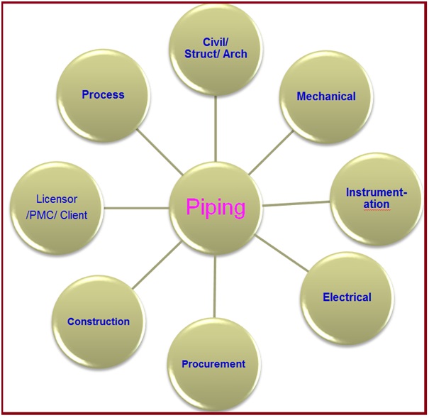
Internal and External Coordination in Piping design
As the work of piping design tends to overlap with that of Process, Mechanical, Civil/Architecture, Electrical, Instrument engineering teams, and others, it is important for a piping engineer to work in close coordination with related departments all the while maintaining a broad and comprehensive view of the plant.
- The process is the upstream discipline for the engineering group. The process provides PFD, Process Data Sheets, P&ID, Equipment List, Line List, etc.
- The mechanical group gives us the Mechanical Data Sheet of Equipment. In the later stages of design, Vendor Prints (VPs) are made available.
- The Civil/ Structural/ Architectural group provides the required foundation for equipment, structures for racks/ equipment, underground trenches, pits, structures for Miscellaneous Pipe Supports, etc.
- The instrumentation group supplies the data for inline and online instruments, control valves, and relief valves.
- Electrical gives the hazardous area classification drawings, cable layout, etc.
- All these disciplines are also involved in preparing the Plot Plans
- The piping design has enormous implications for plant construction, operation, and function.
- Construction and Procurement may be an internal/ external group depending on the project scope
- The most important external group to be coordinated with is the Client.
- There are other external groups such as the Licensor and the PMC. They are equally important. ITB to be thoroughly read to understand the PMC requirement and the Licensor requirement.