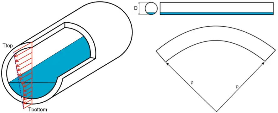
The thermal bowing phenomenon occurs when a horizontal pipe is filled partially by hot or cold fluid (LNG). Many thermal bowing occurrences cause unexpected damage to the piping or supporting structure. Since thermal bowing occurs mostly at transient conditions, such as during startup, the bowing phenomenon may go unnoticed until the damages are discovered.
It can also occur when one side of the pipe is exposed to the sun and the other side is in the shade.
This effect takes place when the temperature difference between the top and bottom of the pipe section is significant. It is called the thermal gradient. This thermal gradient causes pipe thermal strains that produce pipe curvature called thermal bowing.
Assumptions for thermal bowing
The following Assumptions are made for thermal bowing
Thermal strain distribution across the pipe section is linear
Applied only for horizontal pipes that meet “horizontal tolerance” criteria |DZ| / ( DX2 + DY2 + DZ2 )0.5 < Tolerance
Bowing is acting only in the vertical plane
Basics of Thermal Bowing
The thermal gradient can be different for each pipe element. And also it can be different in each operation mode.
Temperature Distribution in Thermal Bowing
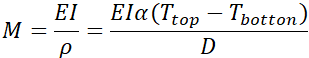
The pipe curvature due to the thermal bowing effect:
r – curvature radius D – outside diameter of the pipe a – thermal expansion coefficient at operating temperature
Ttop – the temperature at the top of the pipe Tbottom – the temperature at the bottom of the pipe
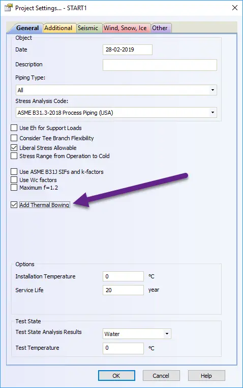
Performing Thermal Bowing in Start-Prof
The thermal gradient (Ttop-Tbottom) should be specified in pipe properties.
Specifying Thermal Bowing in Start-Prof
The thermal bowing effect should be switched on in Project Settings.
Switching on Thermal Bowing Effect
The bending moment produced in the restrained pipe due to the thermal bowing effect:
E – pipe elastic modulus at operating temperature I – the moment of inertia
The operating temperature should be equal to (Ttop+Tbottom)/2
EOT (Electric Overhead Traveling) Cranes and Hoist are industrial machines that are mainly used for materials movements in construction sites, production halls, assembly lines, storage areas, power stations, and similar places.
Types of Cranes
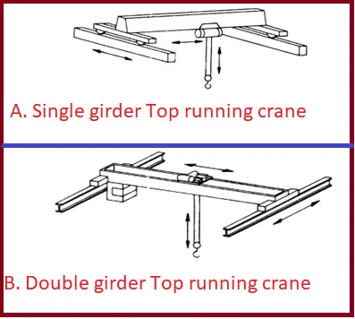
Single girder cranes (Fig. 1A) – The crane consists of a single bridge girder supported on two end trucks. It has a trolley hoist mechanism that runs on the bottom flange of the bridge girder.
Double Girder Bridge Cranes (Fig. 1B) – The crane consists of two bridge girders supported on two end trucks. The trolley runs on rails on the top of the bridge girders.
Fig. 1: Figure showing single and double girder cranes
Selection of Cranes
Which Crane should you choose – Single Girder or Double Girder
Generally, if the crane is more than 15 tons or the span is more than 30m, a double girder crane is a better solution.
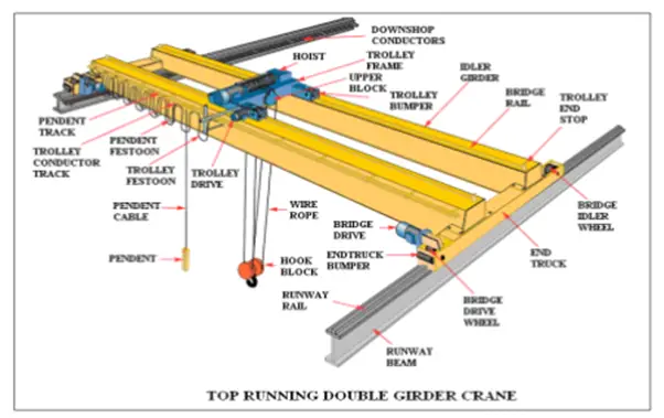
Components of Cranes (Fig. 2)
Fig. 2: Figure showing Crane Components
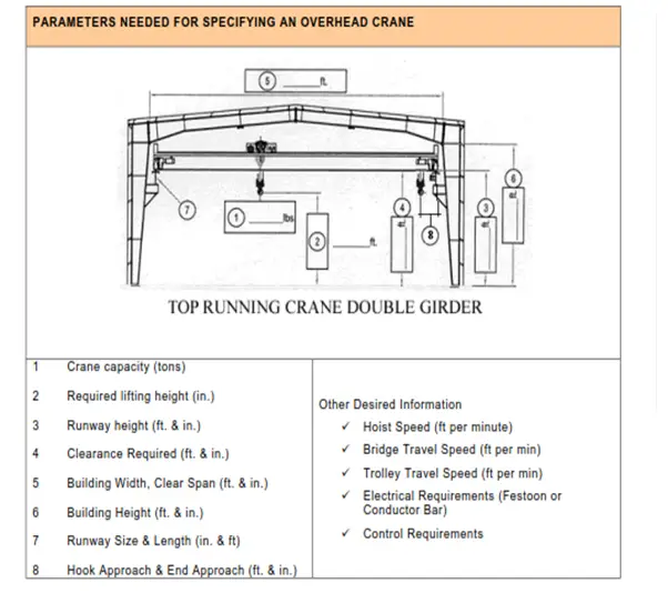
Essential Parameters for Specifying EOT Cranes (Fig. 3)
Fig. 3: Parameters needed for specifying an overhead crane
Codes and Standards for EOT Cranes
Electric Overhead Traveling cranes shall conform in design, materials, construction, and performance with the current issue of the following specifications, codes, and standards.
CMAA 70 Specification for Top Running Bridge & Gantry Type Multiple Girder Electric Overhead Traveling Cranes
AGMA American Gear Manufacturer’s Association
ASME HST-4 Performance Standard for Overhead Electric Wire Rope Hoists
ASME Y 14.1 Decimal Inch Drawing Sheet Size and Format
ASME B18.2.2 Square and Hex Nuts
ASME B30.2 Overhead and Gantry Cranes (Top Running Bridge, Single or Multiple Girder, Top Running Trolley Hoist)
ASME B30.10 Hooks
AWS D14.1 American Welding Society – Specification for Welding of Industrial and Mill Cranes
HMI 100-74 Hoist Manufacturer’s Institute – Specification for Electric Wire Rope Hoists
NEC 610-14 Determining Amperage Requirements for Cranes and Hoists
NEMA ICS 8 Industrial Control and Systems – Crane and Hoist Controllers
NFPA70 National Electrical Code
OSHA Occupational Safety & Health Administration
IBC International Building Code (This will eventually replace UBC)
UBC Uniform Building Code
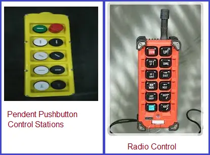
Control Equipment (Fig. 4) for EOT Cranes
Fig. 4: Typical control equipments for crane
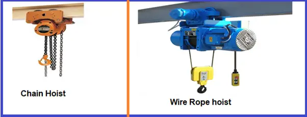
HOISTS (Fig. 5)
A hoist is a device used for lifting or lowering a load by means of a drum or lift wheel around which a rope or chain wraps.
Fig. 5: Figure showing typical Hoists
Hoist Selection Factors
The weight of the load to be lifted includes below-the-hook lifting, load-supporting, and positioning devices.
The physical size of the load.
Clearance Considerations
Lifting Speed Considerations
Hoist duty
Hoisting Equipment
Sheaves
Hook Assembly
Gear Assembly
Rope Drum
Ropes
Hoist Standards
ASME-HST-1 Performance Standard for Electric Chain Hoists
ASME-HST-2 Performance Standard for Hand Chain Manually Operated Chain Hoists
ASME-HST-3 Performance Standard for Manually Lever Operated Chain Hoists
ASME-HST-4 Performance Standard for Overhead Electric Wire Rope Hoists
ASME-HST-5 Performance Standard for Air Chain Hoists
ASME-HST-6 Performance Standard for Air Wire Rope Hoists
ASME-B30.7 Safety Standard for Base Mounted Drum Hoists
ASME-B30.16 Safety Standard for Overhead Hoists (Underhung)
ASME-B30.21 Safety Standard Manually Lever-Operated Hoists
OSHA (Parts 1910 and 1926) adopts or invokes the American Society of Mechanical Engineers
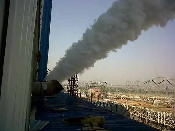
Prior to commissioning, it is essential to thoroughly clean the internal surfaces of pipes. This cleaning process, known as steam blowing, is used to remove rust, dust, scales, and debris. If this procedure is not executed properly, it can lead to significant damage or a shortened lifespan of critical components such as steam traps and control valves.
Steam blowing is a critical process used primarily in the commissioning and maintenance of steam systems. It involves the use of high-pressure steam to clear out impurities and debris from the pipes of a steam generation system, ensuring the system operates efficiently and safely. In this blog post, we’ll delve into the fundamentals of steam blowing, its purpose, procedure, benefits, and key considerations.
What is Steam Blowing?
Steam blowing, also known as steam flushing, is a method employed to clean the internal surfaces of steam pipelines and equipment. It is most commonly used in power plants, petrochemical facilities, and other industrial applications where steam systems are prevalent. The primary goal of steam blowing is to remove any residual debris, welding slag, mill scale, or other contaminants that might obstruct the flow of steam or cause damage to the system.
Steam blowing is one of the initial cleaning operations before starting any power plant or steam lines. Steam blowing of MS lines, CRH, HRH, SH, RH, HP, & LP bypass pipelines of the turbine is carried out in order to remove welding slag, weld bead deposits, loose foreign materials, iron pieces, rust, etc. from the system, generated during manufacturing, transportation, & erection prior to turbine operation. The cleaning is accomplished by subjecting the piping systems to heating, blowing steam, and cooling cycles in sufficient number and duration until clean steam is obtained.
Why is Steam Blowing Necessary?
During the construction or maintenance of steam systems, particles, and debris can accumulate inside the pipelines. These contaminants can originate from welding processes, pipe manufacturing, and even the installation phase. If not removed, these particles can lead to:
Reduced Efficiency: Blockages or restrictions in the pipes can reduce the efficiency of steam flow, leading to higher energy consumption and operational costs.
Equipment Damage: Debris can cause erosion, corrosion, and damage to critical components such as turbines, valves, and heat exchangers.
Safety Risks: Inadequate cleaning can increase the risk of operational failures, which may lead to safety hazards, including potential explosions or leaks.
Working Principle of Steam Blowing
The working principle of steam blowing involves using high-pressure steam to clean and clear debris from pipelines and equipment. The process begins with the generation of steam at high pressure and temperature from a boiler or steam generator. This steam is then directed into the pipeline or system through specialized blow-off connections. The high-velocity steam creates dynamic pressure within the pipes, which effectively dislodges and carries away contaminants such as rust, dust, scales, and welding debris.
As the steam flows through the system, it sweeps out impurities by exerting significant force, thereby ensuring that the internal surfaces of the pipes are thoroughly cleaned. This process not only removes blockages that could impede the flow of steam but also helps prevent potential damage to critical components like valves and turbines. Proper monitoring and control of steam pressure and flow are essential to ensure the effectiveness of the cleaning and to maintain safety throughout the operation.
The effect of Steam Blowing depends on the following factors:
Thermal shock
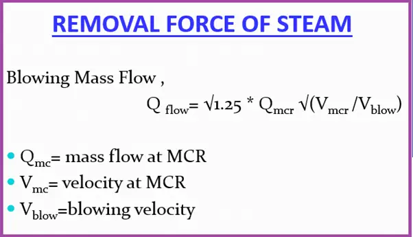
Removal force of steam
Cleaning force of steam
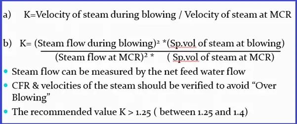
Cleaning Force Ratio or CFR of Steam Blowing
The necessity to create in the system, a steam velocity greater than that is possible at MCR condition is obvious. These two velocities are expressed as a ratio “Cleaning factor” or “ Distribution factor” or “Cleaning Force Ratio” denoted by “X” or “K”.
CFR (Cleaning Force Ratio) is also known as Cleaning Factor or CF. CFR is an industry-accepted factor that determines the required dynamic pressure. CFR in steam blowing can be defined as the ratio of required dynamic pressure for cleaning to maximum dynamic pressure experienced during system operation.
Cleaning Force required (CFR) or distribution Factor
Preconditioning for Steam Blowing
Chemical cleaning should be completed.
SH’s primary and secondary de-superheater piping and RH’s emergency de-superheater piping ready for operation
All permanent piping & temporary piping insulated and supports/hangers are released with a cold setting
The silencer should be connected at a temporary pipe exit
Soot blowing for APH should be available
Makeup for the deaerator made ready
Motor-Driven BFP with all controls made ready
Hydraulic test of the following lines completed:
Feed Lines
MS, HRH, CRH Lines
MS to Aux. PRDS Line
All other auxiliary lines identified for steam-blowing
The sampling system made ready
Boiler auxiliaries proved serviceable and ready after a pilot operation like:
Fuel oil system
Compressors & Atomizing steam system
Start-up system ( for the continuous system)
Coal Mill system (for the continuous system)
CHP readiness
Economizer hopper and bottom ash hopper and its evacuation system (for the continuous system)
All safety valve discs installed after removing the hydro-static plugin drum(sub-critical), superheaters, and reheaters
Adequate communication between the control room, boiler, and TG are ensured.
Flow nozzle, control valves, and NRV flaps wherever applicable should be not erected before steam blowing and suitable spool pieces are erected. Strainers in the path should be removed.
Required number of Target Plates and holders made available
ACID CLEANING ( BY CITRIC ACID METHOD )will be done by the circulation method for the effectiveness of the cleaning process.
Acid cleaning will be followed by PASSIVATION so that the uniform protective coating of GAMMA FERRIC OXIDE is formed on the metal surface and corrosion/oxidation damage to the metal surface is prevented and continues during normal operation by dosing oxygen. The gamma ferric Oxide formed by using the chemical 1-2 % sodium Nitrite(NaNO2)
Steam Blowing Procedures Techniques
Normally, two methods are historically used for steam-blowing
PUFFING METHOD
PURGING METHOD / CONTINUOUS BLOW METHOD
PUFFING Method of Steam Blowing
To give a thermal shock to the contour being purged, to dislodge the scale, etc.
Procedure: Raise the boiler pressure to a pre-determined value (40-60 kg/cm2), shut off firing, and at the same time open the quick opening valve(EOTV), thus allowing the steam to escape to atm. with high velocity carrying with it the loose debris.
Precautions during the puffing method
The Pressure drop allowed in the drum is limited to the corresponding saturation temp. change of 40 OC.
Scheme of puffing method
Steam blowing done in stages
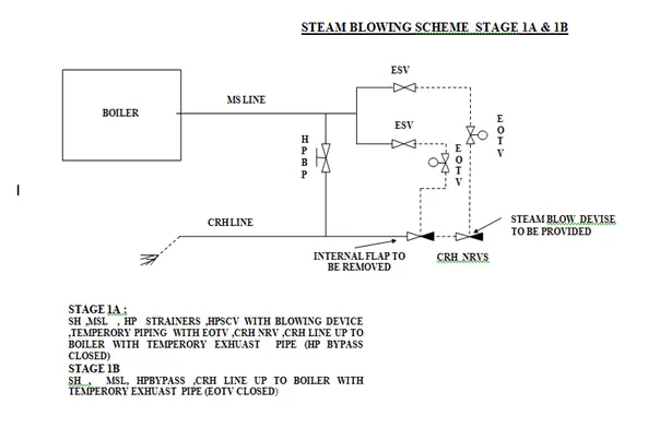
Stage-1(a):
SH, MSL, ESV, temporary lines from ESV to EOTV, EOTV to CRH line, CRH lines up to boiler end with the temporary exhaust pipe.
Tap-off lines from CRH to deaerator, auxiliary PRDS, HP heater 6a & 6b, gland sealing, etc. shall remain closed/isolated.
Stage 1a endpoint will be concluded by observing the indents on the target plate.
Stage- 1(b):
SH, MSL, HP bypass interconnection, hand-operated valve mounted in place of HP bypass valve, and CRH lines up to Boiler end with temporary exhaust piping.
In this stage, 6 to 8 blows will be given through HP bypass lines to ensure the cleanliness of the limb.
The boiler MS stop valve will be used for stage 1b. EOTV will be kept closed. Manually Operated Isolation Valves in HP bypass lines will be kept open fully.
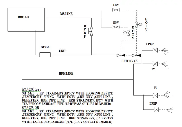
Stage-2(a):
1a plus reheater, HRH lines, Interceptor Valve, and temporary pipe.
CRH line along with the attemperator shall be welded with a reheater before the start of stage 2a. LP bypass lines shall be blanked during stage 2a. Stage 2a endpoint will be concluded by observing the indents on target plates
Stage- 2(b):
2a up to IV + LP bypass lines with the temporary exhaust pipe.
Stage 2b blowing will be a parallel blow in paths 2a & 2b. LP Bypass blanks shall be removed for stage 2b. 4 blows will be given through the L.P. Bypass line to ensure the cleanliness of the limbs
Stage-3:
Auxiliary Steam Lines covered in steam blowing are listed below.
3a) Main steam line to Aux PRDS
3b) CRH to Deaerator
3c) CRH to HPH-6.
All auxiliary steam lines will be steam blown by the continuous blowing method
Stage-4:
The following Aux steam lines, connected to the deaerator are steam blown using auxiliary steam from the Auxiliary PRDS header.
4a)PRDS to Deaerator.
4b)Extraction 4 to
4c) PRDS to Gland steam header
Continuous Steam Blowing Procedure
The initial procedure is the same as the puffing method except:
Continuous firing till the completion of steam blowing. No need to shut off the firing during blowing.
Maintain constant pressure during the blow
Recommended blowing parameters for continuous steam blowing
Dynamic steam pressure = 3.5 MPa
MS temp = 420(not to exceed)
HRH temp = 480( not to exceed)
Steam flow = 845 TPH
Corresponding Drum pr. = 40 Ksc
Furnace load ≈ 39%
Method of Continuous Steam blowing
Set the Temporary purging valve, by-pass valve, drain valve, and granulating device behind the temporary pipes
Check the tightness, support, and expansion of the temporary system
Section by section rinse of condensate water piping, feedwater piping, and boiler through the start-up system to the CW system
Circulation begins when Fe+ in the water of the main feedwater pipe and separator outlet will be less than 100 ppm.
Maintain the circulation flow or start-up flow at a minimum set value
Start oil firing and raise the temp and press. according to the cold start-up.
rise rate of water wall = less than 2OC / min
rise rate of main steam = 4 ~ 5 OC / min
Before MS press reaches 1.0 Mpa, open the bypass valve of the temporary purging valve to warm the piping with all water drain valves of the system open.
-The blowing system is divided into two parts
A) Preliminary Steam Blowing
B) Final Steam Blowing
Preliminary Cleaning
PURPOSE-
Primary cleaning out sundries and bulky grain deposited in the RH and main steam system
To ensure the fastness of supports and hangers with proper expansion
Know well about the operation property of the oil-burning system, condensate water, and feed water systems
Preliminary Steam Blowing Procedure
Start the oil firing with max. rating of 15%
Control the gas temperature at the furnace outlet below 500 OC (max.538OC )
Raise the SH outlet press to 1.6 – 1.8 Mpa with a steam temperature of around 350 OC.
Open the temporary purging valve for 15-20 min to blow in the MS system
Maintain K around 0.5.
SH & RH desuperheater water system also cleaned
Final Steam Blowing Procedure
The main steam and reheated steam system are purged in series
Start 2-3 coal mills when the oil burner hits the rated firing rate of 15%
Increase the SH outlet press. to 3.5 Mpa.
Maintain the MS temp < 420 OC.
Keep HRH steam temp around 480 OC.
When the steam line blowing parameter reaches, open the temporary purging valve gradually and increase the fuel and feed water volume to sustain parameter stability.
Establish the MS flow around 40% of the MCR (max.- 50%)
Ensure CFR (K) should be 1.25 to 1.3 for MS and 1.05 to 1.1 for reheated steam
Blow under this operating condition for 20 to 30 min
Gradually reduce coal firing and close the purge valve at 0.5MPa.
Remove the target plate and check it
By estimation, the target may satisfy the requirements after 15 to 20 times in-series purging
When the steam line temp is above the sat. temp of MS press, close all drains and Open the boiler MSSV fully.
Maintain the press. through controlled firing
Insert a reference target
Check the CFR
Allow running for 30-60 min
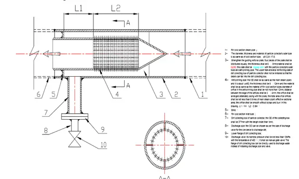
Target Plate in Steam Blowing
Generally Stainless steel panel
Target plate set at the first, sixth, ninth, and twelfth purging, thereafter, set a target for each purging until purging results qualified.
Width about 8% of the steam vent tube inner diameter (ID) and length equal to the ID
Brinell hardness < 90
Steam velocity – 258 m/sec
Target plates are to be introduced just before steam blowing/light up—to be removed soon after blowing is completed.
Online Target Plate Change Arrangement
Debris Filter
Steam Blowing Completion Criteria
At least 2 continuous target plates should not have ORIFICE GRANULARITY on the target and shall be no larger than 0.8 mm.
CFR should be 1.25 to 1.4 of an orifice, granularity shall not surpass 08 nos.
Determining Cleanliness After Steam Blowing
To assess the cleanliness of a piping system after steam blowing, “target plates” are used. These plates, typically made of aluminum or copper, help gauge the effectiveness of the cleaning process. The evaluation involves three key steps:
Placement and Impact Assessment: Position target plates at the outlet points of the main piping system during the steam blowing operation. Assess the impact on these plates to evaluate the cleaning action.
Evaluation of Results: The cleaning process is deemed effective if two consecutive target plates show fewer than two pits per square inch, with each pit having a maximum diameter of 0.3 mm.
Reinstallation and Recommissioning: After steam blowing, reinstall any removed steam traps and other equipment. Following these steps, the piping system can be reheated and recharged for operational use according to its intended purpose.
Advantages of Steam Blowing
Required less time for completion of the total process
Less time is required to normalize the system for final light-up to synchronization
This reduces the reactionary forces on the temporary pipes
Stresses on the boiler system are lower
Comparison between Puffing & Continuous Method of Steam Blowing
PUFFING METHOD
CONTINUOUS METHOD
— More time is required for complete steam blowing due to stage-wise blowing(8-10 days) — More time is required for stage-wise temporary pipe erection and shifting of the blowing device — No mill required — Quality of cleanliness is better than a continuous process — Thermal shock is the driving force behind cleaning — More thermal stress on tube material and sudden loading on supports — Repeated light-up and shutdown — There is a time gap between the blows to make up DM water — System normalization time after steam blowing is more — Silencer use is optional
— Less time required for completion (3-4 days) — Less time is required as only valves are to be opened for different systems — Minimum 02 nos. of mill required — The quality of cleanliness is slightly less than Puffing. — Steam velocity or Removal force is the driving force — Less thermal stress on tube material — Light up only once at the beginning of the steam-blowing — DM water makeup to the system during steam blowing is a challenge — System normalization time after steam blowing is less. — Silencer use is compulsory.
Difference Between Puffing and continuous Method of Steam Blowing
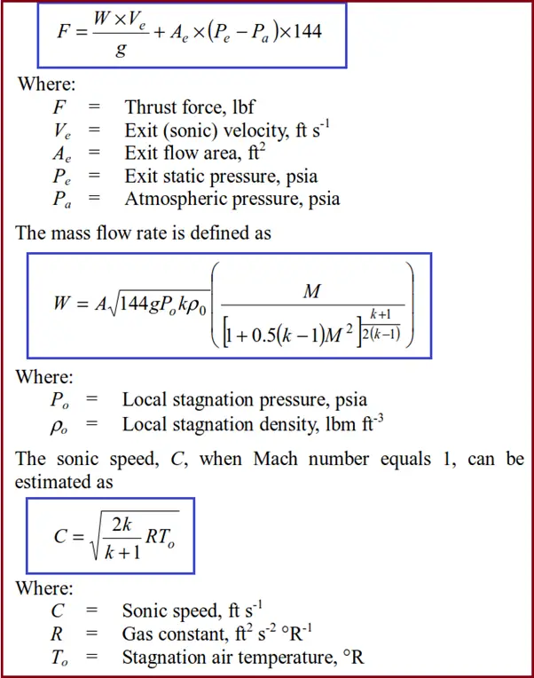
Calculation of Steam Blowing Thrust force at the end of Pipe Exit
The thrust force (F) of the jet at the pipe exit is estimated as
Steam Blowing Thrust Force Calculation
Hazards of Steam Blowing
Steam blowing poses several hazards, primarily due to the high-pressure steam used in the process. The intense force of the steam can cause severe burns, injuries, or fatalities if proper safety precautions are not followed. Additionally, the sudden release of steam and debris can create dangerous projectiles and high noise levels, which can further pose risks to personnel. The high-pressure environment also presents risks of equipment failure or malfunction, potentially leading to catastrophic failures or explosions if the system is not properly maintained and monitored. Implementing stringent safety measures, including protective gear, safety barriers, and thorough training, is crucial to mitigating these hazards and ensuring a safe steam-blowing operation.
Pipe Expansion Loops on the Piping or Pipeline Systems
Expansion loops are fundamental in various piping industries involving higher temperatures including oil and gas, chemical processing, power generation, and HVAC systems, where temperature fluctuations can cause significant stress on piping networks. Even in pipeline systems where the length of the pipe is greater, expansion loops play a significant role in proper design even though the temperature is not higher. One of the most common methods used to manage thermal expansion in piping and pipeline systems is the expansion loop.
Why do we need Piping Expansion Loops?
Piping systems are often subjected to varying temperatures, either due to the fluid being transported or environmental conditions. As the temperature of a material increases, it expands, and when the temperature decreases, it contracts. This expansion and contraction can result in significant stress on the piping material.
All piping engineers are well acquainted with expansion loops in the piping systems. Whenever thermal displacements are more than a certain value these expansion loops are added to absorb the displacement inside the expansion loop. These are mainly required in any piping system design to
Reduce system stress,
Limit thermal displacements, or
Limit Support Loads.
How Piping Expansion Loops Work
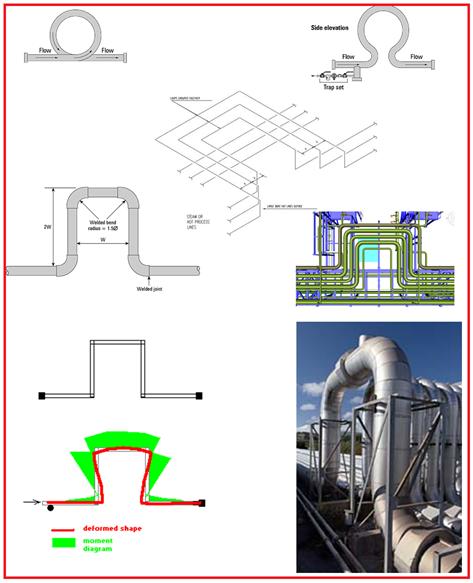
An expansion loop is a section of pipe that is intentionally bent into a U-shape, Z-shape, or similar configuration (Refer to Fig. 1) to absorb the thermal expansion and contraction of the pipeline. By introducing flexibility into the system, expansion loops allow the pipe to expand or contract without causing undue stress on the pipe or surrounding supports and structures.
Piping expansion loops are used to increase the flexibility of the piping system. To reduce the generated expansion stress and displacement caused by thermal expansion or contraction, legs perpendicular to the main piping system are provided. This perpendicular length is known as the length of the expansion loop. The more this expansion loop leg length, the better for the piping system. However, this leg length is limited by support feasibility, vibration tendency, and cost. That is the reason the length of the absorbing leg in an expansion loop is decided only to meet the requirement of stress qualification.
Piping expansion loops are widely used in long runs of pipes running over the pipe racks or sleepers. Pipeline expansion loops are usually provided at every 500 m length as the design temperature of pipelines is normally less as compared to piping systems.
Fig 1 shows typical loops used in the piping system.
Fig. 1: Typical Expansion loops
Functions of Piping Expansion Loops
Expansion loops serve various purposes as listed below:
Piping Expansion Loops provide the necessary leg of piping in a perpendicular direction to absorb the thermal expansion. They are safe when compared with expansion joints but take up more space.
Load due to axial expansion causes bending stresses to be developed, increasing upwards in the vertical pipes and becoming a maximum at the loop elbows.
That bending moment stays at that maximum bending moment level for the entire length of the top horizontal pipe until it gets to the next elbow and starts’ reducing until it reaches the bottom pipe on the other side of the loop.
As the loop gets higher, both axial resultant stress in the horizontal pipes and the bending moments in the loop are reduced.
Types of Piping Expansion Loops
Piping Expansion loops are categorized into different styles:
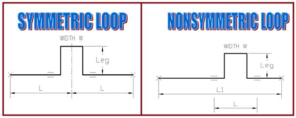
1. Symmetric loop vs Nonsymmetric loop (Fig. 2):
Ideally, loops shall be located centered between pipe anchors with equal legs on either side of the anchor. Symmetrical loops are advantageous in absorbing an equal amount of expansion from both directions.
When this isn’t practical make legs on either side of the anchor as equal as possible.
Friction Forces are determined by the number of pipes supporting a line crosser. By making these legs equal, the forces at the anchor should remain nearly balanced.
Fig. 2: Symmetric and non-symmetric loops
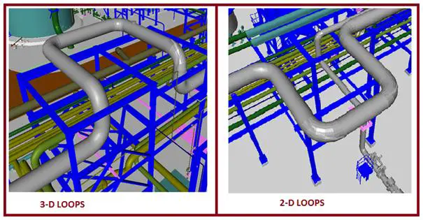
2. 2-D vs 3-D Expansion Loops (Fig. 3)
Expansion Loops may be 2-D (Two-dimensional loop) or 3-D (three-dimensional loop) types. Normally for steam lines, flare lines, condensate lines, and sloped lines, where there is the possibility of two-phase flow, 2-D expansion loops are preferred. Otherwise, the 3-D loop can be provided.
Fig. 3: 2-D vs 3-D Loops.
Requirements of Multiple Expansion Loops
More than one expansion loop may be required when:
It is impossible to make branch connections flexible enough.
Spacing between branches and neighboring lines or steel is limited.
When the loop becomes too large to support or fit into the space available.
Anchor forces become too unbalanced and steel cannot be economically braced.
More than one expansion loop may be required when the forces required to bend the loop are too great, and the anchors cannot be economically reinforced.
When the thermal displacements exceed the project’s specifically allowed displacements.
When the length of shoe supports due to high thermal displacement is becoming too high it looks odd.
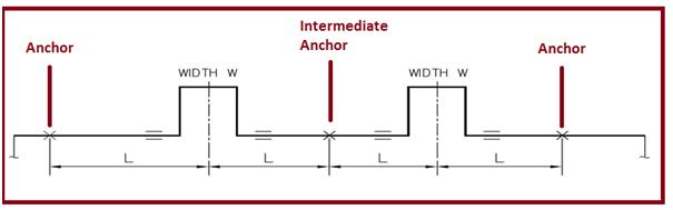
Fig. 4: Multiple Expansion loops in a piping system
Loop width should always be based on utilizing existing supports.
Thermal expansion must be allowed when spacing adjacent loops.
Loop width does not have to be near 20 feet just because the loop nomographs happen to use that number. Loop width has only a secondary effect on results.
Minimum loop height depends on the berthing of the line with respect to the location of the loop support.
Piping Expansion Loops cannot extend too far beyond existing support or the overhang will cause the loop to “lose its balance.” This sets the maximum allowable loop height.
The first two points have more influence on loop design than stress formulas, from the piping point of view.
Three-dimensional expansion loops are widely used because this arrangement does not block the routing of low-temperature lines under the loop.
Vertical loops are placed at road crossings and sometimes are nonsymmetrically located due to the location of the road.
Method for Sizing Pipeway Expansion Loops
Anchor lines near their center to determine which lines require loops by checking the allowable expansion at each end of the run. If the thermal displacement at each end is within the project-specific limit and will not clash with other lines, no expansion loop will be required. However, if the line spacing cannot be adjusted to take the movement, expansion loops need to be added.
Determine which of the lines requiring loops need the largest loop, second largest, etc., by the following:
Multiply the total expansion of each line between its proposed anchors by the pipe’s moment of inertia (E). (The stiffness of a line is measured by its “Moment of inertia.”).
The line with the largest of these calculated numbers will require the largest loop, the next smaller number, the next smaller loop, etc.
The above rule does not check stress. This is checked after the loops are roughly dimensioned.
Fit the expansion loops between two pipe supports using the minimum spacing plus allowance for line expansion and bowing. Make the loops as wide as possible, but keep the height to a minimum. If stress or force is extremely high, check with the stress engineer for the height of the loop.
Send finished pipe way to stress for accurate calculation of anchor forces for transferring to Structural and accurate evaluation of stresses in the piping.
Estimating Expansion Loop Leg Requirement / Expansion Loop Calculator
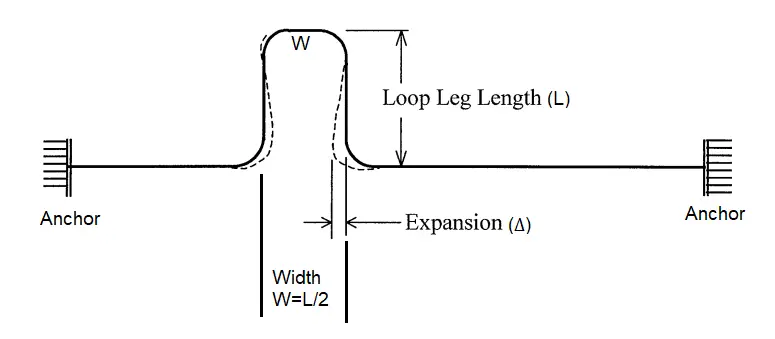
A preliminary estimate of the expansion loop absorbing leg requirement can be made from the equations derived from the guided cantilever method. As per that formula, the required absorbing leg, L (Refer to Fig. 5) for the piping expansion loop is given by
L=√(3ED∆/S)
where E=Elasticity modulus, D=Pipe OD, S=Allowable Stress at the maximum temperature, and ∆=thermal expansion.
Fig. 5: Piping Expansion Loop Leg Requirement
Providing an expansion loop in a piping system needs additional space and additional elbows (additional cost) which may not be possible in some instances. In such a scenario piping expansion joints are used to absorb the thermal growth.
I have created an expansion loop calculator for preliminary loop sizing using the above-mentioned formula which can be downloaded by clicking here.
Now that you have studied all the relevant sections regarding piping and pipeline expansion loops above, it is time to learn the following frequently asked questions:
What is a piping or pipeline expansion loop?
A piping or pipeline expansion loop is used in the systems to control the thermal expansion and contraction of pipes due to temperature variations. An expansion loop consists of bends/elbows and pipe sections designed in a specific way to absorb the movement and prevent stress on the piping system. They are usually located between two pipe anchors or buried parts in the aboveground piping/pipeline system.
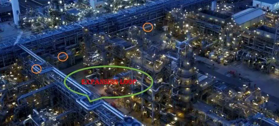
Fig. 6: Example of Expansion Loops in a Process Plant
What factors should be considered when designing an expansion loop?
When designing a thermal expansion loop, the factors that must be taken into consideration are:
Pipe Material
Temperature Differential (Install temperature to maximum and minimum design temperature)
Pipe Diameter: With an increase in pipe diameter, it becomes more rigid which may call for more flexibility and thus increase in expansion leg length.
Piping Layout: The layout of the piping system, including the placement of bends, elbows, and supports, affects how the thermal expansion is distributed. In a straight pipe run, thermal expansion will cause the pipe to elongate in the direction of the run. However, introducing bends and loops into the layout provides flexibility, allowing the pipe to expand and contract without imposing excessive stress.
Loop Dimensions: The size of the expansion loop is determined based on the amount of thermal expansion expected and the allowable stress on the pipe.
The required range of movement shall be considered.
What are the alternatives to expansion loops in piping and pipeline systems?
In a piping system, expansion loops can be avoided by providing suitable offsets. In critical systems where space is limited and offsets are not sufficient, expansion joints, bellows, or compensators are used as alternatives to piping expansion loops. In large-size pipeline systems, the zig-zag pipeline route is followed to avoid pipeline expansion loops to optimize space requirements by pipeline loops.
What are the Advantages of Piping Expansion Loops?
The main advantages of expansion loops are that they are:
Cost-effective
Simple in design
Can be easily installed
Low Maintenance.
What are the Disadvantages of Expansion Loops in a Piping System?
Expansion loops need more space requirements for their installation and to work properly. So, sometimes where there is a space constraint, expansion loops may not be feasible.
Video Tutorial on Piping Expansion Loop
For further doubts kindly refer to the following video tutorial
ASME B31.3 is the bible of process piping engineering and every piping engineer should frequently use this code for his knowledge enhancement. But to study a code similar to B31.3 is time-consuming and also difficult because the contents are not at all interesting. Also every now and then it will say to refer to some other point of the code which will irritate you. But still, every piping engineer should learn a few basic points from it. The following literature will try to point out 11 basic and useful points from the code of which every piping engineer must be aware of.
1. What is the scope of ASME B31.3? What does it cover and what does not?
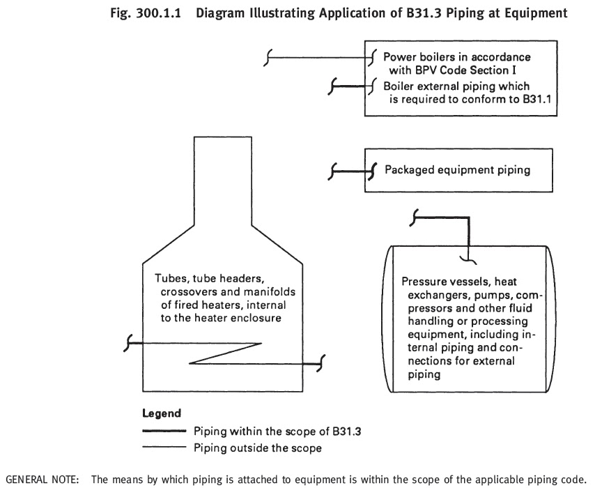
Ans: The Process Piping Code, ASME B31.3 is usually applicable for the piping systems in petroleum refineries; chemical, petrochemical, pharmaceutical, paper, textile, ore processing, onshore and offshore petroleum and natural gas production facilities; semiconductor, cryogenic plants; food and beverage processing facilities; and related processing plants and terminals. ASME B31.3 provides design, fabrication, erection, test, inspection, assembly, and material requirements for piping systems that carry the following fluids:
Packaged equipment piping design is also covered by the B31.3 code.
The process piping code ASME B31.3 typically does not cover the following:
The piping systems designed for internal gage pressures at or above zero but less than 105 kPa (15 psi), provided the fluid handled is non-flammable, non-toxic, and not damaging to human tissues as defined in 300.2, and its design temperature is from −29°C (−20°F) through 186°C (366°F).
Power boiler and power system piping following ASME B31.1
Fired heater internal piping.
Pressure vessels, heat exchangers, pumps, compressors, and other fluid handling or processing equipment, including internal piping and connections for external piping.
Alternatively, refer to the below-attached figure ( Figure 300.1.1 from code ASME B31.3)
2. What are the disturbing parameters against which the piping system must be designed?
Ans: The piping system must stand strong (should not fail) against the following major effects:
Design Pressure and Temperature: Each component thickness must be sufficient to withstand the most severe combination of temperature and pressure.
Ambient effects like pressure reduction due to cooling, fluid expansion effect, the possibility of moisture condensation, and build-up of ice due to atmospheric icing, low ambient temperature, etc.
Dynamic effects like impact force due to external or internal unexpected conditions, Wind force, Earthquake force, Vibration, discharge (Relief valve) reaction forces, cyclic effects, etc.
Component self-weight including insulation, rigid body weights along with the medium it transport.
Movement of pipe supports or connected equipments etc.
3. How to calculate the allowable stress for a carbon steel pipe?
Ans: The material allowable stress for any material other than bolting material, cast iron, and malleable iron is the minimum of the following:
one-third of tensile strength at maximum temperature.
two-thirds of yield strength at maximum temperature.
for austenitic stainless steels and nickel alloys having similar stress-strain behavior, the lower of two-thirds of yield strength, and 90% of yield strength at temperature.
100% of the average stress for a creep rate of 0.01% per 1000 h
67% of the average stress for rupture at the end of 100000 h for temperatures up to and including 815°C.
For temperatures higher than 815°C (1,500°F), (100 × Favg)% times the average stress for rupture at the end of 100000 h. Favg is determined from the slope, n, of the log time-to-rupture versus log stress plot at 100 000 h such that log Favg = 1/n. Favg shall not exceed 0.67.
80% of the minimum stress for rupture at the end of 100000 h
for structural grade materials, the basic allowable stress shall be 0.92 times the lowest value determined (1) through (7) above.
4. What is allowable for Sustained, Occasional, and Expansion Stress as per ASME B 31.3?
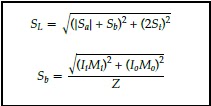
Ans: Calculated sustained stress (SL)< Sh (Basic allowable stress at maximum temperature) Calculated occasional stress including sustained stress< 1.33 Sh Calculated expansion stress< SA = f [ 1.25( Sc + Sh) − SL] Here f =stress range factor, Sc =basic allowable stress at minimum metal temperature and SL=calculated sustained stress. The sustained stress (SL) is calculated using the following code formulas:
Here,
Ii=sustained in-plane moment index. In the absence of more applicable data, Ii is taken as the greater of 0.75ii or 1.00.
Io=sustained out-plane moment index. In the absence of more applicable data, Io is taken as the greater of 0.75io or 1.00.
Mi=in-plane moment due to sustained loads, e.g., pressure and weight
Mo=out-plane moment due to sustained loads, e.g., pressure and weight
Z=sustained section modulus
It=sustained torsional moment index. In the absence of more applicable data, It is taken as 1.00.
Mt=torsional moment due to sustained loads, e.g., pressure and weight
Ap=cross-sectional area of the pipe, considering nominal pipe dimensions less allowances;
Fa=longitudinal force due to sustained loads, e.g., pressure and weight
Ia=sustained longitudinal force index. In the absence of more applicable data, Ia is taken as 1.00.
5. What are the steps for calculating the pipe thickness for a 10-inch carbon steel (A 106-Grade B) pipe carrying a fluid with a design pressure of 15 bar and a design temperature of 250 degrees centigrade?
D=Outside diameter of the pipe, obtain the diameter from pipe manufacturer standard.
S=stress value at design temperature from code Table A-1
E=quality factor from code Table A-1A or A-1B
W=weld joint strength reduction factor from code
Y=coefficient from code Table 304.1.1 Using the above formula calculates the pressure design thickness, t.
Now add the sum of the mechanical allowances (thread or groove depth) plus corrosion and erosion allowances if any with t to get the minimum required thickness, tm.
Next, add the mill tolerance with this value to get the calculated pipe thickness. For seamless pipe, the mill tolerance is 12.5% under tolerance. So calculated pipe thickness will be tm/(1-0.125)=tm/0.875.
Now accept the available pipe thickness (based on the next nearest higher pipe schedule) just higher than the calculated value from manufacturer standard thickness tables.
6. How many types of fluid services are available for process piping?
Ans: In the process piping industry following fluid services are available..
Category D Fluid Service: nonflammable, nontoxic, and not damaging to human tissues, the design pressure does not exceed 150 psig (1035kPa), the design temperature is from -20 degree F to 366 degrees F.
highly toxic fluid such that a single exposure to a very small quantity of the fluid, caused by leakage, can produce serious irreversible harm to persons on breathing or bodily contact, even when prompt restorative measures are taken.
after consideration of piping design, experience, service conditions, and location, the owner determines that the requirements for Normal Fluid Service do not sufficiently provide the leak tightness required to protect personnel from exposure.
Elevated Temperature Fluid service: a fluid service in which the piping metal temperature is sustained equally to or greater than Tcr (Tcr=temperature 25°C (50°F) below the temperature identifying the start of time-dependent properties).
Normal Fluid Service: a fluid service pertaining to most piping covered by this Code, i.e., not subject to the rules for Category D, Category M, Elevated Temperature, High Pressure, or High Purity Fluid Service.
High-Pressure Fluid Service: a fluid service for which the owner specifies the use of Chapter IX for piping design and construction.
High Purity Fluid Service: a fluid service that requires alternative methods of fabrication, inspection, examination, and testing not covered elsewhere in the Code, with the intent to produce a controlled level of cleanness. The term thus applies to pipe systems defined for other purposes as high purity, ultra-high purity, hygienic, or aseptic.
7. What do you mean by the term SIF?
Ans: The stress intensification factor or SIF is an intensifier of bending or torsional stress local to a piping component such as tees, and elbows, and has a value great than or equal to 1.0. Its value depends on component geometry. ASME B31.3 Appendix D, up to edition 2018 used to provide provides formulas to calculate the SIF values which are reproduced in the following figure. However, From ASME B31.3 Edition 2020 onwards Appendix D is deleted from the code and the code now suggests using ASME B31J or FEA calculations to find the values of Stress intensification factors.
Appendix D of B 31.3
8. When do you feel that a piping system is not required formal stress analysis?
Ans: Formal pipe stress analysis will not be required if any of the following 3 mentioned criteria are satisfied:
if the system duplicates or replaces without significant change, a system operating with a successful service record (operating successfully for more than 10 years without major failure).
if the system can readily be judged adequate by comparison with previously analyzed systems.
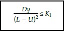
if the system is of uniform size, has no more than two points of fixation, no intermediate restraints, and falls within the limitations of the empirical equation mentioned below:
Here, D = outside diameter of the pipe, mm (in.) Ea = reference modulus of elasticity at 21°C (70°F), MPa (ksi) K1 = 208 000 SA/Ea, (mm/m)2 = 30 SA/Ea, (in./ft)2 L = developed length of piping between anchors,m (ft) SA = allowable displacement stress range U = anchor distance, straight line between anchors,m (ft) y = resultant of total displacement strains, mm (in.), to be absorbed by the piping system
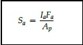
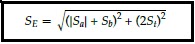
9. How will you calculate the displacement (Expansion) stress range for a piping system?
Ans: Expansion stress range (SE) for a complex piping system is normally calculated using software like Caesar II, Start-Prof, Rohr-II, or AutoPIPE. However, the same can be calculated using the following code equations:
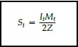
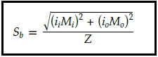
here Ap = cross-sectional area of pipe Fa = range of axial forces due to displacement strains between any two conditions being evaluated ia = axial stress intensification factor. In the absence of more applicable data, ia=1.0 for elbows, pipe bends, and miter bends (single, closely spaced, and widely spaced), and ia =io it = torsional stress intensification factor. Mt = torsional moment range between any two conditions being evaluated. Sa = axial stress range due to displacement strains= (ia X Fa )/Ap Sb = resultant bending stress range due to displacement strains. St = torsional stress range= (it X Mt )/2Z Z = section modulus of pipe ii = in-plane stress intensification factor io = out-plane stress intensification factor Mi = in-plane bending moment Mo = out-plane bending moment
10. What do you mean by the term “Cold Spring”?
Ans: Cold spring is the intentional initial deformation applied to a piping system during assembly to produce the desired initial displacement and stress. Cold Spring is beneficial in that it serves to balance the magnitude of stress under initial and extreme displacement conditions.
When cold spring is properly applied there is less likelihood of overstraining during initial operation; hence, it is recommended especially for piping materials of limited ductility. There is also less deviation from as installed dimensions during initial operation so that hangers will not be displaced as far from their original settings.
However, nowadays most EPC organizations do not prefer the use of the Cold Spring while analyzing any system.
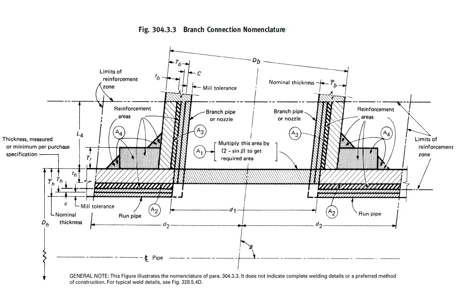
11. How to decide whether Reinforcement is required for a piping branch connection or not?
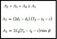
Ans: When a branch connection is made in any parent pipe the pipe connection is weakened by the opening that is made in it. So it is required that the wall thickness after the opening must be sufficiently in excess of the required thickness to sustain the pressure. This requirement is checked by calculating the required reinforcement area (A1) and available reinforcement area (A2+A3+A4) and if the available area is more than the required area then no reinforcement is required. Otherwise, additional reinforcement needs to be added. The equations for calculating the required and available areas are listed below for your information from the code. Please refer to the code for the notations used:
Few more piping stress interview questions with answers for you..
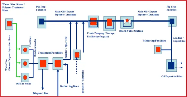
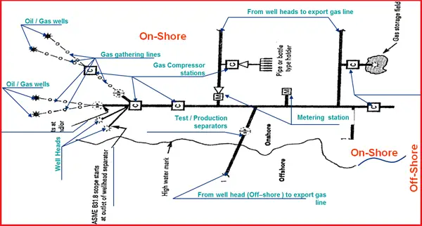
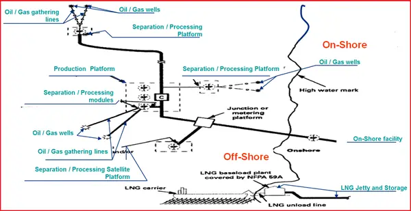
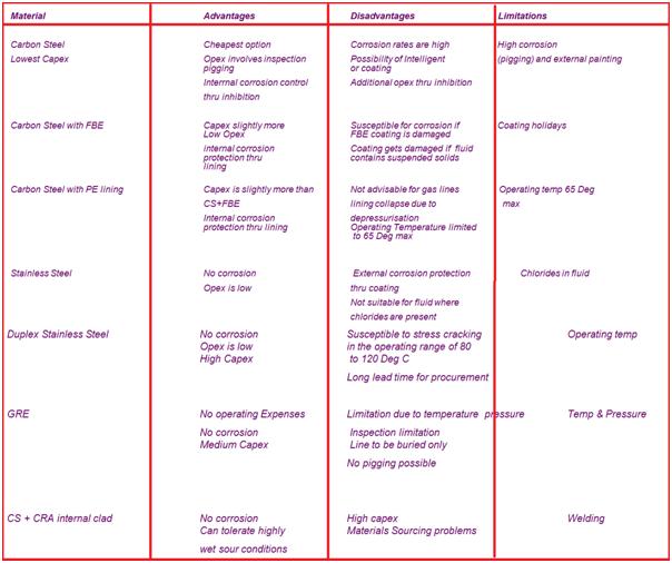
In the pipeline industry, various names are provided for the lines depending on the function and location of the pipelines. They are
Injection lines: Pipelines injecting water/steam/polymer/gas into the wells to improve the lift.
Flow lines: Pipelines from the wellhead to the nearest processing facility.
Trunk lines / Inter field lines: Pipelines between two processing facilities or from pig trap to pig trap or from block valve station to block valve station.
Export lines / Loading lines: From the processing facility to the loading or export point.
Transfer lines / Spur lines: Branch line exiting into trunk line or export line.
Gathering lines: One or more segments of pipelines forming networks and connected from the wells to processing facilities.
Disposal lines: Pipeline which disposes of normally produced water into disposal wells (shallow/deep).
Subsea pipelines: Pipelines connecting the offshore production platforms to onshore processing facilities.
Corrosion inhibitor: Basically meant for CS pipelines, forms a layer of film on the surface and protects the core pipe from corrosion attack. Batch injection or continuous
Scale Inhibitor: Prevents scale formation in the pipelines by dissolving scale-forming salts
Wax inhibitor: Dissolves the wax within the crude
Oxygen Scavenger: Reacts and removes oxygen in the fluid
Biocide: Destroys the bacteria, algae, and fungi in the process fluid.
Coagulant / Antifoam: Normally mixed in the separators to improve mixing and reducing the foam
Demulsifier: Prevents emulsion in the multiphase system
Dehydration agents: Removes moisture in the gas normally Glycol injection
Odorant: Added to the fluid to add smell and detect the leakage
Online Video Courses related to Pipeline Engineering
If you wish to explore more about pipeline engineering, you can opt for the following video courses