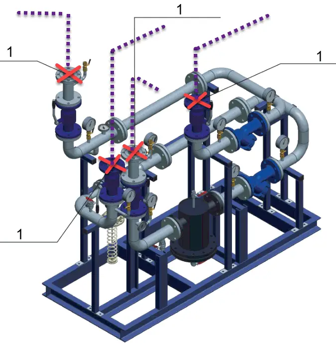
The idea of modular design is as follows: The complex piping system is divided into several modules that are mounted on a frame structure. Modules can be transported to the site and joined to each other into the entire piping system. One of the modules is shown in the picture below. At the points, “1” external piping or other module piping is connected.
Stress analysis of separate modules for temperature expansion and other loads acting on a whole system is impossible. Only the whole system can be analyzed. Exception: when anchors are added at all connection points between modules. But in this case design for temperature expansion will become extremely hard.
Sample Module
The practical solution to this problem is the following:
Option 1. Module manufacturer performs its stress analysis using of several, the most unfavorable variants of external piping design. Stress analysis should be successful for all variants. After that manufacturer passes the START-PROF module piping model to the customer. The customer adds the module model to own the piping model and performs an analysis of the whole system.
Option 2. The customer adds anchors or hinged anchors at the points, where his piping model is connected to the module. Performs stress analysis and optimize the design. After that, he passes the START-PROF piping model to the module manufacturer, who joins this model to the module piping model and preforms whole system stress analysis.
Option 1 & 2 can be simplified if you use the overlapping models when one part is included 100% and the second part included just partially.
There’s also Option 3. Too complex and hard. Module manufacturer offers 6 stiffnesses (Kx, Ky, Kz, KRx, KRy, KRz) for each connection point and temperature expansions (point movements). Also, the stiffness matrix 6×6 can be offered. The customer adds these stiffnesses and add support movements. But after analysis, he must pass new movements of connection points back to the manufacturer.
Also, piping systems usually are nonlinear. Some restraints may switch off, friction behavior may be different, therefore the manufacturer should perform new analysis and generate new stiffnesses and new movements. The design process will become iterative. If the piping system has several operation modes with various temperatures, this work becomes almost impossible. Much more easy to offer the whole piping model to counterpart. This option can only be used if the manufacturer wants to keep the design secret, but doesn’t want to use Option 2 for some reason.
Transportation Stage
The transportation stage should be calculated for both options described above. The system should have transportation configuration (locked springs, added temporary supports, detached flanges, etc.) and analyzed for inertial loads and vehicle body deformations during transportation. Added ice, show, wind, impact, and other possible loads.
Piping Elbows are very important pipe fitting which is used very frequently for changing direction in the piping, pipeline, and plumbing systems. They are essential pieces of fittings for routing pipes around obstacles or for creating a more efficient and organized pipe layout. Even though the terms “piping bends” and “piping elbows” are often used synonymously, they are not the same. In this article, we will discuss about:
Definition of Pipe Elbow
Types of Pipe Elbows
Features of Piping Elbow
Calculating Pipe Elbow Angle
Significance of Elbow Radius
Pipe Elbow Minimum Thickness Requirement
Piping Elbow End Connections
Pipe Elbow Material Specification
And many more…
What is a Piping Elbow?
A Pipe Elbow or Piping Elbow is a specific, standard, engineered bend pre-fabricated as a spool piece (based on ASME B16.9) and designed to either be screwed, flanged, or welded to the piping it is associated with. It is a type of pipe fittings. Pipe elbows are usually manufactured to provide a 45-degree or 90-degree direction change from the main pipe direction. There can also be custom-designed piping elbows, although most are categorized as either “short radius” or long radius”.
Types of Piping Elbows
Depending on various piping parameters, pipe elbows can be classified as follows:
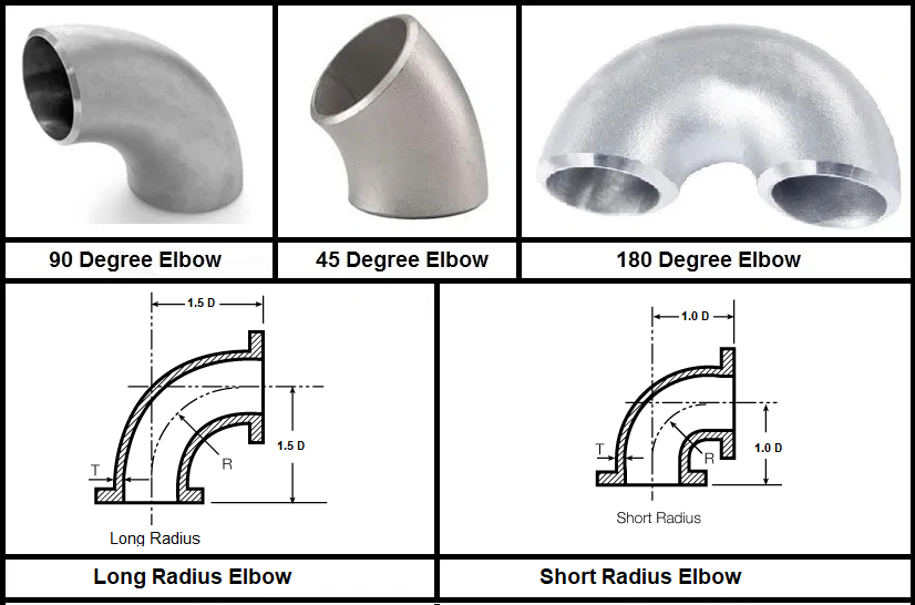
Piping elbow types based on direction angle
45-degree elbow
90-degree elbow
180-degree elbow
45-Degree Pipe Elbow:
A 45-degree elbow creates a 45-degree change in direction, providing a slightly less sharp turn than a 90-degree elbow. These types of pipe elbows are preferred when there is space limitation for pipe routing or there is a requirement for a more gradual change in direction to result in less turbulence and pressure drop.
90-Degree Elbow:
This type of elbow creates a 90-degree change in direction, either turning the flow of fluid from horizontal to vertical or vice versa. The majority of piping elbows used in piping or plumbing systems are 90-degree elbows.
180-Degree Elbow:
A 180-degree elbow, also known as a U-bend or return bend, is used to change the direction of a pipe/pipeline by a complete reversal of direction, resulting in a 180-degree turn. Unlike 45-degree and 90-degree elbows, which provide gradual changes in direction, a 180-degree elbow completely flips the direction of flow back on itself. In situations where a complete u-turn of pipe routing is required 180-degree pipe elbows can be used to eliminate the requirement of two 90-degree elbows. In general, they are frequently used in piping/plumbing systems.
Refer to Fig. 1 shows various types of piping elbows
Fig. 1: Types of piping elbows
Types of piping elbows depending on bend radius
Long radius elbow
Short radius elbow
Long-radius and short-radius pipe elbows differ in terms of their curvature and the radius of the bend.
Long Radius Elbow:
A long-radius pipe elbow has a larger radius of curvature compared to short-radius elbows. The radius of a long-radius elbow is typically 1.5 times the nominal pipe diameter. They provide a more gradual change in direction, resulting in less resistance to fluid flow and reduced pressure drop. Long-radius elbows are often preferred in situations where minimizing flow resistance and maintaining a smooth flow path are important. They are the most widely used piping elbows and are found in applications with higher flow rates, such as in large industrial piping systems or when handling viscous fluids. These elbows are also suitable for applications where space is not a major constraint, as they require more room to accommodate their larger curvature.
Short Radius Elbow:
Short-radius elbows, on the other hand, have a smaller radius of curvature, typically equal to 1.0 times the nominal pipe diameter. They create a sharper change in direction, which can lead to higher resistance to fluid flow and increased pressure drop compared to long-radius elbows. Short-radius elbows are often used in situations where space is limited, and a tighter turn is required to navigate around obstacles or fit within confined spaces. They are usually not preferred by pipe layout engineers or pipe designers but are used when there is limited room for pipe layout routing adjustments. These elbows are commonly found in applications like shipbuilding, process equipment, and tight mechanical rooms.
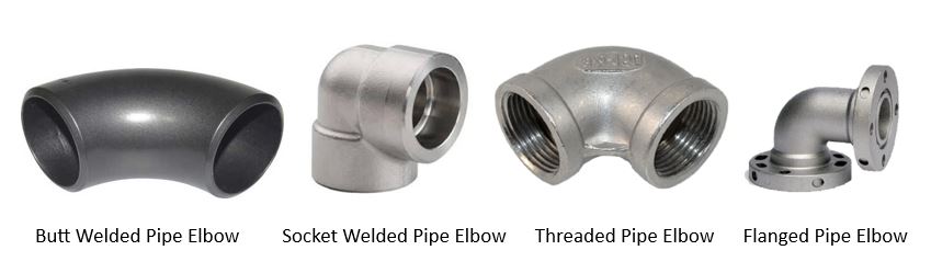
Piping elbow types considering pipe end connections
Butt welded piping elbow
Socket welded piping elbow
Threaded piping elbow
Flanged elbow
Butt Welded Piping Elbow:
A butt-welded piping elbow is a type of pipe elbow that is joined to the pipeline through a butt-welding process. Butt welding involves welding the elbow directly to the pipe by aligning the ends of the pipe and the elbow and then fusing them together using heat and pressure. Butt welded elbows are known for their strength and integrity as the weld provides a continuous, leak-resistant joint. They are commonly used in high-pressure and high-temperature piping systems, especially in industrial piping applications. Refer to Fig. 2 below
Fig. 2: Types of Pipe Elbows as per End Connection
Socket Welded Piping Elbow:
A socket-welded piping elbow is a type of pipe elbow designed to be joined to the pipeline using socket weld connections. In this process, the pipe is inserted into the socket of the elbow, and then fillet welds are applied to secure the joint. Socket welded elbows are suitable for smaller-diameter pipes and are often used in applications where a strong and reliable connection is needed but without the need for complex welding procedures. They are commonly used in low- to medium-pressure piping systems.
Threaded Piping Elbow:
A threaded piping elbow is a pipe elbow with female threads on both ends, allowing it to be screwed onto threaded pipes or fittings with male threads. The connection is made by threading the elbow onto the pipe threads. Threaded elbows are convenient for assembly and disassembly, making them suitable for applications where frequent maintenance or changes to the piping system may be required. They are commonly used in plumbing and lower-pressure industrial piping systems.
Flanged Elbow:
A flanged elbow is a type of pipe elbow with flanges on both ends. These flanges have holes for bolting the elbow to the matching flanges on pipes or equipment. The joint is sealed using gaskets between the flange faces. Flanged elbows are often used in applications where easy assembly and disassembly are necessary, and they are particularly prevalent in large-diameter pipes and systems with higher pressure and temperature requirements. The flange connection allows for a secure and leak-proof joint.
Other Pipe Elbow Types
Reducing Elbow
A reducing elbow is a type of pipe elbow used in piping systems to change the direction of flow while also reducing the pipe diameter or size in the process. It combines the functions of a standard elbow, which redirects the flow, with that of a reducing coupling or adapter, which reduces the pipe size. Reducing elbows are designed to accommodate situations where two pipes of different sizes need to be connected while maintaining the required change in direction. Reducing pipe elbows are in various end connection types, including butt weld, socket weld, threaded, or flanged, depending on the specific requirements of the piping system.
Features of Piping Elbow
Whenever the term piping elbow is used, it must also carry the qualifiers of type (45 or 90 degrees) and radius (short or long) – besides the nominal size.
Elbows can change direction to any angle as per requirement. An elbow angle can be defined as the angle by which the flow direction deviates from its original flowing direction (See Fig. 3 below). Even though An elbow angle can be anything greater than 0 but less or equal to 90° But still a change in direction greater than 90° at a single point is not desirable. Normally, a 45° and a 90° elbow combinedly are used while making piping layouts for such situations.
Fig. 3: A Typical Piping Elbow with Elbow Angle (phi)
Calculating Elbow Angle
Elbow angle can be easily calculated using a simple geometrical technique of mathematics. Let’s give an example to you.
Refer to Fig. 4. Pipe direction changes at point A with the help of an elbow and again the direction changes at point G using another elbow.
Fig. 4: Example figure for elbow angle calculation
In order to find out the elbow angle at A, it is necessary to consider a plane that contains the arms of the elbow. If there had been no change in direction at point A, the pipe would have moved along line AD but the pipe is moving along line AG. Plane AFGD contains lines AD and AG and the elbow angle (phi) is marked which denotes the angle by which the flow is deviating from its original direction. Considering right angle triangle AGD, tan(phi) = √( x2 + z2)/y Similarly elbow angle at G is given by: tan (phi1)=√ (y2 +z2)/x
Elbow Radius | Bend Radius
Elbows or bends are available in various radii for a smooth change in direction which is expressed in terms of pipe nominal size expressed in inches. Elbows or bends are available in three radii,
a. Long radius elbows (Radius = 1.5D): used most frequently where there is a need to keep the frictional fluid pressure loss down to a minimum, there is ample space and volume to allow for a wider turn and generate less pressure drop.
b. Long radius elbows (Radius > 1.5D): Used sometimes for specific applications for transporting high viscous fluids like slurry, low polymer, etc. For radius, more than 1.5D pipe bends are usually used and these can be made to any radius. However, 3D & 5D pipe bends are the most commonly used. In the pipeline industry, a piping bend of up to 60D is quite common.
c. Short radius elbows (Radius = 1.0D): to be used only in locations where space does not permit the use of long radius elbows and there is a need to reduce the cost of elbows. In jacketed piping, the short radius elbow is used for the core pipe.
Here, D is the nominal pipe size in inches.
There are three major parameters that dictate the radius selection for the elbow. Space availability, cost, and pressure drop Pipe bends are preferred where pressure drop is of major consideration. The use of short-radius elbows should be avoided as far as possible due to abrupt changes in a direction causing the high-pressure drop.
Pipe Elbow Minimum Thickness Requirement
Whether a pipe elbow or bend is used the minimum thickness requirement from the code must be met. Code ASME B31.3 provides an equation for calculating the minimum thickness required (t) in finished form for a given internal design pressure (P) as shown below:
Fig. 5: Code Equation for Minimum Elbow Thickness Calculation
Here,
R1 = bend radius of welding elbow or pipe bend
D = outside diameter of the pipe
W = weld joint strength reduction factor
Y = coefficient from Code Table 304.1.1
S = stress value for material from Table A-1 at the maximum temperature
E = quality factor from Table A-1A or A-1B Add any corrosion, erosion, or mechanical allowances with this calculated value to get the thickness required.
Pipe Elbow Material Specifications
The material specifications for pipe elbows can vary widely depending on the specific requirements of the piping system, the type of fluid being transported, and the environmental conditions. Different materials offer varying levels of corrosion resistance, strength, and temperature tolerance. Below are some common ASTM material specifications used for pipe elbows:
Carbon Steel Piping Elbows:
ASTM A234/A234M Standard Specification for Piping Fittings of Wrought Carbon Steel and Alloy Steel for Moderate and High-Temperature Service.
ASTM A420/A420M Standard Specification for Piping Fittings of Wrought Carbon Steel and Alloy Steel for Low-Temperature Service.
Stainless Steel Pipe Elbows:
ASTM A403/A403M Standard Specification for Wrought Austenitic Stainless Steel Piping Fittings.
ASTM A815/A815M Standard Specification for Wrought Ferritic, Ferritic/Austenitic, and Martensitic Stainless Steel Piping Fittings.
Copper and Copper Alloys Pipe Elbows:
ASTM B16/B16M Standard Specification for Free-Cutting Brass Rod, Bar, and Shapes for Use in Screw Machines.
ASTM B75/B75M Standard Specification for Seamless Copper Tube.
PVC (Polyvinyl Chloride) Pipe Elbows:
ASTM D2466 Standard Specification for Poly(Vinyl Chloride) (PVC) Plastic Pipe Fittings, Schedule 40.
ASTM D2467 Standard Specification for Poly(Vinyl Chloride) (PVC) Plastic Pipe Fittings, Schedule 80.
ASTM D2846 Standard Specification for Chlorinated Poly(Vinyl Chloride) (CPVC) Plastic Hot-and-Cold-Water Distribution Systems.
Ductile Iron Piping Elbows:
ASTM A536 Standard Specification for Ductile Iron Castings.
ISO 2531 Ductile iron pipes, fittings, accessories, and their joints for water applications.
Brass Elbows:
ASTM B62 Standard Specification for Composition Bronze or Ounce Metal Castings.
ASTM B124/B124M Standard Specification for Copper and Copper Alloy Forging Rod, Bar, and Shapes.
Aluminum Pipe Elbows:
ASTM B361 Standard Specification for Factory-Made Wrought Aluminum and Aluminum-Alloy Welding Fittings.
Titanium Elbows:
ASTM B363 Standard Specification for Seamless and Welded Unalloyed Titanium and Titanium Alloy Welding Fittings.
Nickel Alloys:
ASTM B366 Standard Specification for Factory-Made Wrought Nickel and Nickel Alloy Fittings.
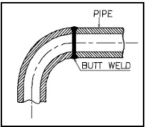
Butt-Welded Pipe Elbows
Butt-welded piping elbows are the most widely used pipe connections for high-temperature and pressure lines. They are normally used for pipe sizes with a size of NPS 2 or more. The pipe is connected to butt welded elbow as shown in Fig. 6 by having a butt-welding joint.
Butt-welded fittings are supplied with bevel ends suitable for welding to the pipe. It is important to indicate the connected pipe thickness /schedule while ordering. All edge preparations for butt welding should conform to ASME B16.25.
Dimensions of butt welded elbows are as per ASME B16.9. This standard is applicable for carbon steel & alloy steel butt weld fittings of NPS 1/2” through 48”.
Fig. 6: A Typical Butt-Welded Elbow
Dimensions of stainless steel butt welded fittings are as per MSS-SP-43. Physical dimensions for fittings are identical under ASME B16.9 and MSS-SP-43. It is implied that the scope of ASME B16.9 deals primarily with the wall thicknesses which are common to carbon and low alloy steel piping, whereas MSS-SP-43 deals specifically with schedule 5S & 10S in stainless steel piping.
Dimensions for short radius elbows are as per ASME B16.28 in the case of carbon steel & low alloy steel and MSS-SP-59 for stainless steel.
Butt-welded fittings are usually used for sizes 2” & above. However, for smaller sizes up to 1-1/2” on critical lines where the use of socket welded joints is prohibited, pipe bends are normally used. These bends are usually of a 5D radius and made at the site by cold bending of the pipe.
Alternatively, butt welded elbows can be used in lieu of pipe bends but usually smaller dia lines are field routed and it is not possible to have the requirement known at the initial stage of the project for procurement purposes. So pipe bends are preferred. However, pipe bends do occupy more space and particularly in pharmaceutical plants where a major portion of piping is of small diameter and the layout is congested, butt welded elbows are preferred.
Butt-welded joints can be radiographed and hence preferred for all critical services.
ASME B31.3 allows the application of miter bends subject to meeting its pressure requirements.
Material standards as applicable to butt welded fittings are as follows:
ASTM A234
This specification covers wrought carbon steel & alloy steel fittings of seamless and welded construction. Unless seamless or welded construction is specified in the order, either may be furnished at the option of the supplier. All welded construction fittings as per this standard are supplied with 100% radiography. Under ASTM A234, several grades are available depending on chemical composition. Selection would depend upon the pipe material connected to these fittings. Some of the grades available under this specification and corresponding connected pipe material specifications are listed below:
ASTM A403
This specification covers two general classes, WP & CR, of wrought austenitic stainless steel fittings of seamless and welded construction. Class WP fittings are manufactured to the requirements of ASME B16.9 & ASME B16.28 and are subdivided into three subclasses as follows:
WP-S-Manufactured from a seamless product by a seamless method of manufacture.
WP – W These fittings contain welds and all welds made by the fitting manufacturer including starting pipe weld if the pipe was welded with the addition of filler material are radiographed. However, no radiography is done for the starting pipe weld if the pipe was welded without the addition of filler material.
WP-WX These fittings contain welds and all welds whether made by the fitting manufacturer or by the starting material manufacturer are radiographed.
Class CR fittings are manufactured to the requirements of MSS-SP-43 and do not require non-destructive examination. Under ASTM A403 several grades are available depending on chemical composition. Selection would depend upon the pipe material connected to these fittings. Some of the grades available under this specification and corresponding connected pipe material specifications are listed below:
ASTM A420
This specification covers wrought carbon steel and alloy steel fittings of seamless & welded construction intended for use at low temperatures. It covers four grades WPL6, WPL9, WPL3 & WPL8 depending upon chemical composition. Fittings WPL6 are impact tested at temp – 50° C, WPL9 at -75° C, WPL3 at -100° C and WPL8 at -195° C temperature.
The allowable pressure ratings for fittings may be calculated for straight seamless pipe in accordance with the rules established in the applicable section of ASME B31.3.
The pipe wall thickness and material type shall be that with which the fittings have been ordered to be used, their identity on the fittings is in lieu of pressure rating markings.
Piping Elbow vs. Piping Bend
A PIPING BEND is simply a generic term in piping for an “offset” – a change in the direction of the piping. It signifies that there is a “bend” i.e., a change in direction of the piping (usually for some specific reason) – but it lacks a specific, engineering definition as to direction and degree. Bends are usually made by using a bending machine (hot bending and cold bending) on-site and suited for a specific need. The use of bends is economical as it reduces the number of expensive pipe fittings. The major differences between a pipe elbow and a pipe bend are provided in Table 1 below:
Pipe Bend
Pipe Elbow
A pipe bend is a generic term for a curved section of a pipe used to change the direction of the pipeline.
A pipe elbow is a specific type of pipe fitting designed to change the direction of flow at a particular angle, typically 90 degrees or 45 degrees.
Pipe bends can come in various angles, including 90 degrees, 45 degrees, or other custom angles.
Pipe elbows are primarily available in two common angles: 90 degrees and 45 degrees, although other angles are possible.
Pipe bends may have a varying radius of curvature depending on the design and application.
Pipe elbows can be categorized as either long radius or short radius, each with its own specific radius of curvature.
Pipe bends can be fabricated by bending a straight section of pipe to the desired angle using heat and mechanical force or by welding together straight pipe segments.
Pipe elbows are manufactured as dedicated fittings, and their shape is consistent with their specified angle and radius of curvature.
Pipe bends are often used in custom or field-fabricated applications where specific bending requirements exist, or when standard elbows are not readily available.
Pipe elbows are standard fittings commonly used in piping systems to achieve predetermined angles for changing direction.
The curvature and angle of a pipe bend may vary depending on the fabrication method and skill of the welder, potentially leading to inconsistencies.
Pipe elbows are manufactured with precise angles and radii, ensuring consistency and reliability in pipe routing.
Pipe bends can be compatible with various materials and sizes, depending on how they are fabricated.
Pipe elbows are designed to be compatible with specific pipe sizes and materials, conforming to industry standards.
Pipe bends are not standardized fittings and may require custom fabrication for each application.
Pipe elbows are standardized pipe fittings available in various materials and sizes, conforming to industry standards.
Pipe bends are used in specialized or custom situations where a standard elbow may not fit or when specific bending requirements exist.
Pipe elbows are used as standard fittings in most piping systems to facilitate changes in direction while maintaining flow efficiency.
Pipe bends may require custom fabrication for replacements, making maintenance more complex and time-consuming.
Pipe elbows are readily available as standard fittings, simplifying maintenance and replacement tasks.
Table 1: Differences between Pipe Elbows and Pipe Bends
In short “All pipe elbows are bends as they change direction but all pipe bends are not elbows as they are not pipe fittings”
Pipe elbows are used in a wide range of industries, including plumbing, HVAC (heating, ventilation, and air conditioning), oil and gas, chemical and petrochemical processing, shipbuilding, marine, food processing, power plants, and many more.
Plant layout design means efficiently placing equipment, piping, instrumentation, and other manufacturing supports and facilities with proper planning during the design stage to create the most effective plant layout. It is directly related to project costs as well. The most efficient plant layout has less overall project cost and the most utilization of all resources.
The main objective of efficient plant layout design is to design and construct the plant in an economic fashion that meets all the process requirements and client specifications while operating in a safe reliable manner. This article provides the basic considerations for the development of plant layout. For more details on any of the listed points, you can refer to any standard piping books.
Principles of Plant Layout
While developing plant layouts following 10 principles are kept in mind.
PRINCIPLES OF PLANT LAYOUT
Plant Layout Design rules for Site Selection
Location
Area Allocation
Transport Facilities
Manpower availability
Industrial Infrastructure
Community Infrastructure
Availability of Water
Availability of Power
Effluent Disposal
Availability of Industrial Gas
Site Size
Ecology
Pollution
What is Plot Plan & its requirement?
The plot plan is the master plan locating each unit/facility within the plot boundary for a process industry such as
Refinery
Chemical /Agro Chemical / Petro Chemical / Organic Chemical / Inorganic Chemical
Fertilizer
Pharmaceutical
Metallurgical
Power Generation
It is used to locate the unit/facility.
The following main aspects shall be considered during the development of the layout.
Process requirement
The economy of piping material and cables
Erection & Construction requirements
Safety requirements.
Operation and Maintenance requirements.
Grouping of similar equipment for the convenience of maintenance & safety wherever possible.
Data to be collected before starting the process of plant layout development
Data from the Civil Department
Plane table survey map.
Contour survey map.
Soil bearing capacity.
Nature of Soil
Rail/Road Access.
Data required from Electrical Team
Location of Electric Supply Point.
Supply voltage levels.
Fault Levels.
Voltage Levels required within the unit.
Proposed distribution scheme.
Non-Plant Facilities
Administrative Block
Canteen
Workshop
R&D, QC Lab, and Pilot Plant
GateHouse/Time office
Security Arrangements
Vehicle Parking
Medical Centre
Ware House
Covered Area
Open Area
Solid Warehouse
Liquid Warehouse
Steel / Scrap Yard
Fire Station
Weigh Bridge
Staff Colony
Meteorological Data
Minimum, Maximum, and Normal Temperature during the year
Rainfall
Intensity and Direction of the wind (wind rose)
Seismic zone
Wet and Dry Bulb temperatures
Relative humidity
Flood level
Process Data
Size/Capacity of the processing unit
Knowledge of the type of plant
The sequence of process flow
Hazardous nature of the plant
The Overall operating philosophy
Fully Automatic
Partially Automatic
Manual
Batch/Continuous
Raw material receipt and product dispatch philosophy
Storage Philosophy
Effluent plant capacity and discharge points, incineration requirements, etc.
Type of Hazard
No of flares
Data on Utilities
Source and/or supply point of raw water
Quality of Water available
Water Consumption for the process
The requirement of different types of utilities such as Steam, Air, Nitrogen, DM water, Firewater, Brine, etc.
Capacities and Grouping philosophy.
Statutory Requirements and process plant layout
State Industrial Development Corporation (SIDC)
Central / State Environmental Pollution Control Boards (PCBs)
Factory Inspectorate
State Electricity Boards (SEB)
Chief Controller of Explosives (CCOE)
Static and Mobile Pressure Vessel Rules (SMPV)
Tariff Advisory Committee (TAC)
National Fire Protection Association (NFPA)
Aviation Laws
Chief Inspector of Boilers (CIB)
Oil Industry Safety Directorate (OISD)
Food and Drug Administration (FDA)
Ministry of Environment and Forest (MoEF)
Expansion Philosophy during plant layout development
Within the unit
Additional Units
Near future expansion
Far future expansion
Considerations during plant layout
Normally Construction is permitted on a maximum of 50% of the plot area with a total built-up area equal to the area of the plot (i.e. F.S.I. = 1 (Depending upon the regulation governing the area and the type of industry))
The area reserved for tree plantation shall be 1/3 of the area occupied.
Water storage capacity – 24 hr. minimum.
Domestic water – 100 liters per person per day
Water requirement for Boiler – Steam rating x Working factor
Cooling tower – 11/4 % of capacity as drift and blowdown losses
Washing – 10-15 liters per day per sq. ft. of the floor area of the plant
Gardening – 5 liters per day per sq. ft. of garden area
Parking space – 10% of the plot area
Roads & Paving considerations in Plant Layout
Roads in the plant shall be planned for the effective movement of trucks, cranes & emergency vehicles, etc. Road width (Blacktop) shall be generally as follows unless specially requested.
Main plant road & roads connecting to Plant boundaries, roads for fire fighting access are 6 meters wide (Min)
Secondary roads 4 meters wide (Min)
The turning radius of the road shall be adequate for the mobile equipment & shall clear of any obstruction. The minimum turning radius is to be the same as the length of the vehicle.
The finish of the road i.e. graded or blacktop shall be decided in the beginning while developing a plot layout.
Paving should be provided around the equipment where spillage is likely to occur. For example Pumps or machinery, below furnaces or fired heaters, compressors, etc.
Also paving should be provided below the Air fin cooler those are located at grade.
Area handling acids, alkalis, or toxic material shall be paved and bunded. Proper surface treatment shall be provided for paving to meet the service requirements.
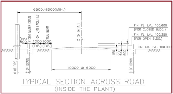
The below sketch (Fig. 1) shows the minimum distance required between the road and the facility. This distance shall be reviewed on a case-to-case basis for the project.
Fig. 1: Minimum distance required between the road and the facility
Elevations Requirement
Below data for the elevations should be generally followed.
Underside the base plate of Structural steel: Min150 mm. above HP of finished grade/paving.
Stair or ladder pads: Minimum 75 mm. above HP of finished grade/paving.
Top of Pedestal of Vessel & Tower: Min300 mm. above HP of finished grade/paving.
Top of Pump pedestal: Minimum 200 mm. above HP of finished grade/paving.
Insulation & Fire Proofing considerations in plant layout
Fireproofing requirements for pipe racks, vessel supports, and process structure should be considered as these reduce the clearances with access, pipework, instrument & electrical equipment.
Proper insulation thickness should be considered for pipework & equipment clearances.
Equipment Layout and locations
Pumps: Locate pumps close to the suction source considering NPSH requirements. Pumps & driver axis should be located perpendicular to the pipe rack or other equipment to minimize fire exposure in case of pump seal failure.
Gas compressor or Expanders: Gas compressors should be located downwind of the fired heaters, flare, or any open flame equipment. They may be grouped together for maintenance & operations (Common EOT / drop-down area, the single sunshade can be made)
Plant Air & Instrument air compressors: Plant air & instrument air is vital to the service of the plant. These units should be located near the control room & shall be kept in a safe area sufficiently away from the HAC of equipment.
Heat Exchangers:Heat exchangers are generally placed on grade unless otherwise due to process or technical reasons. (Platform for vertical heat exchangers, Tube bundle removal area, access to mobile crane or monorail with hoist shall be considered)
Air cooler: The air cooler is located in such a way as to allow access to mobile lifting equipment. Preferably air cooler is located in the main equipment row in accordance with process requirements.
Cooling Towers:Cooling towers shall be located away from the process equipment & downwind of the process equipment, substation, and main pipe rack.
Offsite Tanks:Storage tanks (Grouped and shall be surrounded by a dike wall, Primary/secondary roads for adequate firefighting accessibility, Lower elevations than the other occupancies and downwind flares, furnace heaters). Emergency shutdown valve, pumps, manifold & transfer piping shall be outside the dike area.
Considerations for Pipe ways / Pipe racks
Pipe ways or pipe racks should be overhead in-process main unit and at grade in off-site.
Width is determined based on present need + 10% at outset of the job + 15% for future requirements or as specified by the client.
The requirement of expansion bays, anchor bays & bracing shall be checked with the stress / structural engineer at the beginning of the pipe rack layout.
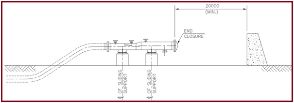
The area at the end closure of the Receiver shall be kept free to avoid any incident.
Provide a concrete wall a minimum of 20 meters away (Fig. 2) from the end closure if the area needs to be utilized for any equipment.
Fig. 2: Clearance at Pig Launcher
Personal protection Considerations
Eyewash and emergency showers shall be provided in an area where operators are subject to hazardous sprays or spills.
Breathing air stations in the facilities handling extremely toxic gases/fluids.
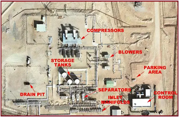
Fig. 3 shows a typical plant layout.
Fig. 3: Typical plant layout
What is a Hazard Classification?
Hazardous area classification is the risk locating plan for each unit/facility within the plot boundary for the process industry.
The Plot plan will be used by indicating the boundaries of the risk area.
HAC drawings are generally used by operators while issuing work permits.
HAC Standard
HAZARDOUS AREA: An area in which an explosive gas atmosphere is present, or maybe expected to be present, in quantities such as to require special precautions for the construction, installation, and use of apparatus.
NON-HAZARDOUS AREA: An area in which an explosive gas atmosphere is not expected to be present, in quantities such as to require special precautions for the construction, installation, and use of apparatus.
Process Requirements
Proper interconnection between equipment to achieve intended process parameters.
Normally equipment is arranged in the process fluid flow sequence. Requirement like gravity flow (Equipment Drain piping), Thermosyphon system should be considered, and Limitation of pressure & temperature (process parameters) to be considered
The requirement of upstream and downstream pipe lengths for instruments.
Equipment handling hazardous fluids like flares and direct-fired equipment containing open flame shall be located separately.
Similarly, equipment handling toxic material shall be located with restricted access or in accordance with local statutory regulations.
Economic Considerations
Equipment shall be located without affecting the process requirement for maximum economy of pipework & supporting steel with consistent standard clearances, construction, and maintenance & safety requirements.
Runs of exotic material & large bore piping shall be minimized.
Optimum utilization of the structure to be ensured.
Erection & Construction
Road access for the erection of pipe support/pipes and equipment.
The clear area for the crane to erect equipment on the location from the trucks.
The minimum one side of the pipe rack shall be kept clear.
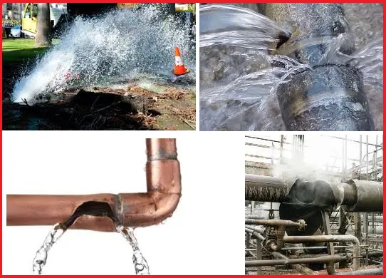
Water hammer, Pressure Surge, or hydraulic shock, is a term for the destructive pressure increase and accompanying shock wave that takes place in pipeline or piping systems when the flow rate of liquid changes suddenly. A large vapor pocket is formed because of this within the pipeline; and when this vapor pocket collapses, a highly powerful, bidirectional pressure wave propagates away from the origin at a very very high speed. In extreme situations, the magnitude of this shock wave can reach up to 100 times the closure velocity of the pocket. In the actual scenario, This huge force can force the pump shell to rupture.
What Can Cause Water Hammer?
Sudden flow restriction due to valve closure or pump trip, load shedding, etc. isthe most popular reason behind water hammer phenomena. If any of the above is the actual cause, the pump operators can easily reduce or even eliminate the possibility of water hammering by using proper valve closure procedures.
However, the pumping environment can also be one of the reasons for its creation. For example, In the phosphate industry pressure surge in pit pump applications are the most common. In such cases, during operation, the suction pipe can become blocked, but not during valve closure. While quick filling of long pipelines Surge can occur where the flowing fluid and the static fluid meet.
Destructive Impacts due to Water Hammer
Predicting Water Hammer
Since a water hammer or surge manifests as a shock wave, it is really very difficult to predict its point of origin or source until a rupture arises. Anyone or anything in close proximity to these pipelines is at high risk in the event of a water hammer and the resulting pipeline movement, so pump operators have to be extra cautious when there is any chance of a water hammer.
Water hammers may not be so destructive in all situations. In less severe cases, a banging or hammering noise is heard and it may also bend or move the pipe or its support.
Difference between Water Hammer and Cavitation
Sometimes, a water hammer or surge is confused with pump cavitation, but both are two different phenomena. However, cavitation can easily increase the potential risk of water hammer. In normal practice, cavitation itself is not always so destructive. The main difference between the two is that Cavitation involves the implosion of many small, localized vapor pockets whereas the water hammer involves the collapse of a single large vapor pocket. Cavitation damage builds up over time before causing a part to fail; conversely, a single instance of water hammer may cause catastrophic damage.
Extreme cavitation can occasionally result in a water hammer. For example, when cavitation is not severe enough to stop operation entirely but severe enough to impede pumping, a vapor pocket is expected to form in the pipeline. When pumping resumes, the pocket collapses, thereby causing a water hammer.
How to Stop Water Hammer
The main step towards reducing the water hammer possibility is by educating the pump and valve operators or plant operators.
As it is well-known that quick valve closing is the ultimate cause of water hammer generation, it is the responsibility of the valve operators to close the valves in the correct way as mentioned in the operating manuals.
For situations where the pump suction gets blocked, plant operators must stop the pumps following the same sequence of steps that they would use while a controlled shutdown is planned. In such cases, the vapor pocket will close at the minimum possible velocity this, in turn, will limit the magnitude of the shock wave to a minimum.
Operators should attempt to control the suction pipe movement and position it at the pipe entrance to keep it free from blocking. However, if there is a slump in the mining or dredging face, the pipe may still become blocked. Such risks can be carefully considered before moving the suction pipe entrance, as it may cause a water hammer.
So, by identifying and understanding the causes of surge or water hammer in pumps, and by following proper operating procedures, operating manuals, and vendor guidance notes, plant operators can prevent a disaster from happening due to water hammer. However, the pumping environment also plays an important role and situations may require expert help.
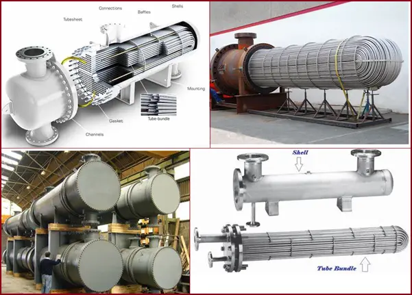
This article will highlight a few of the points that are required to be checked while reviewing the Shell & Tube Heat exchanger. The list is not exhaustive but provides a simple guideline for beginners.
Basic Checks for Shell & Tube Heat Exchanger
Check the Pressure Design Code to be applied and Applicable local regulations to be applied.
Check completeness and correctness of the information, dimension, impingement plate, gasket recommendation, the applicability of IBR, TEMA type and configuration, etc. are available on the datasheet.
Ensure the latest issue of the process data sheet is followed.
Check if any specific notes to be highlighted like anodic protection or sloping shell, any special service requirements like NACE/Sour service, etc. are applicable which puts restrictions on material requirements.
Ensure adequacy of shell Internal Diameter to accommodate all tubes with given pitch and orientation, the required number of tie rods, considering the provision of impingement plate, minimum U tube radius, and groove width, ligament as per TEMA recommendation is checked before starting design work.
Design codes including wind, seismic load, and any reference books with edition number and year of publication and amendments if any have been specified and used in the calculations.
Applicable standard specifications, Job specifications, and standards with their revision numbers.
Nozzle schedule indicating the size, rating, and nozzle neck thickness, projections and surface finish of gasket surface of nozzle flange (projection to suit insulation thickness and facing to suit gasket material), Nozzle location, Orientation, etc.
Provision of Instrument connection as per TEMA and Provision of vent or drain connection for testing
Support details (lugs, saddles) indicating size, numbers & PCD of foundation bolts. Foundation bolts are to be specified with their size and thread pitch in mm.
Typical applicable weld details of plates, Nozzles, and other attachments depending upon the material of construction, and the thickness of parts. (Special attention required. for cladding/lining)
Provision of standard attachments like Nameplate, Earthing boss,
Tube expansion requirements for strength welded tubes.
Adequacy and applicability of general notes
Ensure that the statement “In general the provisions of ASME / TEMA have to be followed in addition to the local company specification.”
On-site storage is required for more than 12 months prior to installation.
Surface preparation and painting, the surface finish of flange faces with respect to specified gaskets to be specifically checked
In the case of the stacked heat exchanger, a note stating that the final hydro-test shall be conducted in a stacked condition must be added.
Surface preparation and protection requirements
For stacked heat exchangers, the requirement of shim plates as required for adjustment shall be included.
Sliding support anchor bolts should be hand tightened and for high-temperature exchanger Teflon / graphite/Stainless steel sheet below sliding saddle to be indicated with the responsibility of its provision by the supplier.
Grooving requirements for shell side clad tube sheets.
In the case of the cryogenic exchanger, wooden saddles/Foam glass of adequate thickness below saddle plates are to be indicated.
TEMA minimum requirements for Shell & Tube Heat Exchanger
Check if the test ring is included for ‘U’ tubes kettle type & floating heat exchangers. The testing arrangement as required for other types has also been included in the supplier’s scope.
Check if lifting lugs, jack screws, and locating pins are provided.
In the case of ‘U’ tubes
The smallest radius of the tube bend not to be less than 1.5 times the O.D. of the tube
Check the requirement of Heat Treatment for the inner two rows for C.S. tubes bend
Check the requirement of solution annealing of S.S. tube bends
For large diameter, bundles check for U-tube rear support requirements.
Check the tube-to-tube-sheet joint critically with respect to joint requirements as per ASME Sec. VIII div-1 appendix ‘A’ provisions.
Check details for Tie rods, spacers, runner bars, sliding strips, and sealing strips (if applicable are indicated)
Check vent/drain notches are provided on baffles in the Horizontal Heat exchanger.
Check if pulling/lifting arrangement is provided for removable tube bundles and clear space required for pulling bundle is shown in dotted in the schematic.
Check vent/drain holes are provided at the highest & lowest points on pass partition plates.
If an expansion bellow is required, proper details are included for design by a specialist vendor including the applicable design codes.
For vertical heat exchangers which require expansion bellows, a note near the expansion bellow sketch must indicate the minimum civil cut-out size required to clear the tie-rod lugs (For this purpose assume that the bellows design by the vendor will have the tie-rod provision)
Check section lines are appropriate for materials of construction.
Check about Hold List
Instrument Nozzles
Orientation of nozzles
The orientation of attachment like a) Lifting lugs b) Nameplate, Earthing boss
Orientation foundation bolts / support lugs / saddle & Position of fixed & sliding support
Check completion and correctness of Nozzle Orientation
Specific requirements of relative locations are maintained as per process datasheet
If some special gasket or its equivalent has been specified, fix the criteria of equivalence in the job specification.
Post weld heat treatment required for process reasons or for weld overlaid bonnet or channel
Ensure that nozzle orientation also indicates the expansion bellows tie-rod lugs orientation
Ensure that squad-check comments are incorporated
Ensure that drawing is in line with P & ID and equipment modeling.
The number of cycles to be considered for the bellows expansion joint design.
Fatigue analysis is required for flanged and flued expansion joints, and the number of cycles is to be considered.
Additional requirements for low chrome steels in high temp. or high-pressure hydrogen service.
This article provides the necessary brief information to assist the site engineers/field engineers/ construction engineers during the first installation and connection of piping with the relevant rotating machinery.
Preservation
During operations, the equipment should be preserved and protected in compliance with the supplier’s procedure. In order to prevent any grit and foreign matters from entering, make sure that all paths and openings are properly blocked up and sealed. Antidust covers should remain installed until the final alignment is completed.
Alignment
Once the skid or module has been leveled and grouted, the machines should be aligned according to specification, after this operation, they will be available for piping installation (including instrumentation and electrical connection piping).
Machine leg anchor bolts should be tightened and the relevant washer (Belleville washer) should be locked in order to anchor the machine to the skid. The axial and transversal keys should be fixed in position, but no fixing welding, or pinning shall be carried out.
Piping
Electrical Insulation
Do not perform any welding operations on pipes connected to the foundation, machinery base plates, or the machinery itself, without the proper direct grounding connection with the welding transformer. In order to avoid any damage to the machinery supports caused by dispersing current, grounding cables should not be connected to any part of the rotating machinery (base plate, pedestal, control circuit apparatus, etc.).
Temporary Supports
During piping construction, pipes can be temporarily connected to the machine. Pipes should be properly supported (with temporary supports) in order to avoid stress or interactions during the alignment operations. While those activities are carried out the machine must be firmly locked in position.
Piping Completeness
Before connecting pipes to the machine and checking the final alignment, all operations on piping systems have to be completed. Including the following activities: pressure tests, washing, air flushing, and permanent support installation (fixed, sliding, and elastic supports). While those operations are carried out, piping has to remain always disconnected and insulated from the machine.
Permanent Supports
Pipes have to be connected to permanent supports in order to be installed in the correct final position so that elastic supports are pre-loaded at the required load (cold position) with assembled pins.
Pipes should be sustained by supports so that connection flanges are within the coupling tolerances.
If the customer is in charge of the piping supply, he has to provide all the relevant information.
Flange fitting tolerances between machine and piping
Parallelism
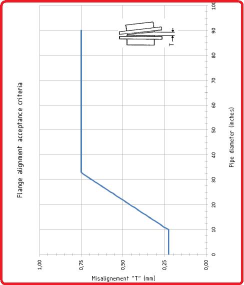
Before fixing the piping flanges on the machine flanges, planes have to be aligned in parallel as shown in Figure 1.
The difference between the maximum and the minimum distance will be a “T” misalignment value, to be checked with the acceptance criteria sheet (see Figure 1). After each adjustment, please check and record the measurements until an acceptable alignment is reached.
Fig. 1: Flange Alignment Acceptance Criteria
Clearance
Check the gasket type, material, and dimension. The distance between flanges should be just enough to insert the gasket by sliding it inside without causing any damage to it and the flange planes.
Concentricity
Check the dimensions of flange hold down bolts and align the relevant holes. Flange bolt holes have to be aligned within a maximum 3 mm offset, and in any case, when flanges are coupled, hold-down bolts should freely slide without any interference through holes.
Piping connections
Preliminary Tests:
Make a visual inspection of the coupled flanges. Surfaces should generally be in good condition; in particular, scratches in radial direction and oxidation are not admitted. As regards flange condition acceptance criteria and detailed prescriptions, please refer to ASME B16.47 and B16.5 procedures.
Connection Sequence
Pipes should not be firmly connected to the machine until final piping supports are installed. In order to avoid any undue stress, piping installation should never start by the machine flange side.
Elastic Support Check
Once the machine flange and piping flange tolerances have been checked, release the elastic supports by removing the locking pins, and make sure pipes remain in position (free to spring around the fixed position).
Connection References
While piping machine tightening activities are carried out, install dial gages on the machine legs in order to monitor any abrupt displacement and the alignment equipment too.
Pre-Tightening Operations:
Starting from one of the pipes to be connected, tighten the four tie rods (staggered tightening) between the machine flange and the relevant piping flange, until an intermediate torque is reached (70%-80% of the torque value indicated in the specification).
Remark: All operations executed until now have to be performed with the machine fixed on the base plate, in order to keep the required position according to the alignment specification.
Intermediate Alignment Check
Release the machine, by unscrewing the fixing screws of the machine axial keys, and by releasing washers (or Belleville washers). Check for any dial gauge range. Verify that the alignment has not changed.
– In case of small alignment variations, some adjustments are admitted only on the horizontal plane. If during the alignment correction, some elastic responses (spring effect) are sensed by the dial gages, it will not be possible to proceed with the final tightening, and piping restoration will be necessary.
– In case of considerable alignment variations it will not be possible to proceed with the final tightening, and piping restoration will be necessary.
Piping Restoration
Piping restoration operations shall consist in displacing pipes by acting on their supports, in order to eliminate forced assembling with the machine (cause of misalignment). If this operation is enough, cutting and welding of the piping will be necessary in order to correct its geometry.
Perform the same Pre-Tightening operations and checks, verify the Intermediate Alignment restoration for all remaining pipes to be connected, make sure the machine is always fixed on the skid during pre-tightening, and do release it before performing the alignment check.
Final Tightening
After reaching the pre-tightened piping condition (70%-80%) and machine-aligned condition, fix again the machine on the skid (by tightening the axial keys and the washers or Belleville washers). Proceed by tightening rods at the final torque values.
Alignment Check
After the final tightening, release the machine; verify the alignment and the DBSE between the machines you are working on and the adjacent machines.
Final Fixing
With the aligned machine and all pipes tightened at the required torque values, proceed with the final arrangement by fixing the machine and/to the skid, as follows:
– Fix the axial keys, with the required fixing screws, and furthermore (if possible /if foreseen) with welding points.
– Fix in the required position machine legs to the base plate (or to the proper supports on the base plate) by using the required pins.
– If calibrated washes are provided, make corrections in order to obtain the required clearance.
Final Alignment Check:
After the final tightening, please verify the Alignment.