Proper documentation of the stress calculation performed using Caesar II or any other stress analysis software is very important as the report or documents are the final deliverables to the client. So one should incorporate each and every detail of the analysis, assumptions if any, the basis of design, etc. in the final report. Every organization must have its standard format of reporting but the same changes slightly from project to project depending on client requirements. In this article, I will try to highlight major points which must be included in the final report before sending it to the client for approval.
Pipe Stress Analysis Report Front Page
Each final report starts with a very nice front page. The front page normally includes the project name; project no, client name with logo, PMC name with logo, and the performing organization or EPC consultant name with logo. It should also include the name of the stress system and the system number for which the report is prepared.
On the 2nd page normally it is better to include a table with revision details, name of performer, checker, and approver along with signature and report issue date. It informs the client about the responsible persons who are performing the analysis.
The next sheet or page should include brief content of all the major points with page numbers that are included in the report. From this page, the client will be able to know whether all relevant points are incorporated and considered in the analysis or not.
From the next page onwards, the actual analysis report of each stress system starts. Broadly the report should include the following major points:
Project Background: The project background can be included in 3-4 sentences highlighting the major points of the project. Many organizations use this as the starting point for the introduction part of the report. However, I personally do not prefer to include it.
Document Scope and Purpose: Every document must start stating the objective/ scope and purpose of the document. In this part, you can include the major system description. A typical objective is included here for your reference: “The main objective of this document is to furnish the findings of stress analysis performed on SYS-001 (Line 42”-P-YYYY-YYYY line routed from Tie-in YYYY to Tank (T-YYYY) inlet nozzle.” In a similar way, you can describe the system for which you are preparing the report.
Next, you can include a list of all abbreviations that you are going to use in the report. If you are not using abbreviated terms then this part is not required.
Now you have to include the lines which are included in that specific stress system. After including the major system lines, you can include the reference lines with the suffix REF (Ex. 18”-P-1235-REF).
Next, you have to include the names and numbers of all reference documents which are used in the analysis. Reference documents mean you should include the P&ID number with revision, line list number with revision, PMS number with revision, Equipment TAG and GA drawing number with revision, Any datasheet (PSV, Control Valve, etc.) number with revision, etc.
Assumptions and Consideration: The next part of the report is very important. Here you should mention all the considerations and assumptions if any. In a few points, you should mention all major highlights which can impact the stress system. A typical example of assumptions is shown below:
The ambient temperature considered is 21° C.
All systems have been analyzed for maximum and minimum design temperature cases. The operating temperature from the line list is not used in the analysis.
Caesar II configuration file “mm. fil” is used in the analysis.
Rigid body weights (flanges, valves, strainers, etc. as applicable) are considered from Caesar II database / Pipe Data Pro.
Control valve and PSV weights (wherever applicable) have been assumed suitably based on judgment where vendor data is not available.
Based on the YYYYYY project, YYYY has considered the Post Hydro test tank settlement value is assumed as 25 mm. All piping flanges have to be connected with tank nozzle flanges only after the tank hydro testing activity is finished.
Wind Analysis has not been performed as most of the lines are below 10 m elevation.
The existing part of lines has been modeled taking a reference from the existing PDMS 3D model. We have provided sufficient flexibility for a new line for arresting maximum thermal displacements where we could not find any guides/line stop in the existing line for proper boundary condition.
Conclusions: In this section, you should write in brief the conclusions which you have reached after the analysis. A typical example is shown in the below-mentioned bullet points:
Pipe Stresses are within the allowable limits (Refer to the attached Stress Summary Report)
Support loads are within the acceptable limits (Refer to attached Restraint Summary Extended Report)
Thermal Displacements and Sustained Sagging is within the acceptable limit (Refer to attached Restraint Summary Extended and Sustained displacement Reports)
Equipment nozzle loads are qualified with Vendor Allowable Loads in GA drawing/ relevant API standard (for pumps) as applicable (Refer to Nozzle Loading Details Sheet attached)
Supports at nodes YYY, ZZZ, and PPP are lifting in design temperature conditions. However, a separate hot sustained/lift-off file has not been made as the system is qualifying under Appendix P operating code stress check of ASME B 31.3. (Refer to attached Stress Summary Report).
Refer to marked-up stress isometrics for any stress recommendation.
Refer attached spring datasheets and SPS drawings for reference.
Load Cases used in Analysis: In the next section you can mention the load cases that you have considered for analysis. However, as all load cases will appear in the stress summary or restraint summary you can skip this part here.
Detailed Report Appendices: Now you are required to include the following reports from Caesar II. It is better to use an appendix for the same for proper demarcation. A typical method is shown here.
Attachments for Reference data: In the final part you should include the final marked-up stress isometrics and reference drawings in attachment form as shown below:
Attachment A: Marked-up stress isometrics.
Attachment B: P&ID drawing highlighting the system marked up
Attachment C: LDT/ Line List drawing highlighting the specific lines.
Attachment D: Equipment GA Drawings highlighting the nozzles and relevant data.
Attachment E: PMS
Attachment F: Caesar II plots for the overall system look.
Briefly, the above-mentioned points are sufficient for a complete report. However, if the client insists on any additional details you have to include the same along with the above-mentioned points. Hope now you will be able to prepare a complete report of the stress systems that you are performing.
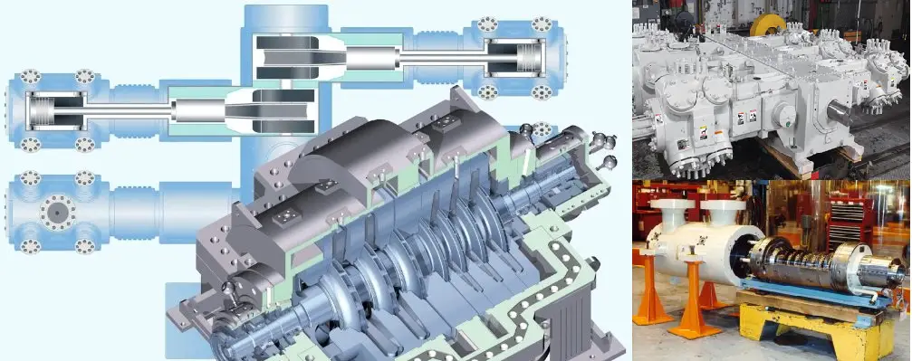
Difference Between Centrifugal and Reciprocating Compressor
Compressors are mechanical devices that increase the pressure of gases by reducing their volume. They are essential in a wide range of applications, including oil and gas industries, chemical and petrochemical industries, HVAC systems, industrial processes, and transportation. The choice between centrifugal and reciprocating compressors can significantly impact efficiency, cost, and operational performance. This article aims to comprehensively compare these two compressor types, helping readers understand which might be more suitable for their specific needs.
What is a Centrifugal Compressor?
A centrifugal compressor is a dynamic compressor with a radial design. The gaseous fluid enters the center of a rotating impeller with radial blades and is pushed toward the center by centrifugal force, which results in a rise in pressure and increases in kinetic energy. This energy is then converted into pressure by passing through a diffuser and volute. A centrifugal compressor is popularly used in Process Industries, Oil and Gas, Refineries, Wastewater treatment plants, etc. Single- or Multistage compressors are used depending on specific applications and industries.
Centrifugal compressors consist of a rotating impeller and a diffuser. The impeller, which is usually made of materials like aluminum or steel, rotates at high speeds, drawing in gas through the inlet. As the gas moves through the impeller, it gains kinetic energy, which is then converted to pressure energy in the diffuser.
Key Components:
Impeller: The heart of the compressor, responsible for adding energy to the gas.
Diffuser: Converts kinetic energy into pressure by slowing down the gas flow.
Volute: Collects the compressed gas and directs it toward the discharge.
A reciprocating compressor is a positive-displacement compressor that uses a cylinder and piston mechanism to compress the gas. The gas in the inlet section is compressed by the reciprocating motion of the pistons. Reciprocating compressors are used in refineries, gas pipelines, chemical and petrochemical plants, natural gas processing plants, and refrigeration plants.
Reciprocating compressors operate using a piston mechanism within a cylinder. The piston moves back and forth, creating a change in volume that compresses the gas. These compressors can be single-acting or double-acting, depending on whether the gas is compressed on one side or both sides of the piston.
Key Components:
Cylinder: Houses the piston and creates the compression chamber.
Piston: Moves to compress the gas.
Crankshaft: Converts rotational motion into the linear motion of the piston.
Difference between Centrifugal and Reciprocating Compressor
The major differences between centrifugal compressors and reciprocating compressors are provided below:
Differences in operating principles
Centrifugal Compressors
Centrifugal compressors operate based on the principles of fluid dynamics. The rotating impeller accelerates the gas, converting its velocity into pressure through the diffuser.
Steps in Operation:
Gas Inlet: Gas enters the impeller.
Acceleration: The impeller spins, imparting kinetic energy to the gas.
Pressure Conversion: The diffuser slows down the gas, converting kinetic energy into pressure.
Discharge: The high-pressure gas exits through the volute.
Reciprocating Compressors
Reciprocating compressors utilize the mechanical motion of a piston to compress gas.
Steps in Operation:
Intake Stroke: The piston moves down, creating a vacuum that allows gas to enter the cylinder.
Compression Stroke: The piston moves up, reducing the volume and increasing the pressure of the gas.
Discharge Stroke: The discharge valve opens, allowing high-pressure gas to exit the cylinder.
Differences of Reciprocating Compressors and Centrifugal Compressors in Performance Characteristics
Efficiency
Efficiency in compressors is a critical factor that affects operational costs and energy consumption.
Centrifugal Compressors: Generally exhibit high efficiency at large flow rates and are better suited for continuous operation.
Reciprocating Compressors: More efficient at lower flow rates but can become less efficient at high flow rates due to the mechanical complexities involved.
Pressure Ratio
The pressure ratio refers to the ratio of the discharge pressure to the inlet pressure.
Centrifugal Compressors: Typically achieve high pressure ratios, making them suitable for applications requiring significant pressure increases.
Reciprocating Compressors: Can achieve higher pressure ratios but usually require multiple stages to do so effectively.
Capacity Control
Capacity control is essential for adapting to varying demand.
Centrifugal Compressors: Often employ variable speed drives or inlet guide vanes for capacity control.
Reciprocating Compressors: Use unloading mechanisms, such as suction throttling, to control capacity.
Differences in Applications
Centrifugal Compressors
Centrifugal compressors are widely used in applications that require a continuous supply of gas at high flow rates. Common applications include:
HVAC Systems: Used in large chillers for cooling.
Gas Processing: In the petrochemical industry for gas transport.
Power Plants: For air supply in combustion processes.
Reciprocating Compressors
Reciprocating compressors are versatile and can be found in various applications, including:
Refrigeration: For both domestic and industrial refrigeration systems.
Gas Transportation: Used in natural gas pipelines for pressure maintenance.
Automotive: Employed in air conditioning systems in vehicles.
Differences between Centrifugal and Reciprocating Compressors in Terms of Advantages and Disadvantages
Centrifugal Compressors
Advantages:
High Efficiency: Especially at large flow rates.
Simple Design: Fewer moving parts, leading to lower maintenance needs.
Continuous Operation: Suitable for applications requiring constant airflow.
Disadvantages:
Limited Pressure Range: Less effective at low flow rates.
Cost: Typically higher initial investment compared to reciprocating compressors.
Reciprocating Compressors
Advantages:
Versatility: Can handle a wide range of pressures and flow rates.
High Pressure Capability: Excellent for applications requiring significant pressure increases.
Disadvantages:
Maintenance: More moving parts can lead to higher maintenance costs.
Pulsating Flow: May require additional components to smooth out gas flow.
Differences between Maintenance Considerations
Proper maintenance is essential for both types of compressors to ensure longevity and efficiency.
Centrifugal Compressors
Routine Inspections: Check for wear on impellers and diffusers.
Lubrication: Ensure proper lubrication of bearings and seals.
Vibration Monitoring: Regularly monitor vibrations to detect imbalances.
Reciprocating Compressors
Piston Inspection: Regularly check piston rings and cylinders for wear.
Valve Maintenance: Inspect and replace valves as needed.
Oil Changes: Frequent oil changes to ensure optimal lubrication.
Some additional differences between centrifugal and reciprocating compressors based on various parameters like maximum and minimum flow, inlet and outlet pressure, efficiency, compression ratio, discharge temperature, flow range, materials of construction, cost, etc. are listed below.
The comparison refers to the article titled: “What’s Correct for My Application – A Centrifugal or Reciprocating Compressor” by compression equipment specialists of Ariel Corporation: Paul Gallick – Senior Applications Engineer, Elliott Company; Greg Phillipi and Benjamin F. Williams.
The contents of the above article are produced in a tabular manner with minor modifications based on various other sources and the author’s own understanding.
Parameter
Centrifugal Compressor
Reciprocating Compressor
Maximum Flow
They can be sized for an inlet flow of 680,000 actual m3/h in a single body. Actual means at given suction pressure and temperature. The maximum flow through a centrifugal compressor is limited by the choke point, which is the point at which the flow through some part of the compressor nears a velocity of Mach 1.
The capacity of a reciprocating compressor is limited by cylinder size, the number of throws available, and the available driver speeds. A “throw” is a location on the crankcase where a compressor cylinder can be attached.
Minimum Flow
It is recommended that for flow rates of actual 300 m3/h and above, centrifugal compressors be critically evaluated for suitability. Unlike a reciprocating compressor where flow is solely a function of compressor geometry and speed, the minimum flow for a centrifugal compressor is limited by an aerodynamic condition known as surge, which is a function of compressor geometry, speed, aerodynamic gas conditions, and system resistance.
Similar to the maximum flow, the minimum flow in a reciprocating compressor is limited by the cylinder size, stroke, and speed. Reciprocating compressors of capacities of a few m3/h are available.
Minimum Suction (Inlet)Pressure
This can be atmospheric or sub-atmospheric (vacuum). For sub-atmospheric suction conditions, special seal and buffering designs are employed to prevent atmospheric air from being drawn into the compressor.
Can be atmospheric or vacuum. Where suction conditions involve sub-atmospheric pressures, adequate measures must be taken to prevent atmospheric air from leaking into the cylinder through the piston rod packing.
Maximum Discharge (Outlet) Pressure
For horizontally split compressors, discharge pressures up to 100 barg are common. For radially split (barrel) compressors, discharge pressures could go as high as 1000 barg.
Typical reciprocating compressors in the process industry are used to generate discharge pressures as high as 800 barg. Special compressors known as hyper compressors used in low-density polyethylene manufacture will generate pressures as high as 3500 barg.
Minimum Suction (Inlet) Temperature
Standard Centrifugal compressor materials are typically suitable for -20 to -50 deg C. Refrigeration compressors in ethylene service typically have temperatures as low as -100 deg C which require special low-temperature alloys. The lowest temperature requirement for centrifugal compressors is typically found in LNG boil-off gas applications. Minimum temperatures up to -170 deg C are required to be accommodated for this service and low-temperature alloy steels are employed as materials. Low-temperature seals and O-Rings are also required.
The common compressor cylinder materials, cast gray iron, and cast ductile iron are acceptable for use at temperatures as low as -40 deg C which typically occur in refrigeration applications. The lowest suction temperatures required typically are in LNG boil-off applications with requirements as low as -170 deg C and there are very limited manufacturers for this application.
Maximum Discharge (Outlet) Temperature
Maximum discharge temperatures are typically 200 to 230 deg C. Centrifugal compressors with higher temperatures can be manufactured but would require special designs such as center-supported diaphragms, less efficient seal materials, and high-temperature O-rings and sealants.
Discharge temperature limits will depend on the application (gas compressed) and the seal element materials selected. In hydrogen-rich gas applications, API 618 (2007) limits discharge temperatures to 135 deg C. For natural gas service, the maximum discharge temperature limit is 175 deg C. However, a more practical limit followed is 149 deg C. Air compressor discharge temperature limits may be as high as 200 deg C.
Flow Range (turndown)
The flow range of a centrifugal compressor is determined by the surge and choke points. Typical turndown for a fixed-speed, multi-stage centrifugal pump is approximately 20-30%. With variable speed drive or adjustable inlet guide vanes, the turndown can be increased to 40-50%.
Reciprocating Compressors have the ability to change flow through speed control, the addition of fixed clearance to a cylinder (fixed or variable volume clearance pockets), cylinder end deactivation, and gas recycling. The typical flow range might be from 100%, down to 20%, or even lower. The application will determine what type of capacity control method is required and used. On low compression ratio applications (compression ratio less than 1.6, such as pipeline transmission of natural gas) adding fixed clearance will hardly change the flow. Such an application may require speed control or cylinder end deactivation. In other applications with higher compression ratios, clearance pockets and cylinder end deactivation are commonly used to regulate flow.
Compression Ratio
For centrifugal compressors, the compression ratio is a function of gas molecular weight, compressibility factor, stage geometry, speed, and the number of compressor stages. For a specific gas, the limits to compression ratio are the mechanical and rotodynamic limitations on speed and the number of stages that can be accommodated in a single body. High discharge temperatures due to high compression ratios can usually be controlled by the intercooling between a compression stage.
The maximum compression ratio that a reciprocating compressor can handle in one stage is limited mostly by gas discharge temperature. The piston rod load generated by the compression ratio may also be a limit. Typical compression ratios for one stage are 1.2 to 4.0.
Compressed Gas Molecular Weight
The compression ratio is highly dependent on gas molecular weight. The head is developed by increasing gas velocity to create kinetic energy and then converting the kinetic energy to pressure in the diffuser. The amount of kinetic energy is a function of the gas velocity and gas molecular weight. Centrifugal compressors are used for a broad range of molecular weights including low molecular weight applications such as hydrogen recycling and high molecular weight applications using refrigerant gases with molecular weights over 100.
Reciprocating compressors are not limited by gas molecular weight. Both light and heavy gases are compressed very well. Over the range of molecular weight, different application configurations may be required. For example, very low molecular weight gases may present seal challenges and very high molecular weight gases may present challenges related to compressor efficiency.
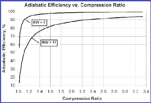
Efficiency
Polytropic efficiencies are used for centrifugal compressors rather than adiabatic efficiencies. In applications involving air compression adiabatic efficiencies are used. Typical polytropic efficiencies range from 70% to 85%. Efficiencies approaching 90% are possible. Efficiencies are primarily affected by internal leakage and mechanical losses.
Reciprocating compressors have a very characteristic adiabatic efficiency curve. Refer to the figure. As the compression ratio drops, adiabatic efficiency drops. Efficiency changes with molecular weight too. Other factors also impact efficiency, most significantly the compressor cylinder’s ratio of valve flow area to main bore diameter and piston speed.
Table 1: Centrifugal Compressor vs Reciprocating Compressors
Adiabatic Efficiency vs Compression Ratio
Parameter
Centrifugal Compressor
Reciprocating Compressor
Multiservice Capability
Typically, centrifugal compressors are not designed to handle a multitude of gases. Customized designs would be required that could handle different gases simultaneously.
Reciprocating compressors are very adaptable to a multitude of gases and can handle different gases at either the same stage or at different stages in the same machine. The number of different services on a given compressor crankcase (frame) is only limited by the throws available and the number of stages required for each service. 8, 10, and even 12 frames are not uncommon
Materials of Construction
Materials for major components such as casings, nozzles, shafts, impellers, etc. are primarily carbon steel, stainless steel, and/or alloy steel. Components may be cast, forged, or machined. Cast iron may be used for some stationary components. Material selection is primarily dependent on temperature, stress (pressure/torque), and gas composition (corrosive/erosive).
Reciprocating compressors are made of very common materials such as gray iron, ductile iron, carbon steel, stainless steel, and alloy steel. This could be in the cast, forging, or bar stock form. Some compressor pistons and covers may be made of aluminum. For corrosive applications, it is common to use stainless steel such as 17-4PH or 400 series for piston rods and compressor valve seats and guards.
Cost – Capital and Operating
The capital cost of a centrifugal compressor is typically higher than a reciprocating compressor operating under the same conditions. This is primarily due to the fact that centrifugal compressors require parts with more complex geometry, such as impellers and diaphragms. However, a centrifugal compressor has fewer wearing parts, resulting in lower operating costs in terms of replacement parts, repairs, and downtime.
For gas pipeline compression services where large centrifugal compressors (>7500 kW) are employed, using gas turbine drivers becomes economical compared to electrical motors when doing a cost evaluation in terms of capital and operating expenditure.
Generally, a reciprocating compressor will have a lower capital cost but a higher operating cost (excluding power consumption). For the same operating conditions, a reciprocating compressor will consume less power per unit volume flow. The reason for the higher operating costs is due to more wearable parts requiring frequent maintenance and leading to higher machine downtime. Compressor valves happen to be one of the most wearable parts in a reciprocating compressor.
Reliability
The reliability and availability of centrifugal compressors are typically 98 to 99%.
The reliability and availability of reciprocating compressors is typically 95 to 98%. Since reciprocating compressors have many more parts and more rubbing seals (pressure packing, piston rings, and rider rings) that wear and require more frequent replacement, they are considered somewhat less reliable than centrifugal compressors. Another reciprocating compressor component is compressor valves (simple spring-loaded check valves) which require frequent maintenance and replacement
Typical Maintenance Intervals
In clean gas service and without much variation in operating conditions, a centrifugal compressor can operate continuously for 10 years or longer. Maintenance requirements are typically limited to replacing bearing pads and seal-wearing parts.
Maintenance requirements for reciprocating compressors vary significantly with the application and follow maintenance patterns very much based on what has been described in the reliability section. Compressor valve and seal elements may require to be maintained in durations as short as a few months and as long as 3-5 years. Major machine overhaul including bearing replacement may be required after 10 years of operation or longer.
Installation Time and Complexity
The installation time varies widely depending on the size of the compressor. The number of main casing nozzles and the type of driver (electric motor/gas or steam turbine) also affect installation time. Location can also be a factor. Remote or offshore locations can add to installation time. The compressor and driver are typically packaged on a base plate complete with oil piping and wiring to junction boxes. Process equipment such as scrubbers, and coolers and process control valves are typically installed at the site. Auxiliary systems such as lube oil consoles, control panels, and seal buffer systems may also be installed separately. Piping and wiring from these auxiliary systems and process equipment to the compressor train are typically done at the site. Installation time for a typical motor / gear-driven compressor package is 2-3 weeks. For a very large compressor or a gas turbine-driven compressor, the installation time could be as high as 6-8 weeks.
Installation time for a reciprocating compressor varies significantly with site and location, and whether or not the compressor is packaged. Packaged compressors up to 3.4 MW and of a high-speed short-stroke design are common today. Installation time for these might vary from a few days to a couple of weeks. Larger slow speed long stroke compressors assembled at the site might require 3 to 4 weeks to install
Lead Time
Lead time for a centrifugal compressor train range from 35 to 75 weeks. Often the lead time is governed by the driver (electric motor/turbine) since these are generally made to order. Special metallurgy and/or special design requirements of compressor components significantly add to the lead time.
Lead time for a bare compressor will vary from 14 to 40 weeks depending on size and manufacturer. Electrical motor-driven reciprocating compressors may require longer lead times specifically if large high-horsepower motors are required. For reciprocating gas engine-driven large compressors the lead times may be shorter
Table 2: Reciprocating Compressor vs Centrifugal Compressors
What is Category M Fluid Service for Process Piping Design?
While referring ASME B31.3 code we come across various types of fluid services. In day-to-day engineering design activities, we normally design and construct systems following the rules of Normal Fluid service. Category M fluid service is different from normal fluid service. As defined in clause 300.2 of ASME B31.3 Category M Fluid Service is a fluid service in which both of the following two conditions apply:
the fluid is so highly toxic (poisonous
or lethal) that a single exposure to a very small quantity of the fluid, caused
by leakage, can produce serious irreversible harm to persons on breathing or
bodily contact, even when prompt restorative measures are taken.
after consideration of piping
design, experience, service conditions, and location, the owner determines that
the requirements for Normal Fluid Service do not sufficiently provide the leak
tightness required to protect personnel from exposure.
Chapter VIII of ASME B31.3 code provides rules for piping designated by the owner as being in Category-M Fluid Service which means It is the owner’s responsibility to select the fluid service category. Selections of Category D or Category M cannot be made without the owner’s permission.
Also note that it is Category M Fluid Service and not Category M fluids, as it is not simply the fluid, but also the conditions of installation that are considered in making the designation. The owner is guided in the classification of the piping system by the definition of Category M Fluid Service in Chapter I of ASME B31.3. Additionally, a guide to the application of these rules is provided in ASME B31.3, Appendix M, which contains a flow chart to assist the owner in classifying fluid services. This Appendix is considered by the Code to provide guidance, not Code requirements.
It is not possible to create a list of Category M fluids, because the conditions of the installation must be considered in making the classification. For a fluid service to be Category M, the potential for personnel exposure must be judged to be significant. If piping is double-contained, for example, it could be judged that even highly toxic fluids (such as methyl isocyanate, phosgene, or nerve gas) do not make the system Category M, because the potential for personnel exposure is not significant. For Category M fluid service, the rules for Normal Fluid Service are not applicable. Instead, additional rules that lead to more costly construction, with provisions designed to enhance piping system tightness, are provided in Chapter VIII.
If higher
integrity piping is desired by the owner, even though the fluid service does
not meet the definition of Category M, the owner can still specify the
additional design, construction, examination, and testing requirements that are
provided in Chapter VIII. Hydrofluoric acid is one example of a fluid for which
many owners specify more stringent requirements than are provided in the Code
for Normal Fluid Service, although it actually would be considered Normal Fluid
Service.
Normally the
following should be applicable for Category M fluid services.
Use of any temperature other
than the fluid temperature as the design temperature shall be substantiated by
heat transfer calculations confirmed by tests or by experimental measurements.
Design, layout, and operation
of piping shall be conducted so as to minimize impact and shock loads.
Suitable dynamic analysis, such as computer simulation, shall be made where necessary to avoid or minimize conditions that lead to detrimental vibration, pulsation, or resonance effects in the piping.
Allowance for Pressure and
Temperature Variations, Metallic Piping is not permitted.
Valves having threaded bonnet joints (other than union joints) shall not be used.
Special consideration shall be given to valve design to prevent stem leakage into the environment.
Bonnet or cover plate closures and body joints shall be flanged and secured by at least four bolts with gasketing.
Single-welded slip-on flanges, expanded-joint flanges, slip-on flanges used as lapped flanges, and threaded metallic flanges, except those employing lens rings or similar gaskets and those used in the lined pipe where the liner extends over the gasket face, shall not be used.
Split backing rings shall not
be used.
Socket welded joints greater
than DN 50 (NPS 2) are not permitted.
Caulked joints shall not be
used.
Soldered, brazed, and braze welded joints shall not be used. adhesive joints and bell-type joints shall not be used.
Relief set pressure shall be in
accordance with ASME BPVC, Section VIII, Division 1.
The maximum relieving pressure
shall be in accordance with Section VIII, Division 1.
Materials of unknown
specification shall not be used.
A piping system designed for Category M service fluid preferably shall not go under severe cyclic conditions
Process Safety Management (PSM) is the management of hazards that can give rise to major accidents involving the release of potentially dangerous materials, the release of energy (such as fire or explosion), or both. It focuses on the prevention of leaks, spills, overpressure, equipment malfunction, excessive temperatures, metal fatigue, corrosion, and other similar conditions by the application of good engineering and design principles. In short, Process Safety Management focuses on controlling the release of highly hazardous substances. All plants handling highly hazardous materials must undergo a sound Process Safety Management program.
Functions of Process Safety Management
The foundation of a process safety management system is to manage risks and reduces them to a tolerable level, either by reducing the likelihood of the hazard release, reducing the consequences if does get released, or both. So, basically, process safety management is a blending of management and engineering skills to prevent catastrophic accidents. The main functions of process safety management are:
the proactive and systematic identification of unsafe releases
evaluation and mitigation or prevention of chemical releases
A sound Process Safety Management will ensure minimal risk from:
Fire
Explosion
Poisoning, and
Suffocation
Written procedures for managing those hazardous releases must be developed and implemented from the design stage itself to ensure proper process safety management.
The US Occupational Safety and Health Administration (OSHA) has issued a Process Safety Management standard “29 CFR 1910.119” for helping chemical companies to identify highly hazardous chemicals and take precautionary action for ensuring a safe and healthy workplace.
What is Process Safety?
Process Safety is defined as “a discipline that focuses on the prevention of fires, explosions, and accidental chemical releases at chemical process facilities”. So it is a disciplined framework for managing the integrity of operating systems and processes that handle hazardous substances. It relies on good design principles, engineering, and operating and maintenance practices. It deals with the prevention and control of events that have the potential to release hazardous materials and energy. Such events don’t only happen at chemical facilities, they occur in refineries, offshore drilling facilities, petrochemical plants, solids handling facilities, water treatment plants, ammonia refrigeration plants, off-shore operations, etc.
Why is Process Safety important?
Process safety hazards can give rise to major accidents involving the release of potentially dangerous materials, the release of energy (such as fires and explosions), or both. Process safety incidents can have catastrophic effects and can result in multiple injuries and fatalities, as well as substantial economic, property, and environmental damage.
Process safety refinery incidents can affect workers inside the refinery and members of the public who reside nearby. Process safety in a refinery involves the prevention of leaks, spills, equipment malfunctions, over-pressures, excessive temperatures, corrosion, metal fatigue, and other similar conditions. Process safety programs focus on the design and engineering of facilities, hazard assessments, management of change, inspection, testing, and maintenance of equipment, effective alarms, effective process control, procedures, training of personnel, and human factors.
Several Major incidents in both the upstream and downstream industries have highlighted the importance of having robust processes and systems in place. A major incident is typically initiated by a hazardous release; it may also result from a structural failure or loss of stability that escalates to become a major incident. For the oil and gas industry, the emphasis of process safety and asset integrity is to prevent unplanned releases which could result in a major incident.
We cannot afford to rely solely on lessons from major process incidents, which happen relatively infrequently. To strengthen safety barriers and prevent these incidents from occurring at all, it is necessary to collect, collate and analyze data from less severe incidents and shortfalls in management system performance. Process safety is required as Failures of process safety management systems are deadly and costly. It impacts people, communities, assets, and the environment.
What is Process Safety Engineering?
Process safety
in Design Engineering means
Prevention and mitigation of incidents
Identifying Safety-critical equipment and linking them to performance standards
Compliance with applicable standards
Properly design, procure, build, install and test
Hand over safe facilities
Engineering process safety emphasizes existing good practices to reduce unsafe acts and conditions. It guides daily actions one can take to prevent these incidents from happening again.
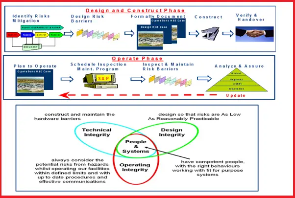
The following image briefly explains the bare minimum steps to follow for process safety in engineering.
Elements of Process Safety Management
To manage chemical operations involving hazardous materials; Process Safety Management must be implemented. The main elements of Process Safety Management are
Technology,
Design and Engineering Facilities
Hazard Assessment
Management of Change
Regular Inspection and Testing
Equipment Maintenance
Effective Alarm Management
Implementation of process control,
Proper operating procedures
Maintaining all regulatory requirements
and Human factors.
Reasons for Process safety management
There are numerous reasons to implement process safety management in plants. The main reasons are:
Prevention of major accidents and potential impact of the same.
Managing the risks inside the plant.
increasing sustained value and boosting productivity.
produce a high-quality product at less cost.
Increasing profit.
Keeping the environment safe.
increase shareholder value.
So the main role of process safety management is to keep the hazard under control inside the equipment or pipes that are designed and maintained to handle them safely. It requires a commitment from design, engineering, operation, and maintenance personnel to follow all the roles without deviation.
Fundamental Questions for Safety Management Process
To reduce or manage the process safety risk inside a plant one must ask the following four fundamental questions:
What can go wrong?
Are proper controls in place if a major incident occurs?
What does each control deliver in terms of a “safety outcome”?
Is it confirmed that the controls will work as intended?
Process Safety Management Process
A sound process safety management can be achieved by ensuring the following:
Design Integrity
Technical Integrity, and
Operating Integrity
Design Integrity:
Design integrity ensures the integrity of all activities prior to commissioning. This leads to
compliance with the design and engineering standards
robust assurance process during the EPC phase.
design HSE cases
to identify the maintenance routine for Safety-Critical Equipment.
written Design and Operating philosophy
with clear agreement on maintenance and inspection strategies.
Technical Integrity:
It means the safeguarding of assets through effective maintenance, inspection, repair, and assurance that can be achieved through
In the piping and plumbing industry, a piping nipple is a pipe fitting, consisting of a short straight piece of pipe, usually provided with male pipe thread at both ends, for connecting two other female threaded fittings or pipes. It is one of the most popular categories of pipe fittings. Pipe Nipples are commonly used as adapters from one connection type to another.
Pipe nipples are mainly used in low-pressure piping systems. They are used to fit straight-end hoses or pipes. The working pressure of pipe nipples will vary with the size and construction of the pipe, temperature, and product being conveyed. Pipe nipples are available in the widest variety of wall thicknesses and materials in the industry.
Pipe nipples are fabricated by cutting a specified length of pipe and applying the desired end connections. The pipe nipple dimensions and material follow pipe specifications based on ASME code B16.11. Pipe nipples come in seamless, threaded, grooved, barbed, bent, or welded construction.
Applications of pipe nipples
Pipe nipples as pipe fittings in a wide variety of industrial applications like:
Oil & Gas
Chemical processing industries
Petrochemical
Pharmaceutical
Food & beverage
Pulp & paper
Shipbuilding/marine
Waste incineration
Machine building
Architectural
Semiconductor etc.
Pipe Nipple Ordering Information
When ordering pipe nipples, the following properties must be specified:
Technical Specifications like Pressures, Temperatures, Safety coefficients, Conformity to the standards, Certifications, Standard, Double duty, Extra duty, Extra double duty, etc.
The length of the pipe nipple is usually specified by the overall length including threads. Pipe Nipples can come in any specified length, but most commonly range between close to 12”. A close pipe nipple is the shortest piece of pipe necessary to allow for fully threaded end connections, where there is no smooth surface between threads. Threads used on nipples are BSP, BSPT, NPT, NPSM, and Metric.
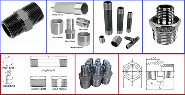
Types of Pipe Nipples
There are
several different types of pipe nipples in common use. A short list includes:
Barrel Nipple
Close Nipple / Running Nipple
Hexagonal Nipple
Reducing Nipple / Unequal
Nipple
Hose Nipple
Welding Nipple
Swage Nipple
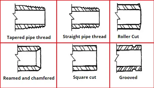
Fig. 1: Various types of Piping Nipples
Swage nipple
The basic purpose of a swage nipple is to bring the flow of fluids from one pipe size to another. These are available with plain, beveled, or threaded ends.
Close Nipple / Running Nipple
In its most basic form, a pipe
nipple is a short length of pipe with male pipe threads at both ends for
connecting other fittings. Generally, there is a short distance of unthreaded
pipe between the two threaded ends, depending on how far apart you need the
attached fittings to be. When there is no unthreaded pipe between the two
connecting ends, the pipe nipple is called a “close nipple” or a “running
nipple”. In that case, connected fittings come close to touching one another
and very little of the nipple can be seen.
Close nipples are difficult to
work with. A close nipple can only be unscrewed by gripping one threaded end
with a pipe wrench which will damage the threads and necessitate replacing the
nipple, or by using a specialty tool known as a nipple wrench which grips the
inside of the pipe, leaving the threads undamaged.
Hexagonal Nipple
In pipe nipples where there is a little space between both the threaded ends, there may have a hexagonal section in the center for a wrench to grasp the nipple. These nipples are called “hexagonal nipples”. This hexagonal section in the middle functions like a nut that can be gripped by a normal wrench, providing a greater mechanical advantage than a normally rounded pipe nipple. A hexagonal nipple with more distance between the threaded ends is called a “long hex nipple”.
Reducing Nipple / Unequal Nipple
For ping systems that require a change in pipe dimension, “reducing nipple” or “unequal nipple” is used. Reducing nipple takes a female fitting with a larger connection and attaches it to a smaller one. Care should be taken when using these parts since a reduction in pipe diameter can mean more pressure and a greater flow rate in the smaller pipe/fitting.
Hose Nipple
For piping systems that require pipe connection to tubing, a “hose nipple” is used. A hose nipple features a male threaded connection on one end and a hose barb on the other end. The hose barb may be the same size as the pipe connection or it may be of reduced size.
Welding Nipple
For piping systems that require to be connected to welded pipes or fittings, a “welding nipple” is used. The welding nipple has a threaded connection on one end and a normal cut pipe at the other end. The unthreaded end of the pipe provides more surface area for the use of welding materials to make a stronger connection. One main benefit of welding nipples is that once the unthreaded end is connected, connecting pipes or other fittings to the threaded end becomes much easier.
Pipe Nipple End Connections
The end connections need to be specified by the customer as well;
Plain Both Ends (PBE), Threaded Both Ends (TBE), Bevelled Both Ends (BBE), Threaded One End (TOE), Bevelled One End (BOE), Plain One End (POE), or a combination thereof, depending on the ends of the piping system into which the pipe nipple will be fitted.
A Plain Both Ends (PBE) pipe nipple, has both ends as plain ends, with no thread, typically used to fit a socket weld connection.
A Threaded Both Ends (TBE) pipe nipple has both ends as threaded ends and is used to fit female threaded connections.
A Bevelled Both Ends (BBE) pipe nipple has both ends as bevel ends and is used for welding purposes like a buttweld fitting.
A Heat exchanger is a device to transfer heat from one fluid (Liquid/Gas) to another. There are various types of heat exchangers used in process piping. Shell and Tube heat exchanger is the most common type of heat exchanger. This article will provide you with a guide to everything you need to know about shell and tube heat exchangers. The major topics covered in this article are:
Definition of Shell and Tube Heat Exchanger
Working Principle of Shell and Tube Heat Exchanger
Basic Components and Parts
Types of Shell and Tube Heat Exchanger
Codes and Standards for Shell and Tube Heat Exchangers
Design of Shell and Tube Heat Exchangers
And much more.
What is a Shell and Tube Heat Exchanger?
Shell and tube heat exchanger (STHE) is the most widely used heat exchanger and is among the most effective means of heat exchange. A shell and tube heat exchanger is a device where two working fluids exchange heat by thermal contact using tubes housed within a cylindrical shell. The fluid temperature inside the shell and tube are different and this temperature difference is the driving force for temperature exchange. Used for wide temperature and pressure ranges, Shell and tube heat exchangers are compact in design, easy to construct and maintain, and provide excellent heat exchange.
As the name specified, it consists of a shell and a number of tubes. The shell is the housing of the exchanger and tubes are mounted inside the cylindrical shell.
Working Principle of Shell and Tube Heat Exchanger
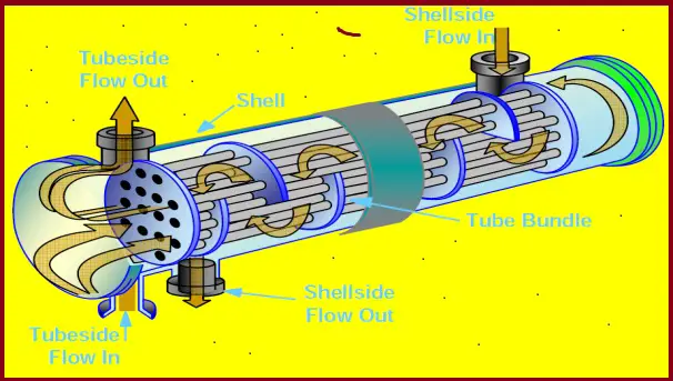
The working of a shell and tube heat exchanger is fairly simple. One fluid flows inside the tubes and the other through the shell. While flowing they exchange heat which means the cold fluid gains the heat from the hot fluid. So one cold fluid enters the shell (or tube side or channel side) inlet nozzle and comes out of the outlet nozzle as hot fluid. Obviously, the other fluid will become colder in the outlet than in the inlet. The heat transfer in a shell and tube heat exchanger is determined by the exposed surface area and is decided by the number of thermally conductive metal tubes. The fluid flow inside the shell and tube heat exchanger can be parallel flow or crossflow.
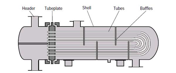
Fig 1 shows the typical working principle of a shell and tube heat exchanger.
Fig. 1: Working principle of a Typical Shell and Tube Heat Exchanger
The above figure shows both the inlet and outlet nozzle in the front header of the channel side. That means this exchanger consists of an even number of tube passes. However, there can be an odd number of tube passes. In that situation, the channel side outlet nozzle will be on the read header. Increasing the number of tube passes increases the heat transfer coefficient.
To increase the fluid turbulence in the tube and shell side flow, turbulators and baffles are installed inside tubes and shells respectively. This increases the heat transfer between the fluids.
Basic Components of Shell and Tube Heat Exchanger
Typically a Shell and Tube Heat Exchanger consists of two-compartment / sections; one is shell side and the other is channel/tube side
The shell side section consists of the following components: Shell, Cover, Body Flange, Nozzles, and Saddle support.
Channel / Tube side section consists of the following components: Channel, Cover, Body Flange, Nozzles, Tube Sheet, and Tubes (Tube Bundle)
Fig. 2: Components of a Shell and Tube Heat Exchanger
The heat exchanger is supported by saddles in the shell part.
Tube Bundle of Shell and Tube Heat Exchanger
Tube Bundle (Fig. 3) consists of the following components
Tube sheet
Tubes
Baffles
Tie rods and Spacers
Sliding strips
Tube bundles are removed during maintenance. Standard practice is to flow the corrosive fluid inside the tubes so that if corroded they can be easily replaced or repaired. Fig. 3 below shows a typical tube bundle.
Fig. 3: Typical tube bundle of a shell and tube heat exchanger
Tube Pattern inside Shell & Tube Heat exchanger
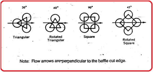
Normally tubes inside the exchanger are 0.5″ to 2″ in size and arranged in triangular or square patterns as shown in Fig. 4
Fig. 4: Typical tube patterns
Tube Pitch
The tube shall be placed with a minimum center-to-center distance of 1.25 times the tube outside diameter of the tube. When mechanical cleaning of the tube is specified then a minimum cleaning lane of 6.4 mm shall be provided.
Baffles
Baffles are installed in the shell of the shell and tube heat exchanger to create more turbulence and increase the flow time so that better heat exchange is possible. Baffles support the tubes so that damage and vibration of tubes are minimized.
Types of Shell and Tube Heat Exchangers
TEMA shell and tube heat exchanger types based on application
Class R Exchangers – Refinery and Petrochemical Application
Class C Exchangers – General Process Application
Class B Exchangers- Chemical Process Application
TEMA Shell and Tube Heat Exchanger Applicable Criteria
Inside diameter less than 2540 mm (100 inches)
Product of nominal diameter (mm) and design pressure (kPa) of 17.5 x 10⁶
Design pressure of 3000 psig (20684 KPa)
The reason behind such limitation is to keep the maximum shell wall thickness below 3 in. (76 mm), and the maximum stud diameter below 4 in. (102 mm).
Shell and Tube heat exchanger types based on construction
Depending on various construction and configuration parameters following types of shell and tube heat exchangers are widely used in industries.
Fixed Tube Sheet Heat Exchanger
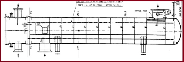
The tube sheet is fixed in the shell by welding and hence the term fixed tube sheet exchanger applies. This simple and economical construction allows the cleaning of the tube bores by mechanical or chemical means. An expansion bellow is installed in the shell when there is a large temperature difference between the shell and tube materials. Refer to Fig. 5 for an example of the fixed tube heat exchanger.
Fig. 5: Example of a typical fixed tube heat exchanger
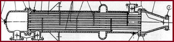
Floating Head Heat Exchanger
In floating head construction, the rear header can float or move as it is not welded to the shell. The tube bundle can easily be removed during maintenance. Fig. 6 shows an example of a floating head heat exchanger.
Fig. 6: Example of a typical Floating Head Removable bundle heat exchanger
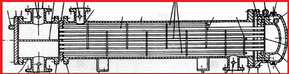
Stationary Tube sheet with removable tube bundle
Fig. 7 shows an example of a stationary tube sheet with a removable tube bundle.
Fig. 7: Example of a typical stationary tube-sheet type heat exchanger
U-tube Heat exchanger
U-tube exchangers are a type of shell and tube heat exchanger whose tube bundle is made of continuous tubes bent into a “U” shape. The bend side is free-floating and this helps in thermal expansion without requiring expansion joints. However, such bends are difficult to clean.
Fig. 8: Typical representation of U-tube Heat exchanger
Based on the number of times the tube-side/shell-side flows pass through the exchanger, the shell and tube heat exchanger is categorized as:
Single-Pass exchangers and
Multi-Pass exchangers
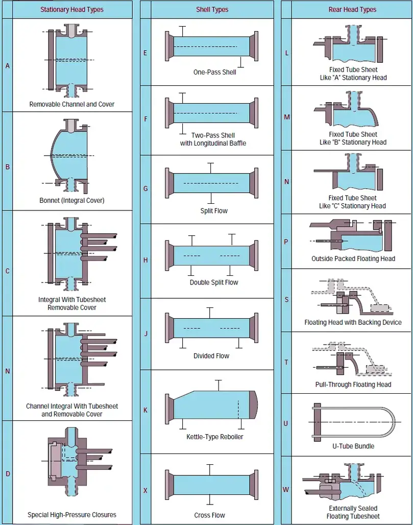
The full TEMA classification of shell and tube heat exchanger types is provided in Fig. 9 below:
Fig. 9: TEMA Shell and Tube Heat Exchanger types
Depending on the application of shell and tube heat exchangers, they are known as various types as listed below:
In this, two or three heat exchangers are placed one above the other. This is termed as 1 shell in parallel and 2 or 3 Shells in series. Refer to Fig. 10.
Fig. 10: Figure showing stack arrangement of heat exchangers
Codes and Standards for Shell and Tube Heat Exchangers
The following codes and standards govern the design of shell and tube heat exchangers.
API 660 ( Shell and Tube heat exchangers for general refinery service)
ISO 16812
ASME SECT.VIII Div.1 (UHX) or Div.2
PD 5500
EN 13445
AD 2000 Merkblatt.
TEMA -Tubular Exchanger Manufacturers Association
Shell DEP 31.22.20.31 and DEP 31.21.01.30
Design of Shell and Tube Heat Exchangers
Process Design of Shell and tube Heat exchanger
The design of the Shell and tube heat exchanger is a trial-and-error iterative process. In recent times, thermal design has been carried out by the process team using engineering software. However, the logic behind the calculations should be clearly understood. The shell and tube heat exchanger design calculations are based on the initial selection of a preliminary exchanger configuration and certain initial decisions like
the front and rear header type,
shell type,
the sides the fluids are allocated,
baffle type and baffle pitch
tube diameter, length, and tube layout
shell diameter, and
number of tube passes
Further steps for the shell and tube heat exchanger design consist of
Calculation of shell side flow distribution and heat transfer coefficient
Estimation of tube side heat transfer coefficient and pressure drop
Determination of wall resistance and overall heat transfer coefficient
Calculation of Mean temperature difference (log mean temperature difference) from the inlet and outlet temperatures of the two fluids.
Estimation of the required heat transfer area
Comparison of the calculated area with the assumed geometry
Comparison of shell and tube-side pressure drop with allowable pressure drop
If the pressure drop is within the allowable pressure drop design is acceptable. Otherwise, adjust the assumed geometry and repeat the above steps.
Once the requirements are met, a process datasheet is developed indicating all process design parameters of shell and tube heat exchanger design.
General design Considerations for shell and tube heat exchanger
Fluid Allocation: Shell Side vs. Tube Side
The following table (Table 1) provides general guidelines for shell and tube side fluid allocation in a shell and tube heat exchanger:
Fluid Parameters
Fluid Allocation-Shell Side
Fluid Allocation-Tube Side
High-Pressure Fluid Stream
X
Corrosive Fluid
X
High-fouling fluid stream
X
More Viscous fluid
X
Lower Flow Rate Fluid
X
Fluid with a low heat transfer coefficient
X
Toxic Fluid
X
Table 1: Shell and Tube-side Fluid Allocation
Fluid Velocity inside Shell and Tube
High fluid velocities increase heat transfer coefficients and reduce fouling but cause erosion and increase pressure drop. So velocity selected should be just enough to prevent the settling of suspended solids. Typical fluid velocities considered for the design of shell and tube heat exchangers are given in the following table (Table 2):
Fluid Types
Fluid Velocity-Shell Side
Fluid Velocity-Tube Side
Liquid
0.3 to 1 m/s
1 to 2 m/s
Gas /Vapor (Vacuum Pressure)
50 to 70 m/s
50 to 70 m/s
Gas /Vapor (Atmospheric Pressure)
10 to 30 m/s
10 to 30 m/s
Gas /Vapor (High Pressure)
5 to 10 m/s
5 to 10 m/s
Table 2: Typical fluid Velocities in Shell and Tube Heat Exchanger Design
Pressure Drop Consideration
Typical pressure drop values considered for shell and tube heat exchanger design are:
For liquids with Viscosity=1 to 10 mN- s/m2, ΔP= 50-70 kPa
Liquids without phase change= 70 kPa
Condensing streams= 14 kPa
For Vapor and gas services:
High vacuum Pressure: 0.4-0.8 kPa
Medium vacuum Pressure: 0.1 x absolute pressure
Pressure 1 to 2 bar: 0.5 x system gauge pressure
Pressure above 10 bar: 0.1 x system gauge pressure
Vapors without phase change= 14 kPa
Boiling Streams = 7 kPa
Software used for Thermal Design
The most popular software used for the thermal design of shell and tube heat exchanger are listed below
HTRI – Heat Transfer Research Institute
HTFS – Heat Transfer Research and fluid flow service
Mechanical design of Shell and Tube Heat exchanger
Mechanical design of shell and tube heat exchangers consists of calculation of shell thickness, flange thickness, etc. Various codes like ASME Sec VIII, PD 5500, TEMA, etc. provide guidelines for mechanical design. The following design guidelines can be followed:
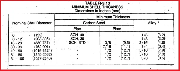
Minimum Shell Thickness (Fig. 11) as per TEMA for Class – R
Fig. 11: Minimum Shell thickness of shell and tube heat exchanger
Baffle clearance, Baffle spacing, and thickness as per TEMA table RCB -4.3
Tie rod size and nos. as per TEMA table R- 4.71 for class – R
Peripheral Gasket: The minimum width of the peripheral ring gasket for external joints shall be 10 mm for shell sizes up to 584 mm and 12 mm for all larger shell sizes.
Pass Partition Gasket: The min. width of the gasket web for the pass partition of the channel shall not be less than 6.4 mm for shell sizes up to 584 mm and 9.5 mm for all larger shell sizes. The gasket joint shall be confined type
Shell and Head design is done as per selected Pressure Vessels Design Code such as ASME, EN, or AD
The most widely used design code across the world is ASME Sect. VIII Div.1 & 2
Body / Girth Flange Design as per Appendix -2 of ASME Sect. VIII Div.1
The tube sheet design is Mandatory as per UHX of ASME Sect. VIII Div.1
The tube sheet is designed for the following three cases.
Tube side pressure (Pt) acting and Shell side pressure (Ps) is Zero
Shell side pressure (Ps) acting and Tube side pressure (Pt) is Zero
Shell side pressure (Ps) acting and Tube side pressure (Pt) acting
Please consider the effect of Vacuum in the above load cases
Tube sheet Design formula based on the theory of Flat Plates
Shell and Tube Heat Exchanger Material of Construction (MOC)
The following materials are the most common as Shell and Tube Heat Exchanger MOC.
Carbon steel and Cladding Plates
Stainless Steel
Duplex Stainless steel
Tubes – Carbon steel, Stainless steel, Duplex stainless steel, Exotic material such as copper, Inconel, Titanium
Maintenance of Shell and Tube Heat exchangers
Depending on user experience and manufacturer guidelines, shell and tube heat exchangers should be inspected at regular intervals. A shell and tube heat exchanger can fail by one or more of the following factors:
Improper design.
Excessive fouling.
Air or gas binding resulting from improper piping installation or lack of suitable vents.
Excessive clearances between the baffles and shell and/or tubes, due to corrosion.
Operating conditions differ from design conditions.
Maldistribution of flow in the unit, etc
Following preventive maintenance steps at regular intervals can reduce the risk of equipment failure. Following maintenance steps can be followed to enhance shell and tube heat exchanger performance:
Cleaning periodically to avoid fouling
Inspection of tubes
Gasket replacement
Repairing leaks if detected during inspection.
Application of Shell and Tube Heat Exchangers
Shell & Tube Heat Exchangers find their application in the following Industries-
Refinery and Petrochemical
Fertilizer
Oil and Gas
Chemical
Power Plants
Advantages of Shell and Tube Heat Exchanger
Shell and tube heat exchangers are widely used in various industrial processes due to their numerous advantages. These advantages make them a preferred choice for many applications where efficient heat transfer is essential. Here are some of the key advantages of shell and tube heat exchangers:
High Heat Transfer Efficiency: Shell and tube heat exchangers are known for their excellent heat transfer capabilities. The design, which features a large surface area for heat exchange, allows for the efficient transfer of thermal energy between the fluids. This results in rapid heating or cooling, making them highly efficient in heat transfer applications.
Versatility: Shell and tube heat exchangers are versatile and can handle a wide range of fluids, including gases and liquids. They can be used for both heating and cooling processes and are compatible with various industries, including chemical processing, power generation, food and beverage, and HVAC systems. They are available in a range of configurations to suit various operations.
Robust and Durable Construction: These heat exchangers are typically built with materials like stainless steel, copper, or titanium, which offer excellent resistance to corrosion and wear. This durability ensures a long operational lifespan, reducing maintenance and replacement costs.
Ease of Maintenance: Shell and tube heat exchangers are relatively easy to maintain. The tube bundle can be accessed and cleaned or replaced without the need to disassemble the entire unit. This feature minimizes downtime and reduces maintenance costs.
Compact Design: Despite their high efficiency, shell and tube heat exchangers have a compact design, which is particularly beneficial in applications with limited space. Their compactness allows for efficient heat transfer within a relatively small footprint.
High Pressure and Temperature Capabilities: Shell and tube heat exchangers are capable of handling high-pressure and high-temperature applications. This makes them suitable for use in industries such as oil refining and chemical processing, where extreme conditions are common.
Customizable Configurations: These heat exchangers can be customized to meet specific requirements. Engineers can adjust the number of tubes, tube diameter, tube arrangement, and other design parameters to optimize performance for a particular application.
Resistance to Fouling: The design of shell and tube heat exchangers often includes baffles and turbulence-inducing features, which help reduce fouling by preventing the buildup of deposits on the tube surfaces. This resistance to fouling ensures consistent heat transfer efficiency over time.
Long Service Life: When properly maintained, shell and tube heat exchangers can have a significantly long service life, making them a cost-effective investment for industries that rely on continuous heat exchange operations.
Energy Efficiency: Their high heat transfer efficiency translates into energy savings. Shell and tube heat exchangers can help reduce energy consumption in processes that require heating or cooling, contributing to overall operational cost reductions.
Disadvantages of Shell and Tube Heat Exchanger
While shell and tube heat exchangers offer numerous advantages, they also have some disadvantages and limitations. It’s essential to consider these drawbacks when selecting a heat exchanger for a specific application. Here are some of the disadvantages of shell and tube heat exchangers:
High Initial Cost
Large Footprint
Limited Heat Transfer for Low Temperature Differences