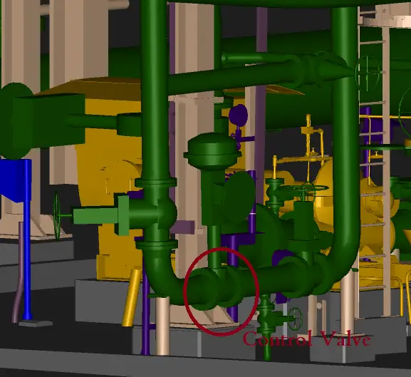
Control valves are control devices that are used to manage and control fluid flow, pressure, temperature, or liquid level by varying the flow passage size. In process systems of production wells, oil and gas plants, Chemical and Petrochemical industries, refineries, and power plants, Control valves are frequently used to control or manage any of the process parameters.
The piping systems of industrial, commercial, residential, and other civic facilities carry the lifeblood of modern civilization, like arteries and veins. And the valves in those piping systems serve the functions of allowing, stopping, regulating, and controlling the flow, to fulfill the intended objectives of the system.
Valves are an essential part of any piping system that conveys liquids, gases, vapors, slurries, and mixtures of liquid and gaseous phases of various flow media.
Some valves are self-actuated while others are manually operated or have actuators that are powered with electric motors, pneumatic or hydraulic, or a combination to operate the valve. Valves are manufactured with metals and non-metals.
What is a Control Valve?
The control valve is an automated valve that can make precise adjustments to regulate and monitor any commodity flowing through a piping system. The function of a control valve is to provide throttling control in response to signals from a control system, using an actuator and a positioner. They are considered the ‘‘final control element’’ in an automated and usually very sophisticated ‘‘control loop.’’
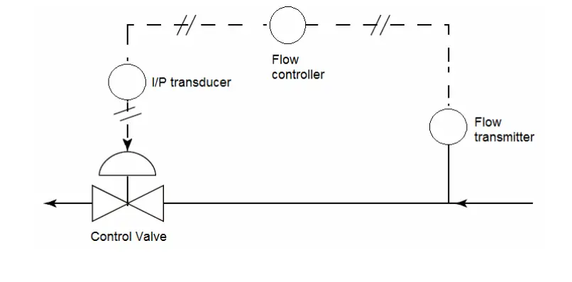
A control valve receives the information from various sensors and transmitters in a control loop and processes that data to manage the control of the fluid parameter. The following figure shows a typical control loop for a control valve
Typical Control Loop of a Control Valve
Components of Control Valve
Control valves have basically three interactive components:
a valve body subassembly (either with a reciprocating or rotating stem),
an actuating device (usually a spring diaphragm type),
a valve positioner (an instrument that converts an electronic control signal from a controller, or computer, into an air signal to control the position of the control valve stem), and
an air set or regulator to supply air pressure to the positioner.
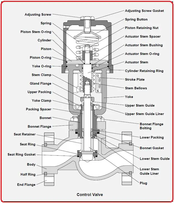
Parts of a Typical Control Valve
Control Valve Features
The most common valve body style used as a control valve is the globe valve. Although many other body styles such as angle valves, Three-way valves, Eccentric rotary plug valves, semispherical ball valves, Ball Valves, Butterfly valves, etc are used, the globe valve provides the most effective means to regulate and control flow.
Control valves use signals received from instruments positioned throughout the piping system to automatically make adjustments that regulate the commodity within the pipe. Though control valves can perform many functions, they are typically used to control the flow of a commodity within a pipe or to limit its pressure.
Control valves must be arranged within a run of the pipe so that they can be easily operated. To achieve this, control valve manifolds are configured. Control valve manifolds make control valves readily accessible to plant workers.
Control Valve Actuators
The actuator of a control valve is the assembly that provides power for moving the control valve mechanisms. In a control valve loop, actuators move the plug, ball, or vane upon receipt of a signal from the control system to allow or disallow full or partial flow. There are three types of actuators in a Control Valve. They are
Pneumatic Actuators
Electric Actuators and
Hydraulic Actuators
Pneumatic Actuators:
Pneumatic Actuators are the most basic and widely used control valve actuators that use an air or gas signal from an external source to produce a modulating control action. The top port sends the pneumatic signal to the actuator that exerts pressure on the diaphragm plate to move the valve stem. On loss of driver power, pneumatic actuators provide a fail-safe response.
Electric Actuators:
Electric Actuators of a control valve are motor-driven devices. A motor rotates when an electrical signal is received. A gear reduction drive converts this rotating motion into a linear motion to drive the control valve stem for flow modulation. They are used for On-OFF applications in isolation services and for continuous positioning control.
Hydraulic Actuators:
Control Valve Hydraulic actuators use hydraulic oil as the signal fluid. When the force required to move the valve stem is high, hydraulic actuators are used. Due to the non-compressibility of the liquid they exhibit stable positioning.
Specifying Control Valve
The first step in specifying a control valve is to define its function in the given application. In some, it will operate as an on-off valve that opens or closes following the commands of a programmable controller on, say, a batch process. In others, it will be used to remotely set a flow rate in a process—that is, it will be used as a manually controlled variable orifice in a pipe (an open-loop application).
Finally, in more sophisticated applications, the control valve will serve as the final control element in a process control loop and respond to the sometimes infinitely small variations of a signal coming from a controller (typically a computer). The signal will be generated in response to a deviation in the desired temperature, pressure, or level of a process fluid as measured by a transmitter.
More than 90 percent of all control valves use pneumatic actuating devices—either spring-opposed diaphragm types or piston-actuated.
Materials for Control Valves
For noncorrosive use, the material of choice is carbon steel (ASTM A216 Grade WCB, if cast; and A105 when forged). For mild, corrosive applications, valve housings are made from type CF8M (316 stainless steel). However, Teflon-lined housings and exotic alloys, such as Hastelloy, Monel, or Titanium are available for highly corrosive fluids.
Characteristics of different valves to serve as Control Valve
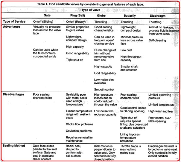
Control Valves play a major role in the everyday effort to increase process plant profitability and conserve energy. Proper selection of these valves can have a significant financial impact on the overall cost of a project and how well the process can be controlled. To narrow down the choices, the engineer must understand how the general characteristics of each type of valve match up with the design requirements. Refer to table 1 for the general characteristics of a few valve types.
General Features of Each type of Valve
Control Valve Characteristics
Each control valve has a flow characteristic, which describes the relationship between the flow rate and the control valve travel. As a valve opens, the flow characteristic, which is inherent to the design of the selected valve, allows a certain amount of flow through the valve at a particular percentage of the stroke. This enables flow regulation through the control valve in a predictable manner. The three most common types of control valve flow characteristics are:
Linear
Equal percentage
Quick opening
Control Valve Selection
There are two major parameters on which the control valve selection is dependent-
Service condition and
Load characteristics
Other parameters that determine the control valve selection are
Ability to control the flow rate;
Lack of turbulence or resistance to flow when fully open – turbulence reduces head pressure;
Quick opening and closing mechanism – rapid response is many times needed in an emergency or for safety;
Tight shut-off – prevents leaks against high pressure;
Ability to allow flow in one direction only – prevents return;
Opening at a pre-set pressure – procedure control to prevent equipment damage; and
Ability to handle abrasive fluids – hardened material prevents rapid wear.
Control Valve Types
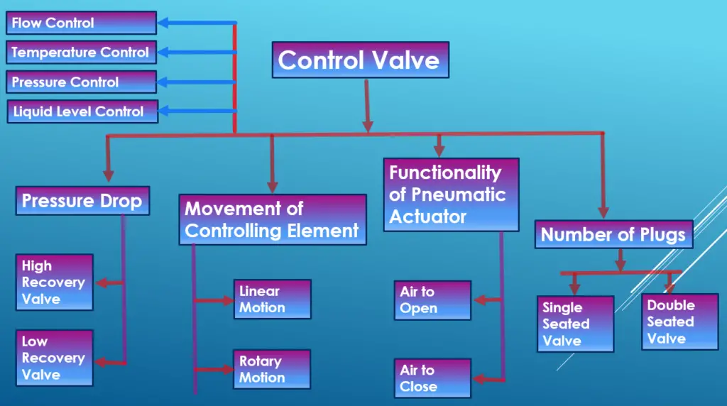
Depending on various parameters control valves are classified as follows:
Types of control Valve
Pressure Control Valve
Pressure Control valves help in controlling system pressure within a limit. They are installed in all systems where pressure fluctuations can occur and can cause a hazard if not controlled. Pressure control valves are basically closed valves with a restriction for pressure control. There are two mechanisms on which pressure control valves operate:
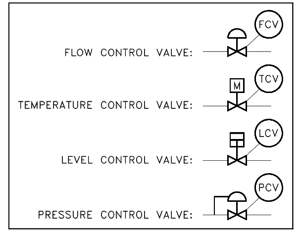
The symbols used for different types of control valves in P&ID are as given below:
Control Valve Symbols in P&ID
How to install a Control Valve?
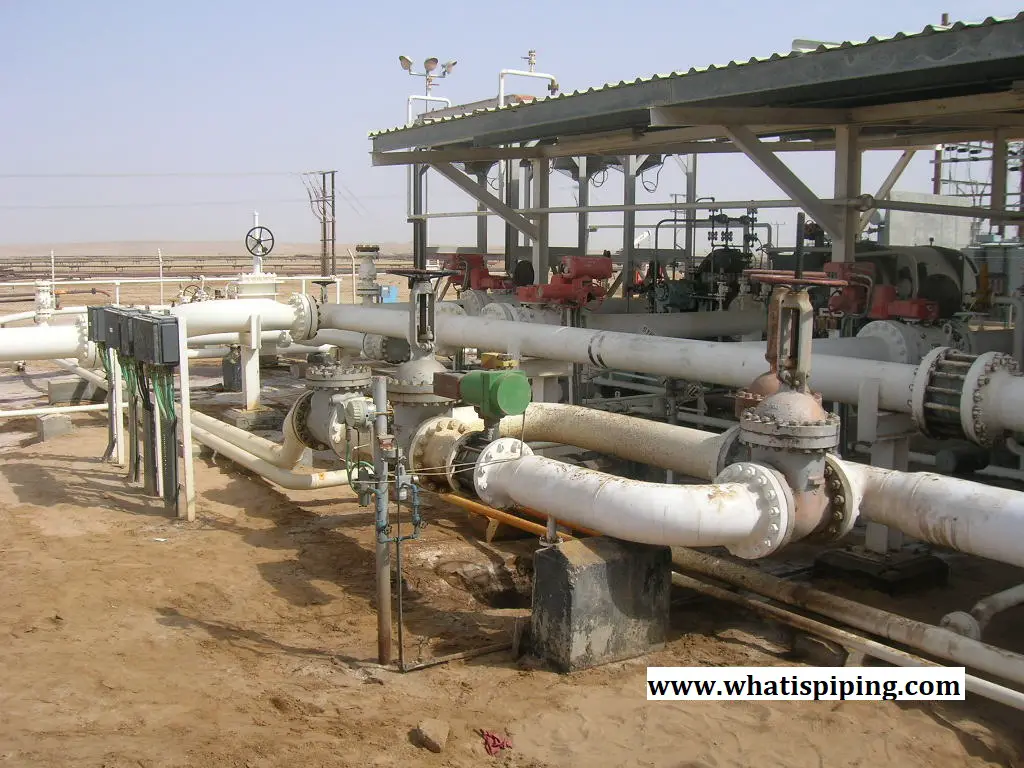
Control valves are normally installed in a horizontal orientation in a straight pipe run preferably away from elbows. The actuator is kept in a vertical position. A bypass valve is installed for continuous operation during control valve inspection and maintenance. Upstream and downstream isolation valves and drains are added to the piping system to isolate the control valve for maintenance. The following figure shows a typical control valve installed in a piping system.
The sealing quality of a metal seated control valve is very important. Normally, The higher the pressure class of the valve, the lower the allowable leakage rate in a closed position.
Control Valve Assembly
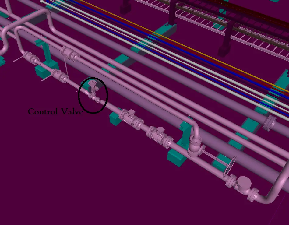
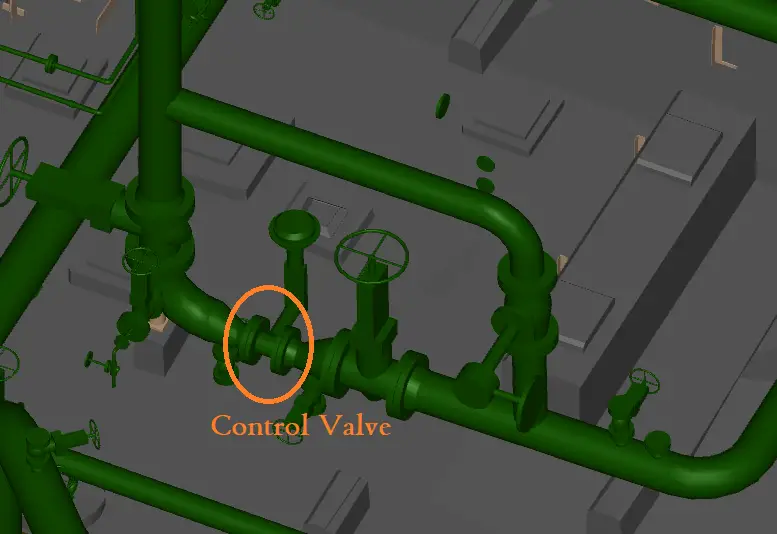
The control valve assembly is used for controlling process parameters in piping systems. The following figures show typical different arrangements of control valve assemblies
Control Valve Assembly Arrangement
Various types of control Valve Assembly Arrangements
Example of Control Valve Assembly
The following videos will explain more details about control valves and their working methodology:
Control Valve Basics
The following video briefly describes the basics of Industrial Control Valves.
Flow control valves
Flow control valves are devices that manage the rate of fluid flow in part of a hydraulic circuit. The following video tutorial explains the basics of flow control valves
A Material Take Off (MTO) is a process to study a drawing and find out all the materials required to construct the drawing in physical form. In each individual drawing, specific items are listed along with approximate quantities. Those materials are then tabulated in excel or in other company-specific standard forms as per size and quantity involved to make a comprehensive material listing which is sent to the procurement department for purchasing or to the construction team for fabrication. Material Take Off or MTO is a very important step in materials management for procurement and construction.
Depending on the project size and complexity, the materials list or material take-off can be long or short. Without proper management of these materials, unnecessary delay and expense in project execution can happen.
Major Steps in Piping Material Management
The major steps involved in Piping Material Management are:
Material Take Off (MTO) of piping items or piping material take-off is a detailed listing of piping components required for a given project. It includes:
Commodity Code,
Size,
Quantity and
Purchase description for all the items.
Purpose of Material Take Off
The Material Take Off or MTO is used for the purpose of
Making Proposal,
Material Estimation &
Preparation of Purchase Requisitions.
Material Take Off helps in a rough estimation of the project cost
Initial MTO (also called First MTO) is generated manually at the beginning of the project. Very often, the 3-D model is not available or complete at that stage. Hence, Initial Material Take Off is generated on the basis of P&ID and Project Specifications.
This is required as the complete modeling takes time and we need the MTO at the earliest to initiate procurement activities.
As the 3D modeling progresses, detailed MTO is generated electronically by the 3D modeling software (PDS/PDMS, etc). The Piping Material Specification is generated in electronic format and is linked to the 3-D modeling software for the purpose.
Accuracy and correctness are of prime importance and digital material take-off provides more accurate estimation in less time with respect to manual MTO estimation.
Following input, documents are required for working out the initial (First) MTO.
Piping & Instrumentation Diagram (P&ID)
Line List
Standard/Project PMS.
Project specification & standard drawings.
Equipment Drawings/Data Sheet.
Instrument Hook-up Sketches.
Manual Material Take-Off Preparation
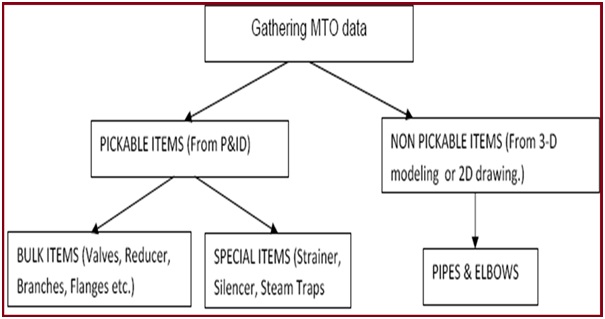
Fig. 1 below shows a flow diagram of how manual material take-off is generated. It is a time taking process and must be thoroughly checked as manual estimation is prone to errors.
Fig. 1: Flow Diagram for Manual MTO Generation.
Steps for Manual MTO Preparation
Manual Material Take Off is generated in the following steps:
Make a folder of all P&IDs as a master copy for 1st Bulk MTO.
All pick-able items are entered in an MTO format excel File, refer next sheet.
All entries must be taken against a specific line number. In case a line number is not marked on P&ID, it has to be assumed by adding suffixes A, B, etc. with the main header line.
Queries shall be raised for components that are not available in PMS. All such queries shall be documented & MTO shall be updated as & when queries are resolved.
All assumptions made are documented & such items shall be marked as Hold. All assumed data is maintained in a separate file & tracked. MTO shall be updated whenever confirmed data is received.
The basis of Material Take Off is a properly issued version of P & ID or documented communication.
Prepare a datasheet having all Piping / Material data of special items.
Send datasheet to process & related department for review & incorporating missing data & comments. All the missing data/information required to be filled by other disciplines shall be highlighted by the material team.
Prepare IFP datasheet, when commented & updated datasheet is received.
Non Pickable Items
Pipe Length & Elbows quantity is generated by 3-D modeling.
Generation of Total MTO
Combine pick-able bulk items and non-pickable items (except piping special items)
Combined data is processed and validated against the piping material specification (PMS).
Check & Rectify errors.
The final BOM (Bill Of Material) is received from the successful run file.
Piping specials are processed separately
Preparation of Material Requisition
Material requisition for purchase includes:
Bill of materials having commodity codes, sizes, material specifications, and quantity
Additional technical requirements, inspection & test guidelines, documentation requirements, and guidelines for bid submission
Receipt of quotations from prospective bidders and Technical Bid Evaluation
Vendor offers are invited for the material requisition
Received offers are evaluated to ensure technical compliance to material and project specifications
TBE report is sent to the procurement department
The purchase order is placed on a technically acceptable vendor after commercial negotiations
Vendor document review/approval
After the purchase order is placed on a particular vendor, the vendor submits all the documents required per material requisition.
These documents are reviewed and commented on to ensure compliance with all the specifications
After the approval of the documents, the actual manufacturing of the material begins.
Inspection and testing of materials are carried out at the vendor shop according to approved ITP/QAP
Material is dispatched to the site after successful inspection and quality checks.
Normally every organization has its own standard format for each of the below-mentioned Material Take Off categories:
Isolation joints provide an electrical break between pipeline sections of the same or different pipelines, or between pipeline sections and neighboring structures. This limits the possibility of electrical bridging across the joint. The Purpose of the isolation joint is to prevent detrimental electro-chemical interaction and improve the effectiveness of the cathodic protection system. Isolating joints are also used to ensure effective current distribution for a cathodic protection system. They are also known as Isolating Joints or Insulating Joints.
A monolithic isolation joint (MIJ) is a single-piece electrical isolation block that is widely used in pipeline systems to reduce corrosion by the methods of cathodic protection. Monolithic isolation joints are an integral part of the pipeline system and provide satisfactory long-term integrity. All the components of the MIJ system are fully encased in forged steel bodies.
Isolating Joint Functional Requirements
The isolation joint shall be suitable for Pigging Operation.
Slip-on Flanges shall not be used.
The isolation joints shall be able to withstand the operating conditions stated in the requisition sheets. Where the operating conditions are not stated, the following operating conditions shall apply.
Installation: Above-ground. Pipeline isolation joints are installed in the aboveground part immediately after the aboveground-belowground transition.
Design temperature: 82 deg C maximum & 5 deg minimum
Advantages of Monolithic Isolation Joints
For buried pipeline applications, monolithic isolation joints are more common. External attacks from extreme environments and tampering are prevented by the robust steel body. In general, MIJs are installed aboveground in pipeline systems in order to limit the possibility of electrical bridging across the joint. It is intended to be girth welded between two pipeline sections. The benefits that a monolithic isolation joint serves are:
MIJs eliminate the source of a short circuit by removing bolts, sleeves, and washers.
As there are no flanges, gaskets, nuts, washers, sleeves, or bolts, the requirement for field assembly is eliminated. At the same time, the chances of leakage due to improper field assembly are also removed.
MIJ system is usually less expensive as compared to insulated gasket flange assembly.
Isolation Joint Components
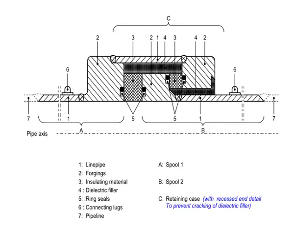
The isolation joint shall consist of the following components
1) Two spools, each consisting of a pipe segment with a beveled end for welding to the pipeline on one side, having a welded-on boltless flange at the other end for encapsulation into isolating and filler material.
The material used for the pipe segments shall be compatible with the pipeline material.
2) A rigid casting (retaining ring) for strength connection.
One set of ring seals for pipeline internal pressure containment below 50 bar (g).
A double sealing arrangement shall be specified for design pressure in excess of 50 bar (g).
3) Two terminal connecting lugs on the outer surface of each spool. Each lug shall be suitable for an M10 bolted cable connection.
Dimensional Requirements of Isolation Joint
The Internal Diameter of the Isolating Joint shall not deviate by more than +/- 2% of the nominal internal diameter of the pipeline for diameters not exceeding DN500 and +/-1.5% for nominal diameters above DN500.
Monolithic Isolation joints are designed to match the metallurgy and application demands of the pipeline following the specifications of the project to ensure long maintenance-free service life.
Note that, isolation joints are the weakest elements in the pipeline system and therefore, the force and moment transfer to the joint must be limited. The force and moments at the pipeline isolating joint have to be qualified against vendor-given allowable values while performing stress analysis of the specific pipeline system. The design of isolation joints can be based on Shell DEP 31.40.21.31
Hydrostatic Test in Piping: Hydrotest Vs Pneumatic Test
A hydrostatic test or hydro test is a widely used method to ensure leak tightness and safety of pressure vessels, piping systems, pipeline systems, plumbing systems, tanks, boilers, cylinders, and other system components. The test is performed by subjecting the material to a predecided controlled pressure known as test pressure and then checking the material response under pressure. It is a type of pressure testing performed before commissioning. In this article, we will learn about the hydrostatic testing procedure of piping systems in detail.
Part A: Pressure Test (Leak Test) in Piping
What is a Pressure Test in Piping?
A pressure test of pipes is always required for a new pressure piping system before use or an existing pressurized system after repair or alteration to ensure the following:
Safety
Reliability of operation
and leak tightness of pressure systems
Also, the last physical quality test in the fabrication process
Subsequent to repairs and heat treatment and prior to the initial operation or commissioning of any plant it has to be ensured that there is no evidence of leakage by Pressure Testing. As the main aim of performing pressure testing in piping systems is to ensure leak tightness, it is also known as the leak test of piping.
When to Perform a Pressure Test/Leak Test in Piping?
As per the governing code, a pressure test has to be performed on the piping system after all hot works have been completed on a certain piping system. Here the term hot work means everything related to welding or post-weld heat treatment (PWHT). PWHT also has the potential of degrading the mechanical properties of piping, in case not addressed properly. And this is the reason why the code calls for NDT after the PWHT operation.
In case after carrying out pressure testing, some modification has to be made requiring hot work, which calls for a retest as per code. Here code specifies that the minor repairs/modifications may be waived off provided adequate measures have been taken to ensure sound construction. Now this decision as to which repairs or modifications may be waived off should be taken very carefully. Normally, the maximum extent of repairs not requiring retesting shall be the tack welding of any piping support or pad. Anything else shall be done following a retest.
Pressure testing and conducting 100% radiography or ultrasonic inspection shall not be interchanged. In case carrying out of hydrostatic or pneumatic test stands impractical then 100% radiography or ultrasonic testing may be performed but in addition to this, it is advisable to check that the whole piping and its components have been supplied against acceptable ASTM standards and required test certificates are available.
Conducting 100% radiography of all the weld joints assure that your weld joints are defect-free but can never provide you with the assurance of mechanical integrity of a system.
This is also to be noted that radiography / ultrasonic inspection shall also not be waived off if the pipeline is to be hydrostatically tested. This may pose an additional safety risk during the test. Moreover, some defects in the weld zones may prove to be detrimental way after being taken in service due to severe extended service conditions.
Pressure tests (both hydrostatic and pneumatic) must always be performed under controlled conditions, following an approved test plan, and documented in a test record. A single approved test plan could be used for several similar tests, but for each test, a separate test record is required.
The Basis for Pressure Test Method Selection
Normally the following basis is followed in the process piping industry for the selection of hydro or pneumatic tests in piping.
If the fluid handled by the piping system is liquid then the pipe must be hydro-tested.
If the fluid handled is vapor or gas then the internal design pressure dictates the testing method. For pipe design pressure 10 bar and above the pipe is hydro-tested. For pipe design pressure below 10 bar pipe is pneumatically tested.
If the fluid handled is steam then hydro testing is suggested.
If the fluid handled is a two-phase flow then hydro testing is suggested. However, for big-size flare headers, pneumatic testing is performed.
If hydrostatic testing has the potential to damage the internal lining or insulation, then pneumatic testing is suggested.
When the water (moisture) used in the hydro test has the potential to contaminate the process, a pneumatic test may be opted for.
If the Piping is not designed for Hydrostatic pressure test conditions, then the pneumatic test is performed.
Instrument-air lines are pneumatically tested.
Part B: Hydrostatic Test or Hydrotest in Piping
What is a Hydrotest or Hydrostatic Test?
Hydro test or Hydrostatic test is a type of pressure test performed on piping, pressure vessels, and other pressurized systems to check system integrity under pressure conditions. A hydrostatic test is performed by using water as the test medium.
How to Calculate Hydrotest Pressure in Piping? | Piping Hydrostatic Test Pressure Calculation
ASME Code B 31.3 provides the basis for test pressure. The minimum hydrostatic test pressure for metallic piping shall be as per the following equation:
Pt=1.5*Pd*(St/Sd)
Here, Pt=the minimum test gauge pressure Pd=internal design gauge pressure St=allowable stress value at the test temperature Sd=allowable stress value at design temperature. The maximum allowable value of St/Sd is 6.5
Note that, ASME B31.3 provides a provision to reduce the hydrostatic test pressure in piping under certain conditions. Quoting the Process Piping code ASME B31.3 the rules for reduced test pressure are:
“If the test pressure would produce a circumferential or longitudinal stress (based on minimum pipe wall thickness) in excess of yield strength at test temperature or is greater than 1.5 times the component rating at test temperature, the test pressure may be reduced to the maximum pressure that will not exceed the lesser of the yield strength or 1.5 times a component rating at test temperature.
However, the hydrostatic test pressure must not be less than the design pressure.“
Hydrostatic Test Duration
Normally every EPC company has its own standard for the duration of tests. However, the recommended practice is that a QC inspector has to walk through the whole piping system and check for leaks. Every single length of piping, welds, and bolted connections shall be visually examined for any leakage. The duration of this activity varies with the span of the piping system. For a larger piping system time taken for this activity is enough to clear the pressure test. In the case of a piping system having a smaller span, 1 hour time may be made as standard practice for hydrostatic testing. For the Pneumatic test, the test time is far less.
As per ASME B31.3, The leak test pressure has to be maintained for at least 10 min and then all joints and connections shall be examined for leaks.
Procedure for Hydrostatic Testing
The following are the basic steps involved in the hydrostatic testing of piping systems:
Preparation: Before testing can begin, the system must be cleaned and dried to remove any debris or moisture that could interfere with the test. All valves, flanges, and fittings must be properly secured and tightened to prevent leaks during the test.
Filling: Once the system is prepared, it is filled with water or another suitable test fluid. The fluid is usually pumped into the system until it is completely filled and all air is purged from the lines.
Pressurization: After the system is filled, it is pressurized slowly and gradually to the required test pressure. The pressure is usually increased in increments to allow for any leaks or weaknesses to be detected before reaching the full test pressure.
Stabilization: Once the system has been pressurized to the required test pressure, it is held at that pressure for a specified period of time to allow for any leaks to be detected. The duration of the test may vary depending on the type and size of the system being tested.
Inspection: While the system is pressurized, it is inspected for leaks or other defects using a combination of visual, audible, and/or electronic methods. Any leaks or defects that are detected must be repaired before the system can be considered safe for use.
Depressurization: After the test is completed, the system is slowly depressurized to prevent sudden changes in pressure that could damage the system. The test fluid is then drained from the system and properly disposed of.
Documentation: Finally, a detailed report of the test results is prepared, including the pressure and duration of the test, any defects or leaks that were detected, and any repairs that were made. This documentation is important for maintaining records of the system’s safety and compliance with regulatory requirements.
Hydrotest Fluid
As the name signifies, the test has to be performed using clean potable water free from suspended solids. However different codes specify different requirements for water quality. Hence, hydro tests need to be performed following those instructions.
Hydrotest System Preparation
The piping network and the connected equipment must be prepared thoroughly before proceeding with pressure tests like hydro or pneumatic testing. Codes like ASME B31.3/ ASME B 31.1 and local company instructions normally provide guidelines for such preparation.
Piping systems that are normally open to the atmosphere, such as drains, vents, discharge piping from pressure-relieving devices, sewers, and stack downstream of the seal drum, need not be subjected to the piping test pressure.
For some
countries, The provincial local inspector shall be notified at least 48 hours
in advance of pressure testing of piping under the jurisdiction of the
provincial safety code for witnessing at his/her option.
The following equipment shall be excluded from all piping pressure tests:
Vessels and tanks
Heat exchangers
Rotating machinery, such as pumps, compressors, and turbines
Equipment and Supplier furnished piping specifically recommended by the manufacturer not to be tested
Underground
portions of piping systems may be tested and covered before testing aboveground
portions.
Roughly, The
following steps should be followed for preparing the piping system for leakage
testing.
Comparison of P&ID/PEFS and Isometric Drawing
The first step is to compare the piping isometrics with the P&ID drawings to check if any discrepancy exists. All valve types, flow directions, branch tie-ins, and any material changes, etc are reviewed thoroughly. In-line components are verified and ensured that they are able to withstand the test pressure.
Thorough Inspection before testing
All sorts of ultrasonic and radiographic inspections or checks must be carried out before the actual pressure test is started. Conducting 100% radiography of all the weld joints assures that your weld joints are defect-free but can never provide you with the assurance of the mechanical integrity of a system. This is also to be noted that radiography / ultrasonic inspection shall also not be waived off if the pipeline is to be hydrostatically tested.
Joints shall be exposed
All joints, welds (including structural attachment welds to pressure-containing components), and bonds shall be left uninsulated and exposed for examination during leak testing as per Section 345.3.1 of ASME B31.3, except that joints previously tested in accordance with this Code may be insulated or covered.
Provision of Temporary Supports
If required Pipings designed for vapor or gas services shall be provided with additional temporary supports, to support the weight of the test liquid as the test liquid is heavier than the service fluid.
Spring Supports in Piping System
All Spring supports shall be kept in locked condition during hydrostatic testing. Holding pins shall not be removed from spring supports until testing is completed and the system is drained. Care shall be taken to avoid overloading any parts of the supporting structures during hydrostatic testing.
Instruments
All in-line Instruments shall be either removed or blocked prior to hydro testing to prevent damage during hydro testing (e.g. meters).
Instrument take-off piping and sampling system piping, up to the first block valve, shall be tested with the piping to which it is connected.
Instrument lead lines, between the first block valve and the instruments to which they are connected, shall be pressure tested to the test pressure of the associated piping. Testing may be performed separately or at the same time as the piping is tested, but the instruments shall be disconnected.
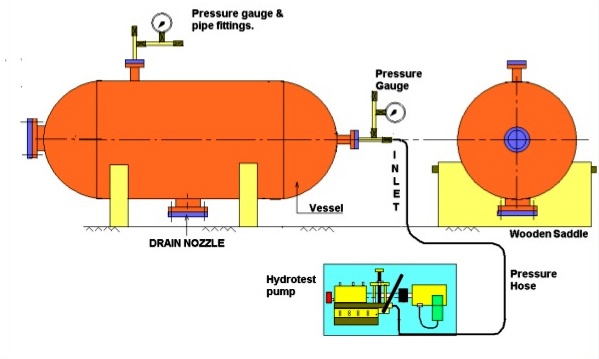
A sample figure showing the hydro-testing scheme
Hydro test for Piping with Expansion Joints
If there is an expansion joint in the piping system under the leakage test, the following criteria shall be applied.
An expansion joint that depends on external main anchors to restrain pressure end load shall be tested in place in the piping system.
A self-restrained expansion joint previously shop-tested by the manufacturer
A piping system containing expansion joints shall be leak tested without temporary joint or anchor restraint at the lesser of
150 % of design pressure for a bellows-type expansion joint, or
the system test pressure is determined in accordance with para. 345
In no case shall a bellows-type expansion joint be subjected to a test pressure greater than the manufacturer’s test pressure.
When a system leak test at a pressure greater than the minimum test pressure specified in (c), or greater than 150% of the design pressure within the limitations of para. 345.2.1(a) is required, bellows-type expansion joints shall be removed from the piping system, or temporary restraints shall be added to limit main anchor loads if necessary.
Limits of Tested Piping
Equipment that is not to be tested must be either disconnected from the piping or isolated by blinds or other means during the test. A valve may be used provided the valve is suitable for the test pressure.
Rotating Machinery
Rotary machinery, such as pumps, compressors, or steam turbines, have lube and seal oil systems that could be impaired by the presence of water. These systems shall not be subjected to the piping test pressure.
Test Water
Clean water that will not corrode and/or damage the test system shall be used for hydrostatic tests. If municipal water is not available, supply water may be obtained from a native water supply. Water containing silt or suspended material shall not be used, and a suitable filter with 40 mesh should be provided in the filling line. A mixture of glycol-water shall be used where the ambient temperature may reach less than 0°C (32°F) during testing or prior to dry-out
Temporary Spades and Blanks
If Temporary spades and blanks are installed for testing purposes, those must be designed to withstand the test pressure without distortion. The presence of spades shall be clearly visible during testing. The recommended practice is to use standard blind flanges as per ASME B16.5 or B16.47 and spades acc. to ASME B16.48.
Check Valves
Check Valves shall have the piston or flap removed for testing, where pressure can not be located on the upstream side of the valve. The locking device of the flap pivot pin shall be reinstated together with the flap and a new cover gasket shall be installed after the completion of the test.
Completion of Hot Work
Wherever applicable All hot works, related to welding or the post-weld heat treatment have to be completed before the Hydrostatic test.
Installation of Barriers
It is necessary to install safety barriers around the piping system under test prior to starting pressurization related to testing. Public Address announcements and access restriction procedures such as permits to work shall be implemented. Under no circumstances should anyone other than an authorized person be allowed within the safety barriers.
Prior to the leakage test, Control Valves and soft-seal block Valves shall be removed from the piping and replaced with pipe spools. However, All welded Valves need to be tested along with pipings otherwise Radiographic Testing of golden joints (welded) will be required.
Physical Inspection
Prior to the pressure test following should be checked :
Vents or other high point connections shall be opened to eliminate air from and plugged during the test.
lines that are to receive a hydrostatic test.
Completed and torqued flanges with no missing bolts or gaskets.
Proper material type is verified using color codes or markings, and heat numbers are recorded if required by the codes.
Correct valve type and orientation.
Vents and drains were installed to allow proper filling and draining
When a pressure test is required to be maintained for a period of time during which the testing medium in the system would be subject to thermal expansion, the provision shall be made for the relief of any pressure greater than the maximum test pressure.
All required piping stress relief, weld examinations, and welding documentation are completed and acceptable. A relief valve is to be added such that the test pressure is not exceeded beyond a safe amount.
When conducting tests at freezing temperatures, the test shall not take more than 4 hours, and special precautions, such as using a glycol/water mixture, shall be observed to avoid freezing damage
Some important points to consider while hydro-testing of piping:
The tower overhead lines which are normally hydro-tested shall be decided by the pipe stress engineer whether to hydro-test after erection or at grade, based on the capacity of the standard clip available as per engineering specification for pipe supports.
During the hydro test in the case of big-bore, it should be decided first that the line is to be hydro tested on rack or grade if the hydro test is done on the rack, the hydro test load should be considered in case of vapor lines while providing structure/rack loading information.
Hydrotesting Documentation
The individual system documentation i.e. test pack shall be available prior to any testing and shall include information such as test limits, test pressure, test medium, duration, test blinds, blind flanges, vents, and drains.
The use of marked-up P&IDs coupled with isolation registers should be utilized to identify the locations of blinds, Valves, vents, and drains.
Records shall be
made of each piping system test. In general, these records shall include the
following information:
Date of test
Identification of piping system
Test medium
Test pressure
Minimum ambient temperature
Test medium temperature
Certification by examiner
Test duration
Pipe standards or
specifications for the test
Pressure and temperature
recording charts and logs
Location and cause of
leaks/failures
Repair procedures used in the event that the pipe leaked or failed
Test results
Name of the test operator
Minimum metal temperature (if
applicable)
Test gauge calibration date
Forms, when
completed, shall be retained in the Construction Contractor’s QC file as a
permanent record.
Hydrostatic Testing Equipment
Testing equipment such as pumps, manifolds, pressure, and temperature recorders, and pressure gauges should be within calibration/certification (as per company procedures) and connected to the lowest convenient connection within the system to ensure the best results.
Hydrostatic Testing Problems
Even though proper industry-approved methods are followed for pressure testing, still due to some negligence hazards do happen. Some of the most common reasons for failures during hydro tests and pneumatic tests are:
Over pressurization
Operator error
Inadequate equipment
Poor component design
Improper isolation of the tested system from equipment or remaining parts of the system.
Inadequate repairs
So it is always a good idea to follow safe work practices for Hydro testing. The below-mentioned steps can be followed to avoid hazards of Pressure Testing:
Prepare a standard operating procedure (SOP) for the hydro test or pneumatic test following the latest applicable code
Developing a checklist using the sop and sticking to it.
Train the involved personnel indicating the potential hazards and safety measures.
Develop a Pre-test safety plan and conduct a pre-test safety briefing just prior to hydro testing.
Perform a Walk-down inspection following the checklist to ensure all hydro test checkpoints are taken care of.
After the hydrostatic test, gradually release the pressure and drain the system.
Difficulties with Hydrostatic Testing
Supply & disposal of water, disposal of fluid additives
A water leak can cause equipment damage
Freeze susceptibility
Structural support limitations
Contamination
Operational impacts – process contaminant
Affect dry-out of internal refractory linings
Piping Hydrotest Checklist | Hydrostatic Test Checklist
The following section provides a sample of the hydro test checklist to inform the major points that must be considered.
Hydrotesting Checklist
Pre HydroTest Checklist
Sr No
Description
Complied
Not Complied
Remarks
1
All Affected people like the Owner, Managers, Workers, and Suppliers, informed
2
Test pressure and duration received or estimated
3
Standard Operating Procedure identified
4
The Pre-test safety plan completed
5
Required workers properly trained
6
Test Equipment inspected, calibrated, and certified
7
Test Temperature verified
8
Test area barricaded and warning signs posted to keep non-essential members outside the hydro-test zone
9
A walk-down inspection performed
10
Hydrotest system preparation proper
11
Vent Valve, Block Valve closed
12
All joints are exposed, No insulation
13
System parts are properly aligned
14
Torque on bolted connections as per manufacturer guidelines
15
Lockout tag-out finished as per guidelines
16
Emergency contact information collected
17
proper isolation from equipment and non-test parts following SOP performed
Pressure is applied gradually following work procedure/standards
22
Pressure maintained for the pre-decided time duration
23
All exposed joints are thoroughly checked for leakage potential.
Post-Hydrotest Checklist
24
Repairs started after the release of Hydrotest Pressure.
25
Pressure is released gradually.
26
Water was disposed of as per the procedure
27
Repairs performed following procedures
Table 1: Hydrotest Checklist
Hydrostatic Testing Cost
The cost for hydrostatic testing of piping systems can vary widely depending on a variety of factors, such as the size and complexity of the system, the type of test fluid used, and the location of the system. Other factors that can affect the cost include the need for special equipment, such as pumps and gauges, and the cost of any necessary repairs or maintenance.
In general, the cost of hydrostatic testing can range from a few hundred dollars to several thousand dollars or more. For small, simple systems, the cost may be relatively low, while larger, more complex systems can require more time, labor, and equipment, resulting in higher costs.
To get an accurate estimate of the cost of hydrostatic testing of a specific piping system, it is best to contact a qualified testing contractor or service provider and request a quote based on the specific details of the system in question.
Difference between Hydro Test and Hydrostatic Test
Hydrotest and hydrostatic tests are often used interchangeably to refer to the same testing process, which involves filling a piping system or component with a fluid, usually water, and subjecting it to pressure to check for leaks or weaknesses.
Part C: Pneumatic Test in Piping
What is the Pneumatic Test?
The pneumatic test is a type of pressure test for checking system integrity under pressurized conditions and is applied to systems where the hydrostatic test is difficult to apply. A pneumatic test uses clean, dry, and oil-free air, nitrogen, or any non-flammable and non-toxic gas.
How to Calculate Pneumatic Test Pressure? | Pneumatic Test Pressure
The pneumatic test pressure shall be as per the following equation:
Pt=1.1*Pd
Piping Pneumatic Testing Procedure
Pneumatic test for piping is done in three steps: Pressurization, Inspection, and De-pressurization.
To avoid brittle fracture, the pressure shall be increased by less than 10% of test pressure per minute into the system allowing adequate time for temperature equalization. The pressurization shall follow this sequence:
Step 1. Gradually increase to 1.5 barg
Step 2. Hold for 10 minutes;
Step 3. Perform a preliminary check, including examination of joints by applying soap methods.
Step 4. If leaks are discovered, release pressure, repair, and return
Step 5. Gradually increase the pressure in steps of 10% until the test pressure is reached, holding the pressure at each step for sufficient time (minimum 10 minutes) to allow the temperature and strain to stabilize; Observe the pressure gauge for loss of system pressure at every incremental step stage. If pressure loss exceeds 10% of test pressure, the system pressure should be reduced to 1.5 barg and follow steps 3 & step 4.
Step 6. Hold for 10 minutes at 100% test pressure and Observe the pressure gauge for loss
Step 7. Depressurization of the system.
The depressurization rate shall be calculated, considering the Joule-Thomson effect, to prevent brittle fracture while the system remains under stress.
Inspection shall only be permitted after the pneumatic test pressure has been achieved, held, and then reduced to the design pressure
Difficulties with Pneumatic Testing
Pneumatic tests are potentially more dangerous than hydrostatic tests because of the higher level of potential energy stored during compressing of the gas. Care must be exercised to minimize the chance of brittle failure during testing by initially assuring the system is suitable for pneumatic testing.
Pneumatic tests could be performed only when at least one of the following conditions exists:
When the systems are designed in such a way that they cannot be filled with water.
When the systems are such that it is to be used in services where traces of the testing medium cannot be tolerated.
Using a pneumatic test instead of hydrostatic requires approval from proper authority or body.
Part D: Difference between Hydrostatic Test and Pneumatic Test
Comparison of Hydrostatic Testing and Pneumatic Testing
The following table lists the major differences between hydrostatic and pneumatic testing.
Hydrostatic Testing
Pneumatic Testing
Hydrostatic test pressure is normally 50% higher (As per ASME B31.3) than the design pressure.
Pneumatic test pressure is normally 10% higher than the design pressure
Hydrotest is recommended for high-pressure applications.
A Pneumatic test is recommended only for low-pressure applications.
In a hydro test, the test media (Water) used is not compressible by pressure application.
In a pneumatic test, the test media, Air is compressible by pressure application.
In hydrostatic testing, the energy stored per unit volume of water under test pressure is negligible.
The energy stored per unit volume of compressed air under test pressure in the case of a pneumatic test is very high.
Needs thorough cleaning after the hydrostatic test to eliminate moisture, especially for services that are reactive to moisture/fluids.
Easy to clean after pneumatic testing.
Pressure Relief devices are usually recommended to control a sudden increase in pressure during hydro testing.
Pressure relief devices are a must during the pneumatic test to ensure no over-pressurization.
Chances of equipment/ Pipe/test apparatus failures are very low during hydro testing.
Chances of equipment/ Pipe/test apparatus failures are high during pneumatic testing.
The weight of equipment along with the hydro test medium as water is high hence special attention should be given to the floor and supporting arrangements.
The weight of equipment with the pneumatic test medium as air is comparatively less.
Needs verification and examination of joints and connections before testing.
Needs very careful checking of weld joints thoroughly before testing.
In hydrostatic testing, the test media can be reused or transferred to other places after testing.
In pneumatic testing, the test media can not be reused or transferred to other places after testing.
Skilled and semi-skilled personnel can carry out the test.
Needs the involvement of senior experienced staff to monitor the test.
Recommended that large volumes are to be tested at the same time (for example pipelines).
If pipelines are tested should be done with small segmental lengths at a time.
Damages made by failures are less compared to failures in pneumatic testing.
Damages made by failures in testing are very huge and extensive as compared to hydrostatic testing.
Hydrotest is a regular day-to-day practice and safe procedure and it can be followed in any work site.
Needs special attention and safety precautions for performing a pneumatic test.
Pressure changes finite amounts by an infinitesimal change in volume.
The pressure change is proportional to the volume change.
Table 2: Hydro Test vs Pneumatic Test
Frequently Asked Questions | Hydrotest FAQs
What is the difference between the Hydro test and the Hydrostatic test?
Both hydro test and hydrostatic test refer to the same pressure test method. Hence, both are the same and there is no difference between the Hydrotest and Hydrostatic test.
What is the hydro test pressure for the Pipeline?
The hydrostatic test pressure considered for pipeline systems is 1.25 times the design pressure.
How is the Hydrostatic test done?
A Hydrostatic test is done by filling the system with water and then pressurizing it to hydro test pressure (usually 1.5 times of design pressure). The pressurized system is kept for a pre-decided time and then visually all joints are checked for any leakage.
Hydrostatic testing is the safest type of pressure testing as it generates considerably less stored energy which in turn involves less risk to workers.
Is a Hydrostatic test mandatory?
Most of the codes and standards prefer to use hydro testing as the best method for pressure integrity checks. However, in some situations, the hydrostatic test may be avoided. An example is a golded joint.
A golden joint is usually the final joint to weld the new pipe with the existing pipe. As the Hydrostatic test is usually not feasible, NDE (ultrasonic or radiographic test) is performed in place of pressure testing.
How long should a pressure test last?
It depends on various factors like the governing codes, standards, and local procedures; the length of the system, the number of joints to check, etc. Usually, the system should be pressurized for a least 10 minutes.
Which pipes can be excluded from pressure testing?
The pipes that are open to the atmosphere, such as vents or drains downstream of the last shutoff valve, Non-hazardous lines open to the atmosphere, lines connected to silencers, open-ended portions lines, and open funnels do not require pressure testing.
Video Tutorial on Differences between Hydrostatic Test and Pneumatic Test
The following video tutorial explains the major differences between the Hydrostatic test and the Pneumatic test.
What is Severe Cyclic Conditions as per Process Piping Code ASME B31.3?
Severe cyclic is not a fluid service. It is a condition where fatigue failures are more likely so additional precautions against fatigue failure are taken. As per ASME B31.3, it is a condition applying to specific piping components or joints for which the owner or the designer determines that construction to better resist fatigue loading is warranted. So, for systems where experience has shown fatigue is a greater concern, such as highly cyclic units, the owner or designer can designate severe cyclic service to get a constructed piping system that is more resistant to fatigue failure. So the rules only apply to the specific components or joints, not to the complete piping system.
For further clarification, the subject code clause F301.10.3 specifies that Designating piping as being under severe cyclic conditions should be considered when piping is subjected to both a high-stress range and many cycles. The phrase many cycles can be taken as when the stress range factor, f, is less than the maximum, fm. The phrase high-stress range is normally taken as when the calculated stress range approaches the allowable stress range. Examples include piping associated with batch chemical reactors that cycle more frequently than once a day and piping that has a reasonable likelihood of vibrating.
Frequently, failures occur at small branch connections attached to main piping runs that do not have a high-stress range. When experience shows that these small branch connections might be vulnerable to fatigue failure, consideration should be given to designating such piping as being under severe cyclic conditions.
More
conservative approaches to designating piping as being under severe cyclic
conditions should be taken when the fluid handled is toxic, flammable, or
damaging to human tissue; when failure of the piping would be costly; and also
when examination of the piping during operation or normal outages is
impracticable.
If a component or weld is determined to be in severe cyclic conditions, the following additional requirements apply:
The rules prohibit the use of less fatigue-resistant components and joints for use with severe cyclic conditions. Refer to clause 305.2.3 of B31.3 for pipes that can be used for severe cyclic conditions.
Fittings that are forged, wrought, seamless, or welded (with 100% radiographic testing) or cast with factor Ec ≥ 0.90 can only be used for Severe cyclic conditions. Fittings conforming to MSS SP-43, MSS SP-119, and
Proprietary “Type C” lap-joint stub-end welding fittings shall not be used under severe cyclic conditions. A flared lap is not permitted under severe cyclic conditions
A miter bend to be used under severe cyclic conditions shall be made in accordance with para. 304.2.3 and welded in accordance with para. 311.1, and shall have an angle α (see Figure 304.2.3) ≤ 22.5 deg.
A slip-on flange shall be double-welded when used under severe cyclic conditions.
Unless it is safeguarded, a flange to be used under severe cyclic conditions shall be welding neck conforming to ASME B16.5 or ASME B16.47.
Low yield strength bolting (Bolting having not more than 207 MPa (30 ksi) specified minimum yield strength) shall not be used for flanged joints under severe cyclic conditions.
Split backing rings shall not be used under severe cyclic conditions.
Socket welds larger than DN 50 (NPS 2) shall not be used under severe cyclic conditions.
Expanded joints shall not be used under severe cyclic conditions.
Taper threaded components (joints) of a specialty nature that are not subject to external moment loading, such as thermometer wells, may be used under severe cyclic conditions.
If Straight threaded joints are used under severe cyclic conditions and are subject to external moment loadings, safeguarding is required.
Brazed and Brazed welded joints shall not be used under severe cyclic conditions.
Bell-type and gland-type joints used under severe cyclic conditions shall be safeguarded.
Gray iron, Malleable iron, or high Silicone iron shall not be used under severe cyclic conditions.
There are some fabrication requirements, such as 328.5.6 which states that “A welding procedure shall be employed which provides a smooth, regular, fully penetrated the inner surface.”
100% visual examination of fabrication is required
100% volumetric examination of butt and miter groove welds
The acceptance criteria for welds are more stringent, for example, prohibiting any undercutting
Corrosion can sharply decrease cyclic life; therefore, corrosion-resistant materials should be considered where a large number of major stress cycles are anticipated.
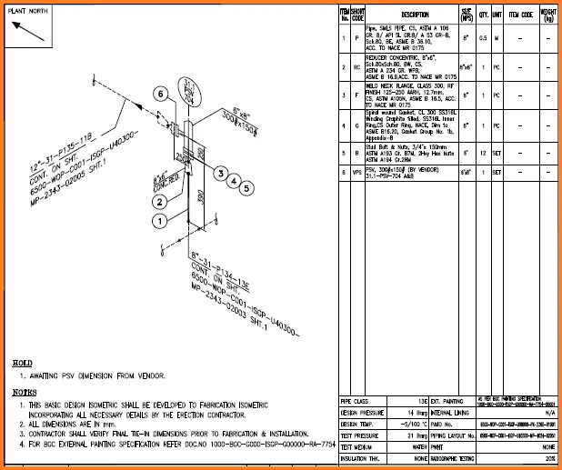
Piping Isometric drawing is one of the most important deliverables of the piping discipline as it provides complete information of the piping route to be erected at the construction site. So Engineers and Designers must be aware of the isometric preparation steps. In this article, a few of the salient points are discussed.
Piping isometrics are the three-dimensional representation of the line.
The main purpose of an isometric is to provide all information necessary for the fabrication and erection along with the bill of material required to do so.
Isometric is also used to work out the exact MTO requirement.
Generally, isometrics are prepared/extracted by the design group.
A draft person (piping designer/engineer) who knows to read the piping GA. and is conversant with a drafting tool can draft isometric.
High-point vents and low-point drains have been provided for lines that will be hydro tested. (e.g. Instrument Air, Flare, and Nitrogen lines may not be hydro tested, but pneumatically tested).
Orifice tapping orientation is as per instrument standards for gas and liquid lines.
Checking Piping Isometric Drawings before finally releasing them to the Construction team is very important. It minimizes errors and improves quality. Most of the design companies involved with isometrics prepare a piping isometric drawing checklist or isometric checklist to help Piping Isometric Checker in their activity. Also, many times piping isometrics are extracted directly from Piping Design Software. It is mandatory for the Senior Piping Checkers to check the piping isometrics thoroughly. In the tight schedule, It has to be ensured that the isometric drawings are released/ issued to clients with quality.
Checking shall be done only on a hard print as per the color code procedure by an experienced engineer/designer. Normally checklists are followed to ensure the quality of the isometrics. The new print after correction is “back checked” for incorporation.
In the following paragraphs, We will provide a few checkpoints which must be checked by the piping isometric checker for proper quality.
Piping Isometric Checklist
A Piping isometric checklist is a list of checkpoints that are ensured while checking the piping isometric. A piping isometric checker must ensure the correctness of the below-mentioned points in the piping isometric
Specific requirements mentioned in applicable P&ID notes (if any) have been complied with.
Documents Required for isometrics checking
Before starting the piping isometric checking activity, the engineer must be ready with the following drawings or documents
Piping and instrument diagram (P&ID): From this drawing, we will get information like line number, line size, insulation, fluid commodity, special notes (like no pocket, requirement of spectacle blind in equipment nozzles, pressure head, specific straight length requirement for instrument connections), etc.
Piping layouts and Sectional Drawings: Piping layouts will provide information on the pipe route, dimension, elevation, valve orientation, and coordinates.
Equipment drawings: To check details of lines connected to equipment nozzles, their elevations, etc.
Nozzle orientations: To ensure the nozzle elevation and orientation is proper.
Nozzle orientations should be kept as per the piping requirement.
Avoid obstacles. Keep piping routing neat and clear.
Control stations locate the side of near the walls or columns
Give support to the control station both sides of the control valves.
Use a dike wall around the equipment to avoiding the liquid to spread in the plant area. the volume of the dike wall is 1.5 times more than the total capacity of the equipment.
Use weld neck flange for pressure piping.
The isometric numbering is as per the approved project format and the line number matches with the isometric number.
Adequate pipe spool lengths are provided for wafer type butterfly and check valves to prevent the interference of the valve disc with adjacent piping items.
The platform/grade/building wall/dike or bund wall/floor penetrations and limits of road crossings are properly shown wherever applicable.
The insulation limits are specified appropriately (esp. for heat conservation or personal protection)
The electrical tracing requirement and its limits are specified appropriately.
The wrapping and coating requirement and its limits are specified appropriately for u/g lines.
The minimum distance between welds is 50mm or five times the wall thickness whichever is greater unless otherwise indicated in Project specifications.
Unions are provided in galvanized piping where threaded in-line items need to be removed for maintenance. Also, unions are provided at regular intervals (e.g. 24m) in straight pipe runs.
Full couplings are provided where applicable for small-bore piping.
For piping below 2”, Weld Neck flanges are not directly welded to Socket Welded fittings. Also, PE pipes are not directly welded with swaged reducers (pipe couplings are used in between).
Appropriate break-up flanges are provided in piping with internal lining and hot-dip galvanized piping (based on tub size). The spool configuration is made with one elbow or one tee only to ensure proper galvanizing.
Lifting lugs are provided for removable spools wherever required as per project requirements.
There is adequate clearance between pipe support and the adjacent piping component (e.g. flange, drain valve) to allow for flange bolt removal, valve operation, etc.
The valve stem orientation angle is indicated wherever the stem is not in the vertical and horizontal planes.
The piping interfaces with equipment/package nozzles/terminal points are checked (w.r.t. size, rating, flange face type, and nozzle/Tie-in Point nos.).
The straight length requirement for suction & discharge piping for compressors and certain pumps is as required by Vendor/project specs.
Straight lengths and branch configuration of upstream/downstream lines for anti-surge valves are as per the Compressor Vendor’s recommendation.
The Face to face dimensions of all valves, piping special items, and in-line instrument items are as per approved vendor drawings.
The instrument connections are checked with Piping-Instrument interface drawings/Instrument hook-up drawings.
The rotameters are installed in the vertical run with the flow in an upward direction.
The orifice tapping orientation is done considering liquid or gas flow as applicable and the BOM is as per the piping-instrument interface diagram.
The straight length requirement (u/s & d/s) has been provided for flow meters (e.g. flow orifices, flow nozzles, venture meters) and is as per Project standards/Vendor requirements.
The line configuration for lines containing magnetic flowmeters or vortex type flowmeters is such that they are always flooded.
Line configuration allows easy removal of spectacle blinds/spacers & blinds and valves in the case of RTJ flange joints.
Flanged spools are provided in the case of conical strainers to enable removal.
The orientation of valve handwheel/lever is checked in model for proper access and commented accordingly
Line routing is visually checked in the model for general requirements like access to inline items, supporting, clearances, obstructions, consistency and aesthetic requirement, etc.
Branches like drains, drip legs, etc. are located with sufficient clearance from the supports, steel, or other obstructions so that they do not clash during expansion/contraction.
Drip leg size and dimensions are checked with Standard drawing for steam lines.
The requirement of Weep holes for atm vent lines is indicated.
The drawing border conforms to the Project specifications or Company standards, as applicable.
The correct isometric revision number is mentioned in the title block.
Pipe class printed at the bottom of the drawing matches that in the line number.
Line data (e.g. process parameters, P&ID no., PWHT & testing requirements, insulation & painting specs, etc.) match with the Line List, if given in the isometric
Applicable reference documents (e.g. Line List, Isometric Index, Pipe Supports Spec, etc.) are mentioned.