A Pipe Coupling or Coupler plays an important role in connecting the pipe sections while maintaining the integrity of the pipes in the process. It is a very useful pipe fitting for the piping and plumbing industry. Most pipe installations require several lengths of pipe to be joined together or cut to facilitate changes in direction and crossing of obstacles. A pipe Coupling is a very short length of pipe or tube. It has socket or female pipe threads at one or both ends. Pipe coupling allows two pipes or tubes of equal or different sizes to be joined together to make a long pipe run.
The various functions that a Pipe Coupling or Coupler can serve are as follows:
- It helps to extend or terminate pipe runs.
- It can be used to change pipe size.
- It can be used to repair a broken or leaking pipe.
The body of a pipe coupling (Coupler) is typically made of either the same or similar materials as that of the pipes it joins. They may be rigid or flexible depending on the amount of movement the pipe is subjected to and may also be permanent or removable.
A pipe coupling can be increased or reduced in internal diameter to join different-sized pipes (like T or cross-shaped) to join more than two pipes, or angled to form bends. Pipe couplings, sometimes also include peripheral features like inspection openings, flow meters, or valves.
Categories of Pipe Coupling
Pipe Couplings can be categorized into two main groups.
- Permanent Coupling and
- Removable Coupling
Permanent Pipe Coupling
Permanent pipe couplings create permanent piping joints using soldering or brazing in the case of steel or copper pipes or adhesives in the case of PVC pipes. When correctly installed, these permanent joints offer excellent rigidity and sealing characteristics. Permanent Pipe Couplings are used where no future changes in the piping are foreseen.
Removable Pipe Coupling
Removable pipe couplings use threads to allow them to be screwed onto the pipes to be joined. For example, A basic pipe section slightly larger than the pipes to be joined can be cut with an internal thread to act as a removable pipe coupler. The ends of the pipes are also threaded, and the coupler is simply sealed with hemp or sealing tape and screwed onto both pipes.
Pipe Couplings Types
There are three types of coupling available
- Full Coupling
- Half Coupling
- Reducing Coupling
- Compression Coupling
- Slip Coupling / Repair Coupling
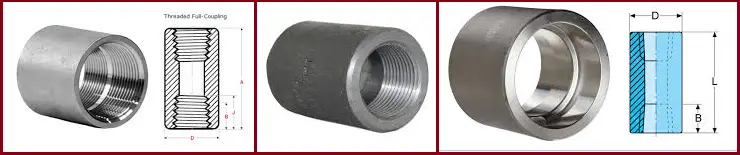
What is a Full Coupling
- Full Coupling is used for connecting small bore pipes. It is used to connect pipe to pipe or pipe to swage or nipple. It can be threaded or socket ends types.
- A socket weld full coupling is used to join small-bore plain end pipes where the pipe spec requirement is socket weld. A threaded full coupling is used to join small bore pipes with threaded ends. If the two ends of coupling are different (e.g. one BSP threaded and one NPT threaded), then it is usually referred to as an adapter.
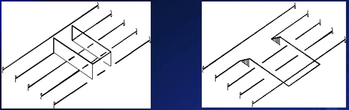
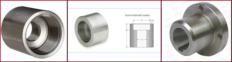
What is Half Coupling?
- Half Coupling is used for small bore branching from a vessel or large bore pipe. It can be threaded or socket type. It has a socket or thread end on only one side.
- A socket weld half coupling can be directly welded to a large bore pipe, to make a branch connection. It is used to take a small bore pipe branch-off from a large bore pipe where the pipe spec requirement is socket weld in a small bore size. A threaded half coupling only has one thread end and another end of the coupling should be a butt welding end with either a plain end or a bevel end.
Reducing Coupling
Reducing coupling is used to connect pipes of dissimilar diameters. A reducing coupling has two different sizes of threads on each side. Reducing couplings are typically used where small process feeder lines are joined into large supply circuits or where small-diameter fittings are installed.
Reducing couplers feature a simple, stepped-down profile and screw onto the two lengths of pipe in the same way a standard pipe joint does. Welded-reducing coupler designs are similar to threaded designs without threads.
Compression Coupling
A compression coupling connects two perfectly aligned pipes in which a slotted tapered sleeve is placed over the junction and two flanges are drawn over the sleeve so that they automatically center the pipes and provide sufficient contact pressure.
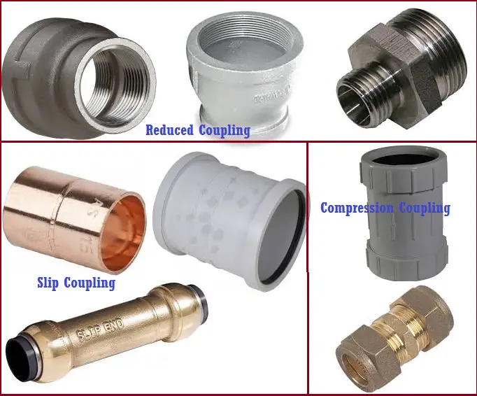
Slip Coupling / Repair Coupling
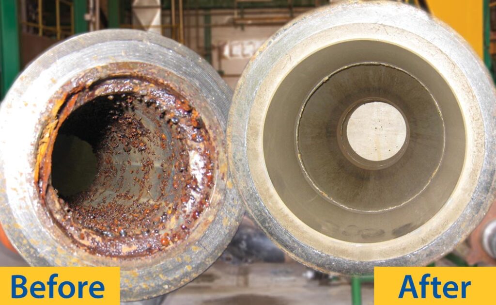
A slip coupling (sometimes also called a repair coupling) includes two pipes, one of which slides out of the other pipe to various lengths. Slip coupling is deliberately made without any internal stop, to allow it to be slipped into place in tight locations, such as the repair of a pipe that has a small leak due to corrosion or freeze bursting, or which had to be cut temporarily for some reason. The installer should carefully measure the final location of the slip coupling to ensure that it is located correctly as the alignment stop is missing.
Some important features of pipe couplings are as follows:
- Pipe Couplings come in all standard pipe sizes and are available for almost all types of pipe
- Mostly cylindrical in design.
- Available in several finishes.
- Couplings compensate for axial, lateral, and angular shaft misalignment.
- Couplings operate in a quiet and smooth way.
- There is a great degree of torsional stiffness.
- There is the right angular transmission of angular motion and torque.
- Usually long life.
- Easy mounting and dismounting.
- Low lateral stiffness etc.
Pipe Coupling Materials
Pipe couplings are made of various materials and the buyers should always consider the material used for making them. Some of the materials used for making couplings are:
- Carbon Steel
- Brass
- Aluminum
- Cast Iron
- Stainless Steel
- Copper
- Bronze, etc.
How to evaluate the couplings?
There is a long list of evaluation factors that affect the type of coupling best suited for an application. It is not necessary that all couplings will have all the features. The factors to be considered are as follows:
- Design Adaptability
- Alignment Capabilities
- Axial Freedom
- Backlash
- Chemical Resistance
- Damping Capacity
- Ease of Installation
- Fail-Safe or Fusible Link
- Field Repairable
- High-Speed Capacity
- Inherent Balance
- Maintenance Required
- Number of Component Parts
- Reciprocating Drivers and Loads
- Temperature Sensitivity
- Torque Capacity to Diameter
- Torque Overload Capacity
- Torsional Stiffness
Steel Pipe Coupling
Steel pipe couplings are widely used pipe couplings in the piping and plumbing industry. They are of two types
- Carbon Steel Pipe Coupling and
- Stainless Steel Pipe Coupling
Carbon Steel Pipe Coupling
The material standard for carbon steel pipe coupling is ASTM A105 and they are manufactured following standard ASME B16.11.
Stainless Steel Pipe Coupling
The material standard for stainless steel pipe coupling is ASTM A182, grades in F304/L or 316/L.
Differences between Full Coupling and Half Coupling
The full coupling has both ends of threaded or socket welded connection but the Half coupling is only threaded or socket welded at one end, and the other end is welded type.
Difference between Pipe Coupling and Union
The main difference between a coupling and a union is that coupling is normally used for permanent joining But a union is used for joining and disassembling a part of a piping system for fixing, maintenance or replacement.
Few more related resources for you.
Types of Reducers in the Piping Industry
Piping Elbows vs Bends: A useful literature for piping engineers
“Pipe Coupling”-A short Introduction for the piping professionals
Different Types of Hose Couplings
A Literature on Piping Nipples for piping and plumbing industry
Guidelines for Selection of Various Types of Flanges