This article is a continuation of my earlier article on Cold Springing which describes a few basic points regarding Cold Pull or Cold Springing. Click here to refer to that article.
How Cold Spring is applied on Site
The system is fabricated short as specified by the stress engineer.
The system is erected with a gap at some final closure weld, equal to the “cut shorts” in a specified direction.
Forces and moments are then applied to one or both ends, as necessary, to bring the final joint into alignment.
Pipe displacement can also be achieved by displacing supports in the vicinity of cold springs using hoists or adjustable supports. The stress engineer shall provide the movement of each restraint as required. This must appear on isometric or support drawings.
One of the ways of deciding the restraint displacement is, using the Caesar displacement report.
The other is using the following formula :- D = Dc + (C x Dh)
Where,
D = restraint displacement to be adjusted during cold springing.
Dc = Cold spring displacement without restraint.
C = Cold Spring Factor.
Dh = Hot displacement without the gap and the restraint.
Anchors are provided to preserve alignment during welding, post-weld heat treatment, and final examination.
Restraints are then removed, the resulting reactions are absorbed by the terminal points and the line is in a state of stress.
During start-up, the line expands and the levels of stress and terminal reactions will decrease as envisaged
Few Important Points related to Cold Spring:
The use of cold springs shall be avoided.
Cold springing shall only be used to limit the magnitude of forces and moments on the nozzle and not to reduce stresses.
The use of cold springs in the piping connected to rotating equipment is prohibited.
Cold springs shall not be used in the vicinity of the nozzle.
Cold springing shall be limited to a line design temperature of 3000C maximum.
Drawbacks of Cold Spring
The effectiveness of cold springs is generally considered to be questionable. It should not be used indiscriminately. Although it may provide an easy way out for an analyst to solve an equipment load problem, there are a number of considerations while adopting a cold spring in a piping system. The following points shall shed light on these factors:-
Extra anchor points, to hold the cold sprung line in position till start-up, are required. Also, extra hoists are required to move supports in the desired direction during installation. These all arrangements make cold springing a costly act.
Cold spring applied to low-temperature lines does not provide as a great benefit as it does in high-temperature lines.
The theoretical cold spring gap, which can be very helpful in low-temperature lines, is very difficult to measure and control in the field.
Due to small displacements, the effectiveness of the cold spring is unpredictable and might even produce a load that is damagingly high to the equipment.
After the plant has been operated, deliberately installed cold spring can be misunderstood to be piping misalignment when disconnected during shut down and “corrected”.
During repair, caution should be exercised when cutting into such lines as the line will be in a state of stress when cold. Proper anchoring on both sides of cut have to be planned to prevent possible accidents.
Installation procedure for every type of support adjacent to cold spring is different. Excessive care should be taken during stress analysis about knowing exact restraint displacements to achieve cold spring. Same care has to be replicated at site during construction. Any erroneous interpretation can be a starting point for disastrous situation.
Most of the times, the support adjustment/displacement can extend to few more supports than just one adjacent support. The same has to be considered and understood both at analysis and construction stage.
Special support drawing showing necessary arrangements to achieve the cold springing during erection (with the help of nearest structural member) shall be made and the loads on the respective members shall be informed to civil through piping load data.
It is required to write installation instructions of cold springing on the special support drawing and same shall be supervised at site.
Inspection & Test, Marking & Color Coding and Packing Requirements for Pipes & Fittings
The requisition engineer has to collate all the inspection & testing requirements for the piping components from the project specification & finalize the schedule in consultation with the quality department.
For marking, color coding, packing & preservation requirements requisition engineer will refer to the project specification & if that is not available he has to develop the standard procedure based on the company standard.
Inspection & Testing of Pipes and Fitting
All piping and fittings shall be inspected and tested in accordance with the relevant product standard (or code) and as stated in the Purchase requisition.
Pressure testing (Hydro-testing) of stainless steel products where required by the standard shall be performed using water having less than 30ppm of chlorides.
All welds in pipes & fittings shall be 100% radiographed in accordance with the individual ASTM Standards. Ultrasonic examination in lieu of radiography is not allowed.
Examinations and/or tests may be reviewed and/or witnessed by the contractor or their authorized third-party inspector at the vendor’s facility.
The vendor is responsible for informing the contractor about the availability of goods for inspection and testing.
The inspection shall be performed as per the “Vendor Quality Requirement form” attached with the Inquiry / Purchase requisition.
The manufacturer shall submit the certificate of conformity of the material duly certified by the inspector.
Marking & Colour Coding of Piping Systems
Marking of the piping components shall be done as per applicable codes and standards in addition to the piping item/part number, and purchase order number specified in the Material Requisition Scope of supply. For the material specified as sour service, Low Temperature (LT), or CRYOGENIC in the Material Requisition Scope of supply, the marking shall include “Sour”, “LT”, and “CRYO” respectively.
If punching or die-stamping is used for carbon, low-temperature, and alloy steel, the stamps shall be low-stress stamps (dot or round-bottomed). For stainless steel, stamping shall be electro-etched. If stenciling is used, it shall be done with indelible paint. For sizes below 1.1/2” and below the markings shall be done on attached metal tags.
Material shall be packed and ready for export in a manner that allows easy handling and prevents damage. The vendor shall submit their standard packing procedure to the purchaser for approval.
Pipe ends shall be protected with heavy-duty plastic end caps. For beveled ends, the caps shall cover the full area of the bevel.
Thin wall pipes shall not be overloaded with multi-layer of pipes while shipping. All thin wall pipes shall be braced suitably at the end to avoid ovality.
Open ends of fittings and flanges shall be supplied with heavy-duty plastic protective plugs or caps. For beveled ends, the caps shall protect the full area of the bevel.
The waterproof barrier material shall be used for stainless steel materials to protect against chlorine attack by exposure to the saltwater atmosphere.
Carbon steel and stainless steel items are not allowed to be stored together and shall be packed separately.
Online Video Course on Piping and Pipe Fittings
To enrich yourself with piping and pipe fitting details you can opt for the following online video courses
The article is about the Design of Cathodic Protection for Duplex stainless steel. The design includes many parameters like
Current density.
Coating breakdown factors.
Mass of anode.
Current output and many others.
The article mainly involves the Cathodic Protection design for the Duplex stainless steel pipeline. The Cathodic Protection design is also done for the Carbon steel pipeline(48” diameter with Al anode) and Duplex stainless steel( 24 “ diameter with Zn anode) and is compared and analyzed with the main objective, Duplex stainless steel pipeline (48” diameter with Al anode). Finally, the designs are interpreted, compared, and analyzed.
“an electrochemical protection by decreasing the corrosion potential to a level at which the corrosion rate of the metal is significantly reduced” (ISO 8044).
“a technique to reduce corrosion of a metal surface by making that surface the cathode of an electrochemical cell” (NACE RP0176).
Need for Cathodic Protection
Cathodic protection is one of the important factors in the performance of the pipeline carrying crude or petroleum products. If the pipeline has to be operated until its designed life with the least maintenance activities, Cathodic Protection is the best way to adapt. The pipeline with minimum care can lead to leaks, ruptures, etc, which affects the supply and other contract terms, which results in loss of crude or product, demand, money, time, etc.
The main motto behind Cathodic protection is “prevention is better than cure”. It’s better to design and install perfect cathodic protection rather than opting for complex and unpredictable maintenance schedules.
Fails at higher temperatures, which may result in Hydrogen Induced Stress Corrosion Cracking(HISC).
Need expertise in welding. Otherwise, it may lead to HISC, crevice corrosion, etc.
Design of Cathodic Protection
Basic inputs for cathodic protection-
Pipeline diameter for Duplex with Al anodes, D = 48”.
Length of the pipeline, LP = 71.650km.
Pipeline joint length, Lj = 12m,
Design life, T = 40 years,
Design temperature, t =45 0 c.
Corrosion coating thickness, tc = 5mm.
Mean Coating breakdown factor, fcm= 0.05.
Final Coating breakdown factor, fcf = 0.11.
The gap between half-shells, G = 100mm
Anode spacing, S = 4 joints.
Electrochemical resistivity, for seawater, ξ = 20-ohm cm.
Anode utilization factor, U = 0.8.
Mean current density, i cm or CA = 80 mA/m2
Final current densities, i cm or CF =150 mA/m2
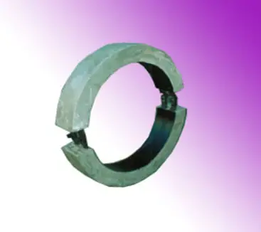
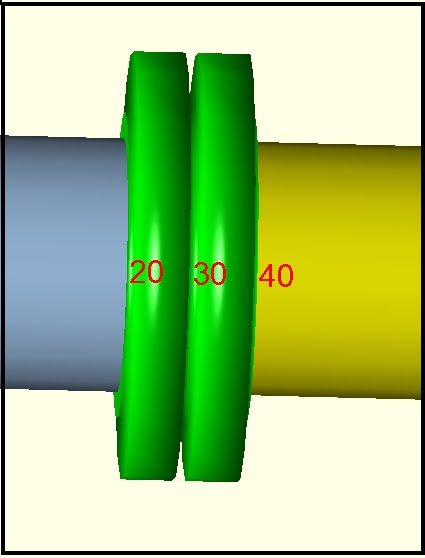
Bracelet type of anode (Fig. 3)
Fig. 3: Bracelet-type Anode
For Duplex stainless steel pipelines, the other parameters considered are:
Al Anode material density, ρ= 2700 kg/m3.
Electrochemical efficiency,ε= 1825 A-hr/kg.
Protective potential, VP = – 500V.
Closed circuit anode potential, VA = -1050 mV.
Design calculations for cathodic protection
Diameter of the anode:
Di=D+2tc=1219+(2*5)=1229mm.
Spacing
SL = S* Lj=48mm.
Number of anodes,
N = LP / SL =1493.
The net mass of each anode
MA= ᴨ/4((D+2tc)2– Di2)-2GtA)LAρ=196.2 kg
Total anode mass
M=NMA= 1493*196.2=292926.6kg.
Mean current output
IMC= εUM/T= 1219.692A
Mean current required, IMR
= CAbAᴨDLF=80* 0.05*ᴨ* 1219*71650= 1097.56A.
Final surface area per anode,
AF=ᴨ[Di+2(1-U)tA-2G]LA
=ᴨ[1229+2(1-0.8)110-2*100]150= = 0.572m2 .
Resistance of each anode,
RA=0.315ξ/√A=0.083ohm.
Final current output
IFC= N[VF – VA]/RA
= 9893.373A.
The final current required,
I FR = CFbFᴨ D LF
= 4527.451A.
The below two parameters will say whether the whole calculation for CP is feasible or not.
Mass requirement = IMC/IMR=692/1097.564= =1.11>1
Final output current = IFC/IFR = 9893.373/4527.451 = 2.19>1.
The calculations are also done for
Carbon steel pipeline with Al anode,48” dia.
Duplex stainless steel pipeline with Al anode,48” dia.
Duplex stainless steel pipeline with Zn anode,24” dia.
Results
From the calculations, it can be inferred that the Duplex stainless steel requires less amount of anodic material.
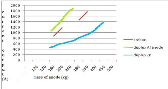
A graph (Fig. 4) is shown for the Mass of the anode (kg) vs current output(A).
Fig. 4: Mass of the anode (kg) vs current output(A)
It can be inferred that the Duplex with less amount of anodic material can give high current output, in the case of Al anode.
In the case of Zn anode for Duplex stainless steel, more anodic material is needed for maintaining the current output, because the consumption rate of Zn is more.
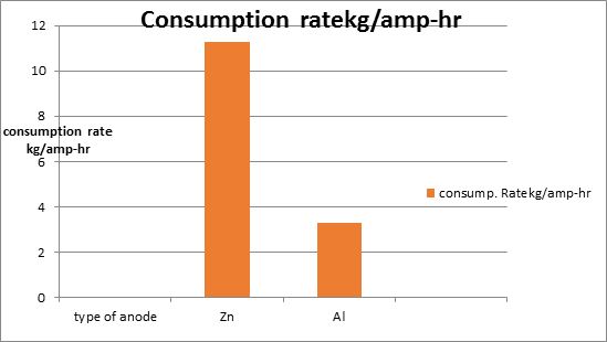
Consumption Rate (Fig. 5)
Fig. 5: Consumption rate
This graph shows the consumption rate of anodic materials. Zn anode consumption rate is higher than Al. As a result, more amount of material is needed for meeting the current demand when compared to Al.
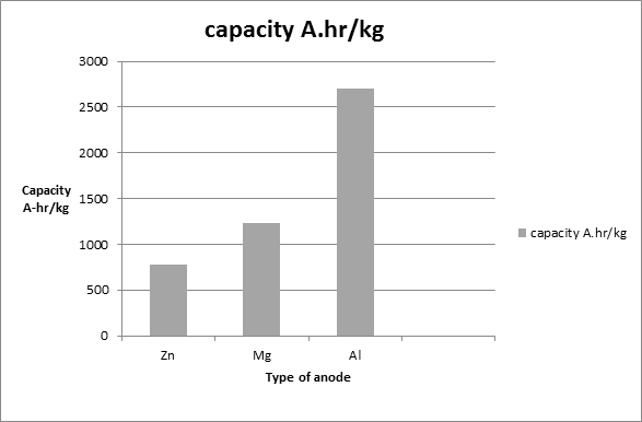
The aluminum anode is much preferable because of its high capacity compared to other anodic materials. The graph below discusses the
Capacities of anodic materials (Fig. 6):
Fig. 6: Capacities of anodic materials
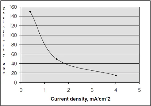
Resistivity vs Current density
From the graph below (Fig. 7), it can be inferred that the current may decrease along with the increase in resistivity.
Fig. 7: Resistivity vs Current density
Conclusion
The focus is projected on the CP design for DSS and carbon steel with the application of different anodes. The factors like the mass of anode current output etc. are concerned for the performance analysis of CP with different anodes.
It may be interpreted from the article that Duplex stainless steels with Al as anodes are best suitable for offshore applications.
Recommendations
Hg-free Aluminium sacrificial anodes are recommended for the best performance of CP in subsea pipelines.
Duplex stainless steels are best recommended for subsea pipelines because they are having good mechanical strength, high pitting corrosion, and HISC-resistant properties at normal temperatures.
Highly skilled welding to avoid flaws in the weld. The flaws may result in HISC at the welded portion of the pipeline.
Galvalum-III is the best-recommended anode certified by the DNV RP 401. It can even protect the hot oil pipelines which normal anodes may not do. These anodes are not susceptible to inter angular corrosion and can be used in place of Zn anodes.
Few more Pipeline related useful Resources for You..
Hopefully, all of you have gone through my post on Methods for checking flange leakage. In that article, I mentioned the theoretical background (analysis criteria, the basic theory behind flange leakage checking, analysis methodology, etc.) for checking flange leakage. So click here to refer to the article once again before you proceed with this article. In this current write-up, I will explain the step-by-step method for performing flange leakage analysis methodology following the Pressure Equivalent Method using Caesar II. Click here to learn the ASME Section VIII method.
Fig. 1: Typical flange in Caesar II model
Caesar II methodology for Pressure Equivalent method
Model the complete stress system from the stress isometric. It’s preferable to model each flange separately for analysis. For valve assembly, model the flanges and valves separately. Once the modeling is complete select the flanges that need to be analyzed as per the pressure equivalent method. In Fig. 1, nodes 20-30 and nodes 30-40 denote the flange assembly. Node 30 is the interface point of both flanges where flange leakage checking is required.
Inputs for Flange Analysis
Now refer to Fig. 2 provided below. Click on the Flange checks button (Checkbox) which will activate the flange input module of the Caesar II Input Screen. Now select the Flange Node(From/To/Both) and Calculation Type as shown in Fig. 2. From/To to be selected such that node 30 as mentioned above is selected in the model. For example, as node 30 is the interface point, “To” need to be selected in element 20-30 and “From” to be selected for element 30-40. Both are normally selected for flanged valves keeping the valve active. As we are performing the Pressure Equivalent method, Peq needs to be selected.
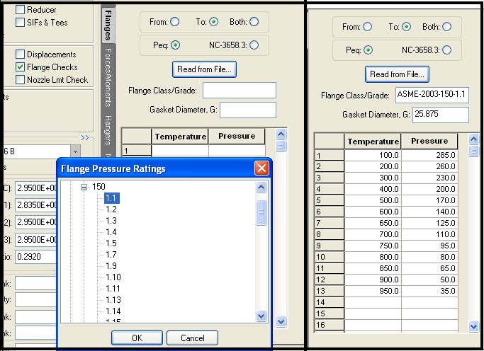
Next, Select Flange Class/Grade through the ‘Read from File’ button and refer to ASME B 16.5/ ASME B 16.47 material tables. Select flange pressure class and material grade along with governing ASBE B 16.5 code with year.
Required data will automatically be filled in. By default, the value of G will be taken as the mean gasket diameter. Users can cross-check and update the value of G as per ASME B 16.20 & ASME Sec. VIII Div. 1, Appendix 2, Table 2-5-2. based on the following equation:
b0 = 1/4, G = Mean diameter of the gasket contact face
b0 > 1/4, G = Outside diameter of gasket contact face less 2b, b=basic gasket width from code. check the above-mentioned code table for more details.
Fig. 2: Caesar II Spreadsheet typical input
Flange Leakage Checking Setting and Output Result
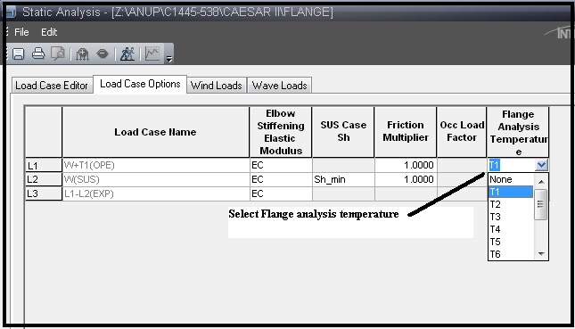
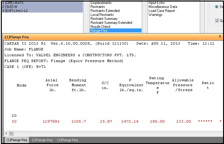
Now go to the load case editor of Caesar II and select the temperature at which flange leakage checking is to be performed as shown in Fig. 3. Normally, flange leakage is performed at the maximum design temperature. So, select that temperature. Now run the analysis to check the results. In case the calculated flange stress exceeds the allowable results will be shown in red color. The report will show the % ratio of the calculated equivalent pressure with respect to allowable. Check Fig. 4 for output results.
Fig. 3: Load Case Options module in Caesar II
Fig. 4: Caesar II flange leakage pressure equivalent output
Meaning of Pipe Schedule | Pipe Schedule Chart | Pipe Schedule 40 & 80 Dimensions
The Pipe Schedule describes the pipe wall thickness. With an increase in pipe schedule number pipe thickness increases. The main function of the pipes is to carry fluid (liquid, gas, fluidized solids, slurry, mixed-phase products, etc.) under pressure (internal, external, or both), therefore to sustain the fluid pressure the pipe has to be strong enough to perform its intended duty without failure. Obviously, for pipes containing pressurized fluids the wall thickness, and by implication the pipe’s strength, is the most important parameter. The wall thickness of the Pipe is expressed by “Schedules or Schedule numbers“, referred to as Pipe Schedules or Piping Schedules.
What is a Pipe Schedule?
The pipe Schedule or Pipe Schedule number of a Pipe is a dimensionless number that is related to Pipe Wall Thickness. The piping Schedule Number for a specific pipe size is a pipe thickness designator for that pipe size.
How to Calculate a Pipe Schedule?
Schedule Numbers for pipe size/wall thickness combinations are calculated (approximated) to get a uniform relationship equal to 1000 times the P/S (P=Design Pressure and S=Allowable Stress) expression contained in the modified Barlow formula for pipe wall thickness. The pipe schedule is abbreviated as SCH. So,
SCH=1000*(P/S)
Characteristics of Pipe Schedule
For a given pipe size and schedule the thickness of the pipe is fixed and defined in the applicable ASME standard (ASME B36.10M/ ASME B36.19M). Even though Pipe thickness can also be specified in mm or inches to the value corresponding to that specified in the ASME standard, The Schedule Numbers are strictly used as a convenient designation system while ordering piping items.
For any given pipe size and varying schedule numbers or thicknesses, its Outside Diameter (OD) remains constant and its Internal Diameter (ID) varies. With an increase in thickness, the strength increases but its ID decreases. OD is kept constant to help the support hardware design so that the same support hardware can be used for the same pipe size (varying thicknesses).
Pipe Schedule numbers can be the same for different pipe sizes but that does not mean the pipe thickness is the same. It may be the same or vary with respect to pipe sizes. For example, a 6-inch Schedule 40 pipe has 7.11 mm thickness, while an 8-inch Schedule 40 pipe has 8.18 mm thickness means thickness is increasing even though both Schedule 40.
Pipe Schedule Governing Standards
In the oil and gas and related downstream industries the most common standards are
ASME B36.10 Welded and Seamless Wrought Steel Pipe, and
ASME B36.19 Stainless Steel Pipe
What is the Nominal Pipe Size (NPS)?
The size of all pipes is identified by the nominal pipe size. The manufacture of pipe NPS 1⁄8 (DN 6) to NPS 12 (DN 300), inclusive, is based on a standardized outside diameter (OD). This OD was originally selected so that a pipe with a standard OD and a wall thickness that was typical of the period would have an inside diameter (ID) approximately equal to the nominal size. Although there is no such relation between the existing standard thickness, OD, and nominal size — these nominal sizes and standard ODs continue in use as ‘‘standard.’’
The manufacture of pipe NPS 14 (DN 350) and larger proceeds on the basis of an OD corresponding to the nominal size. So the OD in mm of a pipe NPS 14 or higher can easily be calculated by simply multiplying the NPS (here 14) by 25.4. But for lower sizes, the OD calculation is not so easy.
Pipe Schedule (SCH) vs Pipe Size
For all pipe sizes, the outside diameter remains constant.Therefore any variation in pipe schedule i.e. wall thickness affects only the inside diameter. As the pipe schedule number increases, the wall thickness increases, and the actual bore is reduced.
Standard (STD) is identical to SCH 40 up to NPS 10. All larger sizes of Standard (STD Schedule) have 9.53 mm wall thicknesses.
Extra-Strong (XS) is identical to SCH 80 up to NPS 8. All larger sizes of Extra-Strong have 12.70 mm wall thicknesses.
The double Extra Strong (XXS) wall is thicker than SCH 160 from NPS 1/8 to NPS 6, and SCH 160 is thicker than the XXS wall for NPS 8 and larger.
With an increase in pipe thickness internal diameter of the pipe reduces as the pipe’s outer diameter remains constant.
Pipe of sizes and wall thicknesses other than those of Standard, Extra-Strong, and Double Extra-Strong, and Schedule Number were adopted from API Specification 5L.
Pipe Schedule / Pipe Wall Thickness Calculation
The calculation of wall thickness varies depending on the usage of the code. All codes (B31.3, B31.1, IBR, B31.4, B31.8, nuclear code, etc.) provide equations for calculating the minimum wall thickness based on the pressure that the pipe has to withstand. The major parameters involved in thickness calculation are Design pressure, Pipe OD, and Allowable Stress at design temperature. After the calculation of minimum wall thickness, corrosion, and mechanical allowances need to be added to that. After that, the actual pipe thickness is selected (immediate higher size thickness of the calculated value) from ASME code tables depending on pipe material (CS or SS).
You may be interested in the following two articles:
A pipe size chart or pipe schedule chart is a tabular representation of pipe NPS and their thicknesses with respect to various schedule numbers. The wall thickness associated with a particular schedule depends on the pipe size. Dimensions (OD, ID, Thickness, and Schedule Number) and Weights of CS and SS pipes are given in the ASME standards mentioned above. The tables in the respective codes are dimensionally complete for all sizes and wall thicknesses within its scope, but some of the larger, heavier wall sections are beyond the capability of seamless mill production and must be obtained from forged and bored billets or other sources.
Stainless steel pipe is more often available in standard weight sizes (noted by the “S” designation, for example, “NPS SCH 10S”). However stainless steel pipe can also be available in other schedules.
Abbreviations used:
STD – Standard,
XS – Extra Strong,
XXS – Double Extra Strong,
A Pipe Schedule chart or pipe size chart is provided in the following table with respect to nominal pipe size and pipe thicknesses.
NPS
OD (in)
ID (in)
Schedules (SCH)
Pipe Wall Thick-ness (inches)
Steel Pipe Weight (lb/ft)
OD (mm)
ID (mm)
Pipe Wall Thickness (inches)
Steel Pipe Weight (kg/m)
1/8″
0.41
0.31
10, 10S
0.05
0.19
10.29
7.80
1.24
0.28
0.27
40, STD, 40S
0.07
0.24
10.29
6.83
1.73
0.36
0.22
80, XS, 80S
0.10
0.31
10.29
5.46
2.41
0.47
1/4″
0.54
0.41
10, 10S
0.07
0.33
13.72
10.41
1.65
0.49
0.36
40, STD, 40S
0.09
0.42
13.72
9.25
2.24
0.63
0.30
80, XS, 80S
0.12
0.54
13.72
7.67
3.02
0.80
3/8″
0.68
0.55
10, 10S
0.07
0.42
17.15
13.84
1.65
0.63
0.49
40, STD, 40S
0.09
0.57
17.15
12.52
2.31
0.84
0.42
80, XS, 80S
0.13
0.74
17.15
10.74
3.20
1.10
1/2″
0.84
0.67
10, 10S
0.08
0.67
21.34
17.12
2.11
1.00
0.62
40, STD, 40S
0.11
0.85
21.34
15.80
2.77
1.27
0.55
80, XS, 80S
0.15
1.09
21.34
13.87
3.73
1.62
0.47
160.00
0.19
1.30
21.34
11.84
4.75
1.94
0.25
XXS
0.29
1.71
21.34
6.40
7.47
2.55
3/4″
1.05
0.88
10, 10S
0.08
0.86
26.67
22.45
2.11
1.28
0.82
40, STD, 40S
0.11
1.13
26.67
20.93
2.87
1.68
0.74
80, XS, 80S
0.15
1.47
26.67
18.85
3.91
2.19
0.61
160.00
0.22
1.94
26.67
15.60
5.54
2.88
0.43
XXS
0.31
2.44
26.67
11.02
7.82
3.63
1″
1.32
1.10
10, 10S
0.11
1.40
33.40
27.86
2.77
2.09
1.05
40, STD, 40S
0.13
1.68
33.40
26.65
3.38
2.50
0.96
80, XS, 80S
0.18
2.17
33.40
24.31
4.55
3.23
0.82
160.00
0.25
2.84
33.40
20.70
6.35
4.23
0.60
XXS
0.36
3.66
33.40
15.22
9.09
5.45
1 1/4″
1.66
1.44
10, 10S
0.11
1.81
42.16
36.63
2.77
2.69
1.38
40, STD, 40S
0.14
2.27
42.16
35.05
3.56
3.38
1.28
80, XS, 80S
0.19
3.00
42.16
32.46
4.85
4.46
1.16
160.00
0.25
3.77
42.16
29.46
6.35
5.60
0.90
XXS
0.38
5.21
42.16
22.76
9.70
7.76
1 1/2″
1.90
1.68
10, 10S
0.11
2.09
48.26
42.72
2.77
3.10
1.61
40, STD, 40S
0.15
2.72
48.26
40.89
3.68
4.04
1.50
80, XS, 80S
0.20
3.63
48.26
38.10
5.08
5.40
1.34
160.00
0.28
4.86
48.26
33.96
7.14
7.23
1.10
XXS
0.40
6.41
48.26
27.94
10.16
9.54
2″
2.38
2.16
10, 10S
0.11
2.64
60.33
54.79
2.77
3.93
2.07
40, STD, 40S
0.15
3.85
60.33
52.50
3.91
5.73
1.94
80, XS, 80S
0.22
5.02
60.33
49.25
5.54
7.47
1.69
160.00
0.34
7.46
60.33
42.90
8.74
11.10
1.50
XXS
0.44
9.03
60.33
38.18
11.07
13.44
2 1/2″
2.88
2.64
10, 10S
0.12
3.53
73.03
66.93
3.05
5.25
2.47
40, STD, 40S
0.20
5.79
73.03
62.71
5.16
8.62
2.32
80, XS, 80S
0.28
7.65
73.03
59.00
7.01
11.39
2.13
160.00
0.38
10.01
73.03
53.98
9.53
14.90
1.77
XXS
0.55
13.70
73.03
44.98
14.02
20.39
3″
3.50
3.26
10, 10S
0.12
4.33
88.90
82.80
3.05
6.45
3.07
40, STD, 40S
0.22
7.58
88.90
77.93
5.49
11.27
2.90
80, XS, 80S
0.30
10.25
88.90
73.66
7.62
15.25
2.62
160.00
0.44
14.32
88.90
66.65
11.13
21.31
2.30
XXS
0.60
18.58
88.90
58.42
15.24
27.65
3 1/2″
4.00
3.76
10, 10S
0.12
4.94
101.60
95.50
3.05
7.35
3.55
40, STD, 40S
0.23
9.11
101.60
90.12
5.74
13.56
3.36
80, XS, 80S
0.32
12.51
101.60
85.45
8.08
18.62
2.73
XXS
0.64
22.85
101.60
69.29
16.15
34.00
4″
4.50
4.26
10, 10S
0.12
5.61
114.30
108.20
3.05
8.35
4.03
40, STD, 40S
0.24
10.79
114.30
102.26
6.02
16.06
3.83
80, XS, 80S
0.34
14.98
114.30
97.18
8.56
22.29
3.62
120.00
0.44
19.00
114.30
92.05
11.13
28.28
3.44
160.00
0.53
22.51
114.30
87.33
13.49
33.50
3.15
XXS
0.67
27.54
114.30
80.06
17.12
40.98
4 1/2″
5.00
4.51
STD, 40S
0.25
12.54
127.00
114.45
6.27
18.66
4.29
XS, 80S
0.36
17.61
127.00
108.97
9.02
26.21
5″
5.56
5.30
10, 10S
0.13
7.77
141.30
134.49
3.40
11.56
5.05
40, STD, 40S
0.26
14.62
141.30
128.19
6.55
21.76
4.81
80, XS, 80S
0.38
20.78
141.30
122.25
9.53
30.92
4.56
120.00
0.50
27.04
141.30
115.90
12.70
40.24
4.31
160.00
0.63
32.96
141.30
109.55
15.88
49.05
4.06
XXS
0.75
38.55
141.30
103.20
19.05
57.37
6″
6.63
6.36
10, 10S
0.13
9.29
168.28
161.47
3.40
13.83
6.07
40, STD, 40S
0.28
18.97
168.28
154.05
7.11
28.23
5.76
80, XS, 80S
0.43
28.57
168.28
146.33
10.97
42.52
5.50
120.00
0.56
35.39
168.28
139.73
14.27
52.67
5.19
160.00
0.72
43.35
168.28
131.80
18.26
64.51
4.90
XXS
0.86
53.16
168.28
124.38
21.95
79.11
8″
8.63
8.33
10, 10S
0.15
13.40
219.08
211.56
3.76
19.94
8.13
20.00
0.25
22.36
219.08
206.38
6.35
33.28
8.07
30.00
0.28
24.70
219.08
205.00
7.04
36.76
7.98
40, STD, 40S
0.32
28.55
219.08
202.72
8.18
42.49
7.81
60.00
0.41
35.64
219.08
198.45
10.31
53.04
7.63
80, XS, 80S
0.50
43.39
219.08
193.68
12.70
64.57
7.44
100.00
0.59
50.95
219.08
188.95
15.09
75.82
7.19
120.00
0.72
61.71
219.08
182.60
18.26
91.83
7.00
140.00
0.81
67.76
219.08
177.83
20.62
100.84
6.81
160.00
0.91
74.79
219.08
173.05
23.01
111.30
6.88
XXS
0.88
72.42
219.08
174.63
22.23
107.77
10″
10.75
10.42
10, 10S
0.17
18.65
273.05
264.67
4.19
27.75
10.25
20.00
0.25
28.04
273.05
260.35
6.35
41.73
10.14
30.00
0.31
34.24
273.05
257.45
7.80
50.95
10.02
40, STD, 40S
0.37
40.48
273.05
254.51
9.27
60.24
9.75
60, XS, 80S
0.50
54.74
273.05
247.65
12.70
81.46
9.56
80.00
0.59
64.43
273.05
242.93
15.09
95.88
9.31
100.00
0.72
77.03
273.05
236.58
18.26
114.63
9.06
120.00
0.84
82.29
273.05
230.23
21.44
122.46
8.75
140, XXS
1.00
104.10
273.05
222.25
25.40
154.92
8.50
160.00
1.13
115.60
273.05
215.90
28.58
172.03
12″
12.75
12.39
10, 10S
0.18
24.16
323.85
314.71
4.57
35.95
12.25
20.00
0.25
33.38
323.85
311.15
6.35
49.67
12.09
30.00
0.33
43.77
323.85
307.09
8.38
65.14
12.00
STD, 40S
0.38
49.56
323.85
304.80
9.53
73.75
11.94
40.00
0.41
53.52
323.85
303.23
10.31
79.65
11.75
XS, 80S
0.50
65.42
323.85
298.45
12.70
97.36
11.63
60.00
0.56
73.15
323.85
295.30
14.27
108.86
11.38
80.00
0.69
88.63
323.85
288.95
17.48
131.90
11.06
100.00
0.84
107.90
323.85
281.03
21.44
160.57
10.75
120, XXS
1.00
125.50
323.85
273.05
25.40
186.76
10.50
140.00
1.13
136.70
323.85
266.70
28.58
203.43
10.13
160.00
1.31
150.30
323.85
257.20
33.32
223.67
14″
14.00
13.62
10S
0.19
27.73
355.60
346.05
4.78
41.27
13.50
10.00
0.25
36.71
355.60
342.90
6.35
54.63
13.38
20.00
0.31
45.61
355.60
339.73
7.92
67.88
13.25
30, STD, 40S
0.38
54.57
355.60
336.55
9.53
81.21
13.12
40.00
0.44
63.44
355.60
333.35
11.13
94.41
13.00
XS, 80S
0.50
72.09
355.60
330.20
12.70
107.28
12.81
60.00
0.59
85.05
355.60
325.48
15.09
126.57
12.50
80.00
0.75
106.10
355.60
317.50
19.05
157.89
12.12
100.00
0.94
130.90
355.60
307.95
23.83
194.80
11.81
120.00
1.09
150.80
355.60
300.08
27.69
224.42
11.50
140.00
1.25
170.20
355.60
292.10
31.75
253.29
11.19
160.00
1.41
189.10
355.60
284.18
35.71
281.41
16″
16.00
15.62
10S
0.19
31.75
406.40
396.85
4.78
47.25
15.50
10.00
0.25
42.05
406.40
393.70
6.35
62.58
15.38
20.00
0.31
52.27
406.40
390.53
7.92
77.79
15.25
30, STD, 40S
0.38
62.58
406.40
387.35
9.53
93.13
15.00
40, XS, 80S
0.50
82.77
406.40
381.00
12.70
123.18
14.69
60.00
0.66
107.50
406.40
373.08
16.66
159.98
14.31
80.00
0.84
136.60
406.40
363.58
21.44
203.28
13.94
100.00
1.03
164.80
406.40
354.03
26.19
245.25
13.56
120.00
1.22
192.40
406.40
344.53
30.99
286.32
13.12
140.00
1.44
223.60
406.40
333.35
36.53
332.75
12.81
160.00
1.59
245.30
406.40
325.48
40.49
365.05
18″
18.00
17.62
10S
0.19
35.76
457.20
447.65
4.78
53.22
17.50
10.00
0.25
47.99
457.20
444.50
6.35
71.42
17.38
20.00
0.31
58.94
457.20
441.33
7.92
87.71
17.25
STD, 40S
0.38
70.59
457.20
438.15
9.53
105.05
17.12
30.00
0.44
82.15
457.20
434.95
11.13
122.25
17.00
XS, 80S
0.50
93.45
457.20
431.80
12.70
139.07
16.88
40.00
0.56
104.70
457.20
428.65
14.27
155.81
16.50
60.00
0.75
138.20
457.20
419.10
19.05
205.66
16.13
80.00
0.94
170.90
457.20
409.60
23.83
254.33
15.69
100.00
1.16
208.00
457.20
398.48
29.36
309.54
15.25
120.00
1.38
244.10
457.20
387.35
35.05
363.26
14.88
140.00
1.56
274.20
457.20
377.85
39.67
408.05
14.44
160.00
1.78
308.50
457.20
366.73
45.24
459.10
20″
20.00
19.56
10S
0.22
48.05
508.00
496.93
5.54
71.51
19.50
10.00
0.25
52.73
508.00
495.30
6.35
78.47
19.25
20, STD, 40S
0.38
78.60
508.00
488.95
9.53
116.97
19.00
30, XS, 80S
0.50
104.10
508.00
482.60
12.70
154.92
18.81
40.00
0.59
123.10
508.00
477.82
15.09
183.19
18.38
60.00
0.81
155.40
508.00
466.75
20.62
231.26
17.94
80.00
1.03
208.90
508.00
455.63
26.19
310.88
17.44
100.00
1.28
256.10
508.00
442.93
32.54
381.12
17.00
120.00
1.50
296.40
508.00
431.80
38.10
441.09
16.50
140.00
1.75
341.10
508.00
419.10
44.45
507.61
16.06
160.00
1.97
379.20
508.00
408.03
50.01
564.31
24″
24.00
23.50
10, 10S
0.25
63.41
609.60
596.90
6.35
94.36
23.25
20, STD, 40S
0.38
96.42
609.60
590.55
9.53
143.49
23.00
XS, 80S
0.50
125.50
609.60
584.20
12.70
186.76
22.88
30.00
0.56
140.70
609.60
581.05
14.27
209.38
22.63
40.00
0.69
171.30
609.60
574.70
17.48
254.92
22.06
60.00
0.97
238.40
609.60
560.43
24.61
354.78
21.56
80.00
1.22
296.80
609.60
547.73
30.96
441.69
20.94
100.00
1.53
357.40
609.60
531.83
38.89
531.87
20.38
120.00
1.81
429.40
609.60
517.55
46.02
639.02
19.88
140.00
2.06
483.10
609.60
504.85
52.37
718.93
19.31
160.00
2.34
542.10
609.60
490.58
59.54
806.73
30″
30.00
29.38
10, 10S
0.31
98.93
762.00
746.15
7.92
147.22
29.25
STD, 40S
0.38
118.65
762.00
742.95
9.53
176.57
29.00
20, XS, 80S
0.50
157.53
762.00
736.60
12.70
234.43
28.75
30.00
0.63
196.06
762.00
730.25
15.88
291.77
36″
36.00
35.38
10.00
0.31
118.92
914.40
898.55
7.92
176.97
35.25
STD, 40S
0.38
142.68
914.40
895.35
9.53
212.33
35.00
XS, 80S
0.50
189.57
914.40
889.00
12.70
282.11
34.75
30.00
0.63
235.13
914.40
882.65
15.88
349.91
48″
48.00
47.25
STD, 40S
0.38
190.74
1219.20
1200.20
9.53
283.85
47.00
XS, 80S
0.50
253.65
1219.20
1193.80
12.70
377.47
Table 1: Pipe Schedule Chart
Pipe Schedule 40 Dimensions
Pipe Schedule 40 is a basic pipe thickness designator. It only denotes that for a given material, Sch 40 Pipes can withstand certain pressures. Schedule 40 for a pipe is identical to Schedule STD for pipe sizes up to NPS 10.
The following table will provide an example of Schedule 40 Steel Pipe Dimensions.
Pipe Schedule 80 has more thicknesses as compared to SCH 40 pipes. So, automatically Sch 80 Steel Pipes are stronger. The following table provides the dimensions for Pipe Schedule 80 Steel Pipes.
Nominal size, NPS
Outside diameter, in
Wall thickness, in
Weight, lb/ft
Outside diameter, mm
Wall thickness, mm
Weight, kg/m
1/8
0.405
0.095
0.31
10.3
2.41
0.47
1/4
0.54
0.119
0.54
13.7
3.02
0.8
1/2
0.84
0.147
1.09
21.3
3.73
1.62
3/4
1.05
0.154
1.47
26.7
3.91
2.2
1
1.315
0.179
2.17
33.4
4.55
3.24
1 1/4
1.66
0.191
3
42.2
4.85
4.47
1 1/2
1.9
0.2
3.63
48.3
5.08
5.41
2
2.375
0.218
5.02
60.3
5.54
7.48
2 1/2
2.875
0.276
7.66
73
7.01
11.41
3
3.5
0.3
10.25
88.9
7.62
15.27
3 1/2
4
0.318
12.5
101.6
8.08
18.63
4
4.5
0.337
14.98
114.3
8.56
22.32
5
5.563
0.375
20.78
141.3
9.53
30.97
6
6.625
0.432
28.57
168.3
10.97
42.56
8
8.625
0.5
43.39
219.1
12.7
64.64
10
10.75
0.594
64.43
273
15.09
96.01
12
12.75
0.688
88.63
323.8
17.48
132.08
14
14
0.75
106.13
355.6
19.05
158.1
16
16
0.844
136.61
406.4
21.44
203.53
18
18
0.938
170.92
457
23.83
254.55
20
20
1.031
208.87
508
26.19
311.17
24
24
1.125
296.58
610
30.96
442.08
Table 3: Schedule 80 Pipe Dimensions
Details about CAESAR II Error: “Material is Outside the Temperature Range”.
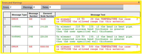
While working with Caesar II software, many of you must have received a message stating that the material is outside the temperature range (Refer to Fig. 1) even though you know/believe that you are operating your piping system within allowed temperature limits in CAESAR II.
Fig. 1: Figure showing typical CAESAR II Error: “Material is Outside the Temperature Range”.
You are sure that you have entered temperatures that are allowed for the material, but still, the error is showing. The main reason could be found easily if you check the ambient temperature used for stress analysis of that material. Normally most of the piping codes publish material expansion coefficient data from 70 degrees F onwards that is why it is the CAESAR II default ambient temperature value. So if you have used ambient temperature less than 70 degrees F (21.12 degrees C) you may find the above-mentioned error while running the Caesar file because it could be a case of missing expansion coefficient data in the material database.
The Solution:
So what can you do in such situations? Well, you have two choices:
Increase the ambient temperature to 70 F, which may not be accepted and thus not allowed because due to harsh environmental conditions, you may have selected a lower ambient temperature.
Add the missing expansion coefficient to the material database. This could be the right approach.
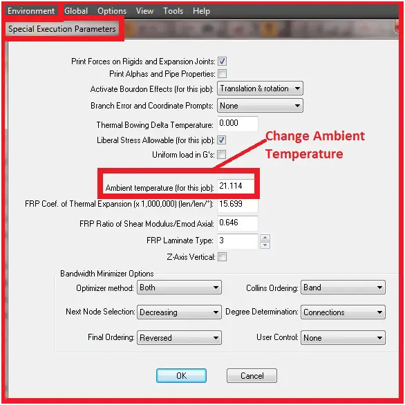
Changing the Ambient Temperature:
If you plan to change the ambient temperature, open the piping input spreadsheet and select Environment->Special Execution Parameters. Refer to Fig. 2.
Fig. 2: Figure showing the procedure to change the ambient temperature
Changing the Expansion Coefficient:
To update or add the expansion coefficient for the specific material you have to follow the following steps:
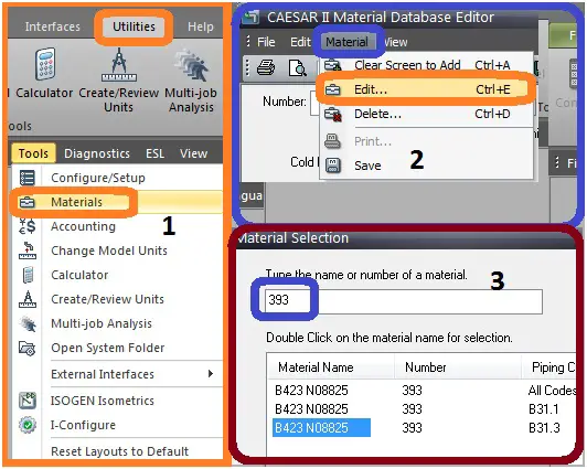
From the CAESAR II main menu, select Utilities-> Tools->Materials (Refer to Fig. 3-1)
It will open the material database editor. Then in the Material Database Editor, select Material->Edit (Refer to Fig. 3-2)
Next, in the search box type in the material number and click Search or press Enter on the keyboard (Refer to Fig. 3-3).
Double-click on the Material Name that corresponds to the piping code you are using (Refer to Fig. 3-3).
Fig. 3: Figure showing the editing procedure for a typical material in Caesar II database value
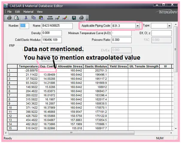
On double-clicking, the material name a window similar to Fig 4 will open and the screen will be available for editing. The highlighted cell shows that the expansion coefficient does not exist below 70 F. In this case, you have to extrapolate the value for the mentioned temperature and add it here. Take precautions to edit the cell because the piping codes may have restrictions on the minimum metal temperature that you are allowing for the given material.
Fig. 4: Caesar II material database editor.
Now simply type in your calculated extrapolated value and then select Material->Save.
Now change the Applicable Piping Code (Fig. 4) to the right of the material Name to ALL CODES, and select Material->save again.
At this point, you are ready to use this material in your CAESAR II input file. Remember that these changes do not affect the CAESAR II material database as the changes are stored in a user-defined database. However, user-defined materials are used by default in place of the CAESAR II material entries when new files are created.
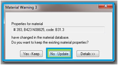
When you next open your input file you will be prompted that the material properties have changed as shown in Fig. 5.
Fig. 5: Prompt showing that material properties have changed.
You should select the No-Update option (Fig. 5) to read in the new material properties and begin using your material in your input file. Now the error checker will not show the earlier material error and the problem will be solved.