Vibration monitoring can be defined as the monitoring of the rotary equipment (pumps, compressors, turbines, fans, etc.) using a set of tools to find out equipment health continuously or at a predetermined interval that can develop vibration (or equipment malfunction) in the system. These tools sense the vibration signals and convert them into some physical phenomena so that the condition of the equipment’s health is determined. In this article, we will explore the vibration monitoring basics.
Why is vibration monitoring important?
Vibration with plant machinery is a serious problem with plant operations. Its severity sometimes leads to even plant shutdown. So It must be monitored. Vibration monitoring systems help to detect equipment damage or malfunction in good time to prevent major consequences like equipment failure or plant downtime.
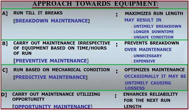
Machinery in an operating plant requires attention to perform at desired levels of performance-approach towards equipment. Various types of maintenance approaches are taken for rotary equipment as listed in Fig. 1:
Fig. 1: Normal Approaches towards Equipment
Condition Monitoring
The main advantages of condition monitoring are:
Extended asset life
Reduced maintenance costs
Cost savings on prematurely replaced resources
Reduced downtime
Condition monitoring can be of two types:
A) Vibration Monitoring: Online vibration monitoring and Offline Vibration Monitoring.
B) Lubricating Oil Monitoring: Oil properties analysis and wear Debris analysis.
Online Monitoring
In Online condition monitoring, the rotary equipment is continuously monitored. So, online monitoring is a non-interrupted permanent process that produces data continuously including the most critical moments.
Fig. 2: Typical online monitoring system
The major features of online vibration monitoring are:
Permanently mounted probes.
All rotary equipment above 500 KW.
Bently Nevada makes systems
Shaft Vibration as well as Casing Vibration.
Provide real-time data for equipment health.
Vibration sensors are wirelessly connected to a remote condition monitoring system.
Online vibration monitoring is applied to:
Monitor Highly Critical Assets
Monitor Troubled Assets
Monitor Hard-to-Reach Assets
Offline Monitoring
Offline vibration monitoring is employed for less critical equipment where a periodic check is sufficient. Manual or Semi-automated equipment is used for offline monitoring. The main features of offline condition monitoring are
Oil Condition – Oil Degradation, Metals, Wear Particles in Oil.
Three Stages in Vibration Monitoring
What to measure from the machine? Identification of parameters and machine
How to measure? Instrumentation requirement
When to measure? Frequency of CM
Basics of Vibration
What is Vibration?
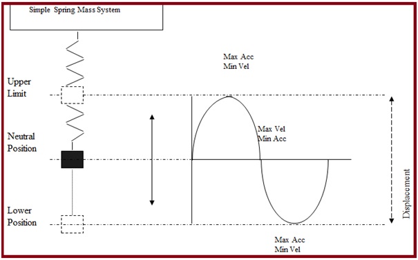
Vibration can be defined as the cyclic or oscillating motion of a component from its mean position.
Fig. 3: Vibration of Simple Spring Mass System
Units of Vibration Measurement
Displacement: m, mm, microns. mils
Velocity: m/sec, mm/sec, in/sec
Acceleration : m/sec2, g
What causes Vibration?
Various factors can cause vibration in a system like
Unbalance
Misalignment
Shaft and Bearing Wear
Bent shaft
Mechanical Looseness
Eccentricity
Resonance
Anti-friction bearing
Journal bearing
Aerodynamics and hydraulic problem
Electrical problem
Gear problem
Belt-drives problem
Bearing Failure
Units of Vibration:
Amplitude: It is the magnitude of the vibration signal. How much is it vibrating? Size (severity) of the problem.
Frequency: How many times does oscillation occur for a given time period? What is vibrating? Source of the vibration.
Phase Angle: The Phase Angle is the angle (in degrees) the shaft travels from the start of data collection to when the sensor experiences maximum positive force. How is it vibrating? Cause of the vibration.
Units of Amplitude
Displacement: The distance a structure moves or vibrates from its reference or rest position.
Velocity: Rate of change of displacement. It is the measure of the speed at which the mass is vibrating during its oscillation.
Acceleration: It is the rate of change of velocity. The greater the rate of change of velocity the greater the forces (F=ma) on the machines.
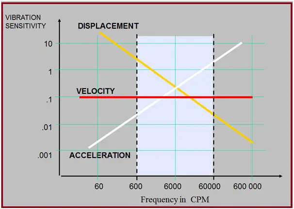
When To Use Displacement / Velocity / Acceleration (Fig. 4)?
Fig. 4: When to Use Displacement-Velocity-Acceleration
Systems / Tools for Vibration Monitoring
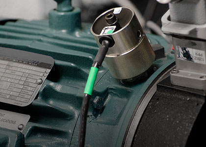
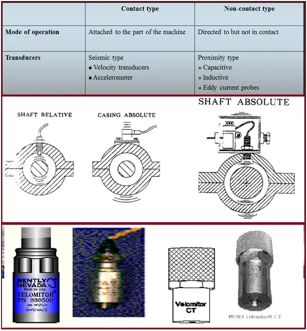
Transducers (Fig. 5):
It is a basic device, which converts mechanical motion into an electrical signal which can be amplified, filtered, analyzed, and displayed to indicate the vibrations and allow diagnosis of the overall machinery health.
Fig. 5: Use of transducers for vibration monitoring
Seismic Sensor –
Works on piezo-electrical / moving coil principle
Indirect measurement of shaft vibration.
Directly mounted on machine casing / bearing house.
Absolute vibration in terms of mm/sec or g
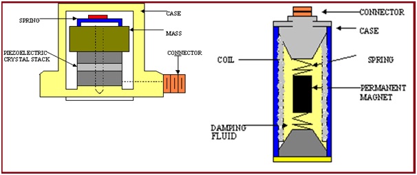
The VELOCITY PICK-UP is a contact-type transducer.
Within the velocity pick-up, a spring-mass suspension system is used, which is designed to have a low frequency. It is a permanent magnet mass suspended on a spring and surrounded by a coil attached to the protective housing. Damping fluid is used to dampen the natural frequency Velocity pick-up is limited to low frequency (between 10 Hz and 1500 Hz) for practical purposes.
Accelerometer (Fig. 6)
The accelerometer consists of a stack of piezoelectric crystals (such as quartz) to which a mass is attached.
When a piezoelectric crystal is stressed, it produces an electric voltage output that is proportional to the stress/force. When the accelerometer is attached to a vibration body, the crystal is stressed by the inertia of the mass caused due to the vibration. The electrical voltage output is proportional to the vibration acceleration.
Fig. 6: Several types of transducers.
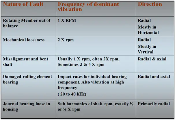
Vibration Signals for Vibration Monitoring
A frequency that is an integral multiple (´2, ´3, etc.) of a fundamental (´1) frequency.
Sub-harmonic- A frequency that is an integral submultiple (´1/2, ´1/3, etc.) of a fundamental (´1) frequency.
Vibration components (on rotating machinery) that are related to shaft speed.
Sub-synchronous- Components of a vibration signal whose frequency is less than 1´ shaft speed.
Fig. 7: Dominant frequency vs Nature of Fault
Unidirectional vibrations. i.e. severity is more in radial directions as compared to axial.
The phase difference is 90° in radial directions.
Highly sensible w.r.t. machine rpm. It is directly proportional to machine speed.
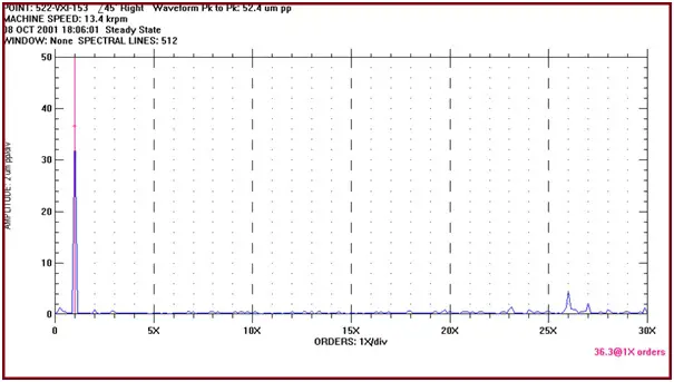
Frequency Spectrum(Fig. 8) for Vibration monitoring data
Frequency Spectrum is a plot of frequency V/s amplitude. The frequency axis may be scaled indirect frequency units Hz or in order of shaft rotative speed ie. 1X, 2X, etc. depending on the requirement. Baseline data can also be superimposed on the existing data to view changes in rotor response from known conditions.
Fig. 8: Sample frequency spectrum plot
BODE PLOT (Fig. 9) for Vibration Monitoring Data
Bode Plot is a transient data plot and the display is either 1X or 2X vibration amplitude and phase with respect to shaft rotative speed. This plot is only available as startup or shutdown data. This plot is useful in determining the slow roll speed range, balance resonant frequencies, synchronous amplification factor, heavy spot location, and rotor mode shape.
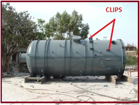
The attachments welded to the equipment by the vendor for bolting the brackets for pipe support are known as Pressure Vessel clips or Cleats. Fig. 1 shows typical clips for a horizontal pressure vessel. Pressure Vessel clips are used mainly for supporting purposes. They are also known as Vessel attachments or Vessel Cleats and form a major pressure vessel attachment part.
Fig. 1: Vessel clips
Features of Vessel Clips
Equipment requires hydro/ pneumatic testing at the vendors’ workshop to check leakage possibility and after the testing, no welding is permitted on the equipment as it may require stress relieving, radiography, and subsequently re-hydro testing. Also, brackets are not welded directly to the vessel as it is difficult to transport and erect the equipment at the site. So vendors provide clips or cleats in the form of extended attachments from the vessel plate at the required locations specified by the piping team.
Vessel clip information is furnished to the mechanical static equipment department which they forward to the equipment vendor/manufacturer along with nozzle orientation.
The vendor prepares a surface development drawing of the vessel and can check the fouling with weld seam and neighboring nozzles or clips.
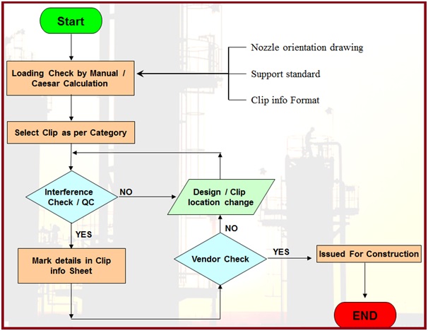
Vessel Clip Selection Procedure
Refer to Fig. 2 for a flow diagram of the Pressure Vessel Clip selection procedure.
The Vessel clip should be able to take the worst load combination possible as per stress analysis criteria.
Operating load: pipe metal weight +pipe component weight like a valve, flanges etc.+ Insulation + fluid + thermal load (at operating/ design conditions).
Hydrotesting load: clip load during the hydro test ( Without insulation)
Occasional loads: pipe metal weight + pipe component weight like a valve, flange etc.+ Insulation wt.+ Fluid weight+ thermal load at operating (not at design conditions)+ wind/ seismic load.
Few Salient Points
The following points are to be kept in mind while providing clip-loading information.
If a vapor line is to be hydro-tested and its load is exceeding the vessel cleat/clip allowable: In that case, the line can be hydro-tested (along with the column) at the ground and can be erected with the column.
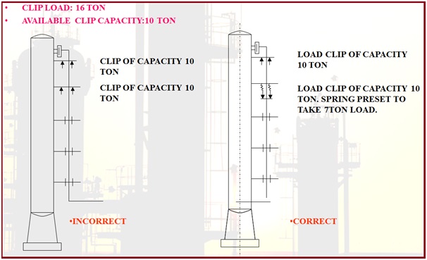
If the operating load is more than the equipment cleat capacity: A second load-taking support (usually spring support) is used as shown in Fig. 3 below.
Fig. 3: Clip Selection guideline in case the operating load is more than Clip Capacity
How to Choose the Location of the Vessel Cleat
Follow the below-mentioned steps while selecting the vessel clip location.
Width of bracket: based on insulation the width of the bracket
Bracket length limitations
Fouling: bracket should not foul with the adjacent bracket, adjacent pipe, weld joint of elbow, the pad of nozzle
How to Avoid Fouling with Vessel Clip
By staggering the supports
By changing the orientation of the line
Choosing the suitable bracket
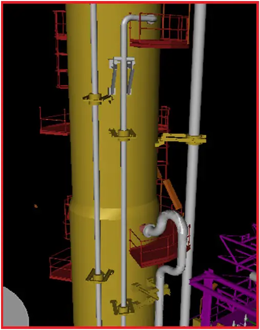
Fig. 4 shows a typical pipe supported by vessel clips.
Fig. 4: Typical Piping System supported by Vessel Clips
Usual Equipment having Cleat or Clip Supports
Supporting pipes using clips or cleats is more common for towers or columns. However, sometimes the cleat support is taken from the following equipment to support pipes.
If you wish to learn more about Pressure Vessels, their design, fabrication, installation, etc in depth, then the following online courses will surely help you:
The term TBE i.e, Technical Bid Evaluation is well-known to all piping engineers. Whenever any piping item is purchased from a vendor, before placing the final order, it is required to check the technical requirements of the items. This will ensure that the item is meeting all technical requirements for which the item is intended.
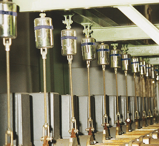
In a similar way, all spring hanger (both variable and constant) quotations received from spring hanger vendors (vendor drawings) are checked thoroughly. The following write-up will provide a guideline about the major points which must be checked for the Spring hangers to work properly.
Spring hot load, Cold load, Spring rate, Variability
It is intended that the vendor spring datasheet should meet the client’s spring hanger datasheet exactly. If at the start of the project, the spring vendor is decided and the offer is taken from that decided vendor then all the above-mentioned data will match exactly.
However sometimes it is not possible to determine the spring vendor at the start of the project and all springs are designed based on any standard spring vendor (such as the Lisega, Carpentar & Patterson, Piping Technology and Products, Anvil, or any other) and when the final order is placed from some other vendor the data varies. So in this context, the Piping Engineer (Materials engineer or Pipe Stress engineer) should check the acceptability of each Spring hanger.
Normal practice is to match the hot load exactly as that is the load the spring hanger will carry during operation. And because of different spring rates depending on the vendor, the cold load will vary. However, it is required to match the Spring rate as nearer as possible So the Cold load will also be nearer to the client datasheet value. A mismatch of roughly +/-5% is acceptable for Static equipment and Centrifugal Pump connected lines. For highly strain sensitive critical rotary equipment like Steam turbine, Centrifugal compressor, etc connected lines the stress engineer should input the exact offer values and verify the stress results.
In addition to the above, it is to be checked that the hot load and cold load lie within the range provided by the catalog. The variability is also to be checked and to be kept within 25% (10% for rotary equipment connected lines).
Overall Spring Height with all attachments
One of the major points which sometimes missed out for checking is Elevation or overall spring height (In certain cases Spring casing diameter). One should critically check the actual space available and the space required for placing the spring hanger. If the overall height with all attachments is more than the available space in the construction site then the Spring hanger needs to be rejected or the vendor is required to provide a separate revised offer for that spring. During the initial design phase, it is better to keep some extra space for the spring hanger assembly as that can be later adjusted after receipt of the actual vendor offer by adjusting rod length for top-mounted springs or by adjusting dummy length or shoe height for bottom-mounted springs.
Attachment Materials
The spring hanger (top-mounted Springs) attachments that will be directly in contact with the pipe like lug, clamp, etc should of similar material as that of the pipe. This must be ensured while doing TBE.
PTFE or SS plate requirements
Sometimes for bottom-mounted spring hangers PTFE or SS plate is required above the spring load flanges. While performing TBE it is to be checked whether the PTFE/ SS plate of proper dimension is provided by the vendor or not as well as provided as a loose item or attached with a load flange. The height of these items is to be included in over-spring height while designing or making datasheets.
Other Miscellaneous data
Some other miscellaneous data are required to be checked which are listed below:
Whether the items supplied are corrosion-resistant or not?
Whether Spring coil is coated or not?
Whether all testing requirements are met?
The vendor should properly indicate the cold (Blue mark) and hot loads (Red mark) properly.
Whether travel stoppers/preset pins are properly installed or not?
Whether all items are painted as per governing specifications or not?
A sway brace is a mechanical device used in process and power plants to reduce the vibration tendency by absorbing shock loadings. They contain a spring-loaded mechanism that provides opposing force for dynamic events (vibration, sway) in both a tension and compression mode while allowing pipe thermal movement. So whenever vibration or any dynamic event occurs the spring force of the sway brace acts in the opposite direction and brings the system back to normal operating condition by absorbing that vibrational force.
In this article, I will explain the procedure for modeling Sway Braces in Caesar II.
Sway braces are spring (pre-loaded) loaded units to limit the swaying or vibration induced by external forces by applying an opposing force on the pipe. The sway brace is simulated by the use of bi-linear restraint available in CAESAR II. It will be discussed in the following section.
Modeling Sway Brace in Caesar II
The steps involved in modeling a sway brace in Caesar are as follows:
Select the sway brace from the catalog depending on the given pipe’s nominal diameter or depending on the force calculated to restrain the pipework. (Fig. SB45 as per the C&P catalog reproduced in Fig. 1)
Fig.1: Sway Brace selection Table from C&P Catalogue.
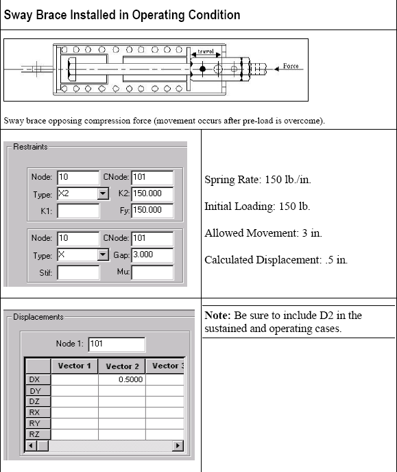
2. Mark a node (Node 10-Fig.2) at the location in the piping system where the sway brace will be installed. Run Caesar analysis and note down the displacement of the point in the specified direction from cold to operating condition. For the sake of example, let’s assume that CAESAR II calculated displacement from cold to operating position is 0.5 inch in +X direction.
3. Now in the CAESAR II input spreadsheet (See Fig. 2) check the restraints box and define bi-linear restraint (X2 for the assumed case) at Node 10 with C-Node at 101. Here, K1 is the initial stiffness of a bi-linear restraint. Do not enter anything on this cell as the restraint is assumed to be rigid. The value of Fy is to be obtained from the catalog. Where K2= Post yield stiffness of a bilinear restraint. When the load on the support restraint exceeds Fy then the stiffness on the support restraint changes from K1 to K2. Fy = Yield Load. If the load on the support restraint is less than “Fy” then the initial stiffness K1 is used. If the load on the support restraint is greater than “Fy” then the second stiffness ” K2” is used.
4. Define restraint X at node 10 with C-Node at 101. Provide a gap of 3 inches (=distance the sway brace is able to move in both positive and negative direction before it gets locked/ become fully rigid depending on manufacturer= 3 inches as per C&P catalog)
5. Check the displacement box and define the displacement for Node 101. It is the displacement for node 10 as noted earlier (0.5 inches in the X direction, leaving other cells i.e., DY, DZ, RX, RY, RZ blank.).
6. Add D2 in sustained and operating load cases. Now run the analysis to obtain results.
Fig. 2: Caesar II Spreadsheet for Sway brace modeling
A steam trap is an automatic valve that allows condensate, air, and other non-condensable gases (CO2) to be discharged from the steam system while holding or trapping the steam in the system. So, Steam Traps separate out the condensate from the mixture. For any steam system in power or processing plants, the steam trap is an essential component. It retains the steam within the process which helps in the maximum utilization of heat and thereby increases energy efficiency.
Let’s first try to understand how this mixture forms:
Condensate: Condensate forms whenever steam releases its heat energy for any reason.
Air: Air exists in all steam pipes prior to system start-up when the system is cold. Air can enter the system through boiler water make-up systems and vacuum breakers.
Non-Condensable gases: Gases other than air such as carbon dioxide exist inside steam systems.
So the main function of Steam Traps is to remove the liquid condensate from the mixture to avoid two-phase flow formation. Additionally, for overall efficiency and economy, the steam trap must also provide:
Minimal steam loss.
Long life and dependable service without Rapid wear.
Corrosion resistance to fight the damaging effects of acidic or oxygen-laden condensate.
Air venting for efficient heat transfer and to prevent system binding
CO2 venting to prevent the formation of carbonic acid.
Operation against back pressure.
Freedom from Dirt problems by operating in the presence of dirt.
Industrial steam traps can operate over a wide range of temperatures and pressures as per the system requirement.
Applications of Steam Traps
As already mentioned that steam traps are widely used in steam lines to avoid two-phase flow and increase efficiency. Some other key applications for steam traps are:
Drip applications: A steam trap is used to eliminate the condensate when steam loses its heat energy and starts to condensate.
Process applications: To remove condensate and air from heat exchangers or radiators, steam traps are used to make the heat transfer process efficient.
Tracing applications: Steam traps are used in steam tracing applications to remove the condensate formed in these pipes.
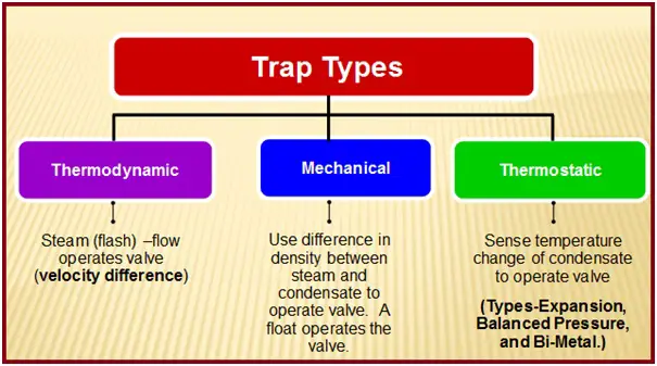
As classified by International Standard ISO 6704, there are three main types of Steam Traps as listed below:
Thermodynamic Steam Traps
Mechanical Steam Traps and
Thermostatic Steam Traps
Fig. 1 clearly explains the types of steam traps.
Fig. 1: Different types of steam traps
Thermodynamic Disc Steam Traps
Thermodynamic steam traps sense the velocity difference of entering fluids. When condensate enters the trap body, it moves slowly relative to the steam and is freely discharged. When flash or live steam moves across the underside of the disc, its velocity is much higher than water, and the high speed creates a pressure drop which closes the valve head. The valve stays shut until the control chamber steam pressure above the valve head drops, thereby allowing the valve to open.
Types: Thermodynamic Disc and Thermodynamic Piston.
Since air moves much faster than condensate; thermodynamic disc traps tend to close in the presence of air and are generally not suited for venting large amounts of air.
Thermodynamic Disc & Thermostatic steam traps: To handle air, a combination of thermodynamic disc traps and thermostatic air vents can be used.
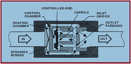
Operation of Disc Steam Trap
Disc traps operate as a function of velocity. Under normal operating conditions, condensate and air enter the trap and pass through an inlet orifice, a control chamber, and an insulating chamber (to isolate the trap against the effects of the environment).
Rated to operate 10 to 600 PSIG.
Small and lightweight therefore easy to install.
Frequently inspection required, not energy efficient because of short service life.
Not suitable when backpressure is high.
Fig. 2: Thermodynamic Disc Traps
Thermostatic Steam Traps
Thermostatic steam traps sense the temperature difference of entering fluids. The closure occurs when the fluid, typically hot condensate, has a temperature greater than or equal to a certain threshold value. The hot temperature causes a thermostatic element to move in such a manner that closes a valve. This temperature threshold value is below that of saturated steam.
Since air has a temperature significantly lower than steam, thermostatic traps are generally very good at venting large amounts of air. Thermostatic traps are rated to operate from 0 to 300 PSIG.
Fabricated with SS, CS, and cast iron housings.
Not effective when dirt and scale are present
Basic types: Expansion, Balanced Pressure, and Bi-Metal.
Expansion Type steam traps:
Expansion steam trap elements have an internal filling that expands and contracts with temperature change to actuate the valve, but the filling does not vaporize.
Wax elements are in a congealed state when cool, and expand when heated.
Petroleum-based elements are in a contracted liquid state when cool, and expand when heated
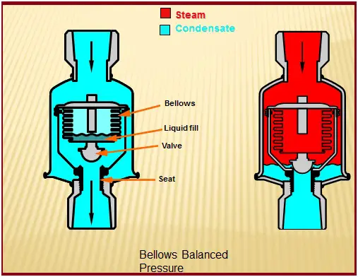
Balanced Pressure type steam traps:
Balanced Pressure steam trap elements have a filling which is a mixture of water and mineral spirits that generally vaporizes or condenses at near-to-steam temperature to actuate the valve.
Bi-Metal Steam Trap:
Bi-Metal steam trap elements are composed of two dissimilar metal strips bonded together so that temperature change causes a deflection in one direction or its opposite to actuate the valve.
Bellows balanced pressure type (Fig. 3) steam traps are suitable for High capacity whereas Wafer/Diaphragm balanced pressure is suitable for Low capacity. On the other hand, Bi-metallic steam traps can be used both for High or low capacity.
Fig. 3: Bellows Balanced pressure type steam trap
Mechanical Type Steam Trap
Mechanical steam traps are designed to open for more-dense fluids and close for less-dense fluids. There are two basic categories of mechanical steam traps that operate on the density principle:
Float type and
Bucket type
Within these categories, there are two types each of density traps: Lever Float, Free Float, Inverted Bucket, and Open Bucket.
Air is less dense than water. Hence, density steam traps tend to close in the presence of air and are generally not suited for venting large amounts of air. For this reason, density traps may contain a separate thermostatic air vent mechanism to handle significant amounts of air.
Float & Thermostatic,
Bucket & Thermostatic.
Float and Thermostatic Steam Traps
Float & Thermostatic steam traps combine the action of two principles: thermostatic and density. Each trap has its own discharge orifice. A valve with a ball float actuator drains condensate when the liquid reaches a predetermined level in the trap. When the flow of condensate diminishes’ the float drops, partially closing the valve to accommodate the flow rate.
At the top of the trap is a thermostatic element that opens to discharge all air and non-condensable gases as soon as they cause a small temperature drop within the trap.
Operate in between 0 to 250 PSIG pressure,
The condensate valve is located at the bottom and is subject to plugging when dirt and scale are present.
If the dirt particles prevent the valve from closing, steam energy will be wasted until the condition is detected and corrected.
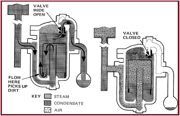
Inverted Bucket Steam Traps
Inverted bucket steam traps (Fig. 4) use an inverted bucket that is normally submerged and floats only when steam is present. The bucket sinks when the volume of condensate exceeds a predetermined liquid level. When the bucket sinks, the valve at the top opens.
Fig. 4: Inverted Bucket Type Steam Trap
Steam Trap Selection Guidelines
To get the maximum benefit from the steam traps, the selection of steam traps of the correct size and pressure is very important. The selection of steam traps shall be in accordance with the following:
Steam traps in low-pressure steam drip service shall be inverted bucket style, mechanical traps, or bimetallic thermostatic style traps.
Steam traps in medium-pressure steam drip service shall preferably be inverted bucket-style mechanical traps; alternatively, disc-type thermodynamic traps may be used.
Steam traps in high-pressure steam drip service shall preferably be inverted bucket-style mechanical traps.
Steam traps provided for steam turbine inlet drip service shall be thermodynamic piston-type traps.
A commonly accepted practice is to use float & thermostatic (F&T) steam traps for low-pressure steam systems up to 30 PSIG, and thermodynamic steam traps for steam pressures over 30 PSIG. Additionally, the following comparison table (table 1: Comparison of operating requirements for various types of steam traps) can be used as a guide for Steam Trap Selection:
Steam Trap Characteristic Features
Bi-Metallic
Inverted Bucket
Float & Thermostatic
Thermostatic wafer
Disc
Differential Condensate controller
Orifice
Operating Method
Irregular
Irregular
Continuous
Irregular
Irregular
Continuous
Continuous
Conservation of Energy
Excellent
Excellent
Good
Fair
Poor
Excellent
Poor
Resistance to Wear
Excellent
Excellent
Good
Fair
Poor
Excellent
Poor
Resistance against Corrosion
Excellent
Excellent
Good
Good
Excellent
Excellent
Good
Resistance to Hydraulic Shock
Excellent
Excellent
Poor
Poor
Excellent
Excellent
Good
Non-condensable gas Venting at steam temperature
No
Yes
No
No
No
Yes
Poor
Air venting at Low pressure
Not Recommended
Poor
Excellent
Good
Not Recommended
Excellent
Poor
Start-up air load handling
Excellent
fair
Excellent
Excellent
Poor
Excellent
Poor
Back pressure
Excellent
Excellent
Excellent
Excellent
Poor
Excellent
Poor
Resistance to freezing damage
Good
Good
Poor
Good
Good
Good
Excellent
Purge Ability
Good
Excellent
Fair
Good
Excellent
Excellent
Poor
Light load performance
Excellent
Excellent
Excellent
Excellent
Poor
Excellent
Poor
Response towards slugging
Delayed
Irregular
Immediate
Delayed
Delayed
Immediate
Poor
Dirt handling ability
Fair
Excellent
Poor
Fair
Poor
Excellent
Poor
The physical size of the Steam Trap
Small
Large
Large
Small
Small
Large
Small
Flash steam handling ability
Poor
Fair
Poor
Poor
Poor
Excellent
Poor
Mechanical Failure (Close or Open)
Open
Open
Closed
Either Open or Close
Open
Open
Not Applicable
Table 1: Comparison of operating requirements for various types of steam traps
International Codes and Standards for Steam Traps
International codes and standards that govern the steam trap design are listed below:
ISO 6552: 1980/ (BS 6023: 1981): Glossary of technical terms for automatic steam traps.
ISO 6553: 1980/CEN 26553: 1991 (Replaces BS 6024: 1981) Marking of automatic steam traps.
ISO 6554 1980/CEN 26554: 1991 (Replaces BS 6026: 1981) Face-to-face dimensions for a flanged automatic steam trap.
ISO 6704: 1982/CEN 26704: 1991 (Replaces BS 6022: 1983) Classification of automatic steam traps
ISO 6948:1981/ CEN 26948: 1991 (Replaces BS 6025: 1982) Production and performance characteristic tests for automatic steam traps.
ISO 7841: 1988/CEN 27841: 1991 (Replaces BS 6027: 1990) Methods for determination of steam loss of automatic steam traps.
ISO 7842: 1988/CEN 27842: 1991 (Replaces BS 6028: 1990) Methods for determination of discharge capacity of automatic steam traps.
ASME PTC39: Steam Traps.
ASTM F1139: Standard Specification for Steam Traps and Drains
FCI 85-1: Standard for Production Testing for Steam Traps.
FCI 69-1: Pressure Rating Standard for Steam Traps.
Sizing Steam Traps
Steam traps are not chosen based on the existing pipe size. Various factors are required to accurately size steam traps.
Condensate loads: Depending on the condensate load, the recommended size of equipment outlet piping is provided in Table 2
Safety factor to use: Safety factor should be selected based on experience. The values of the safety factor usually vary between 1.5 to 10.
Pressure differential: The steam trap should be able to open against the maximum pressure differential present in the system.
Maximum Allowable Pressure: The steam traps must be designed for the design pressure.
Maximum Condensate Load
Equipment Discharge Piping Size
Less than 200 kg/h
15 mm
200 – 500 kg/h
20 mm
0.5 – 1 MT/h
25 mm
1 – 2 MT/h
32 mm
2 – 3 MT/h
40 mm
3 – 5 MT/h
50 mm
Over 5 MT/h
65 – 100 mm
Table 2: Steam Trap Sizing with respect to Condensate Load
Causes of Steam Trap failure
Common Causes of failure of steam traps are:
Corrosion, due to the condition of the condensate. This can be countered by using particular materials of construction, and good feed-water conditioning.
Water hammer, often due to a lift after the steam trap, traps.
Dirt accumulates from a system where the water treatment compound is carried over from the boiler, or where pipe debris is allowed to interfere with trap operation.
The failure of a steam trap has severe implications for the steam system’s performance. If the steam trap fails in open condition, it will leak the steam and condensate completely causing increased steam consumption which in turn will add increased load to the boiler. However, when it fails in closed condition, neither steam nor condensation will pass through it. So the function of the steam trap will be halted which could lead to any of the following problems:
The presence of water (Condensate) in the steam system is a safety hazard.
So, it is essential to regularly monitor steam trap performance and fix the failed steam traps.
Steam Traps Performance Assessment
The performance of Steam Traps is assessed using any of the three methods mentioned below:
Visual Method-Visual inspection is performed using sight glasses.
Sound Method-Involves Distinguishing between Sound Frequencies using auditory equipment.
Temperature Methods-Works on temperature difference principle. However, Least Reliable method and hence normally not used.
Normally, preventive maintenance is performed for steam traps and the maintenance schedule depends on the pressure rating of the steam trap. As a thumb rule, high-pressure steam traps with a pressure rating greater than 250 psig should be tested daily. On the other hand, low-pressure steam traps with a pressure rating below 30 PSIG can be checked annually. Intermediate ones should be checked monthly. As a general rule, steam traps should be replaced after every three to four years.
Feature Requirements in Steam Traps
An Ideal steam trap should possess the following features for its best performance:
The steam trap should allow the condensate to pass and trap the steam.
Steam traps must be energy efficient and have negligible steam consumption. The steam trap must ensure that the steam space must be filled with clean dry steam. The type of steam trap will influence this.
Steam traps should possess good air venting capability. If air mixes with steam it will reduce the steam temperature.
It’s preferable that steam traps should not cause steam flashing.
Steam traps must have high Reliability. Sometimes, various external factors can cause unreliability in steam trap usage like
Knowing if a steam trap is working smoothly is important from an operational viewpoint. Various signs or indications are obtained in case steam traps are not working properly.
An abnormal increase in the boiler room temperature.
Frequent change in boiler operational pressure makes maintenance a challenge.
Steam trap inlet and outlet line reaching the same temperature.
Steam traps therefore must be maintained periodically to ensure the smooth working of the traps.
Steam Trap Maintenance
Steam trap maintenance philosophy usually consists of 3 stages:
Routine Maintenance: Cleaning and Checking at regular intervals to find any faults in it.
Replacing internal parts: Old internal parts of the steam trap should be replaced with new ones (Usually every 3 years) will ensure the undisturbed working of the steam trap assembly.
Replacing the Steam trap: If changing the internal parts does not resolve the problem, it is wise to replace the steam trap and install a new one.
How to perform the buckling analysis of Vacuum Piping
Buckling analysis for Vacuum Piping Systems is very important that every piping stress engineer should perform while analyzing Vacuum Piping. Vacuum piping analysis in the START-PROF software is analyzed according to the Russian Code GOST 32388-2013.
What is Vacuum Piping?
Vacuum piping is a piping system that operates at negative operating pressure. For example, if we remove all the air from a closed pipe then the pressure inside the pipe will be zero. This is called an absolute vacuum condition. The pipe thickness for such a condition must be designed for external pressure conditions, as well.
Setting Vacuum Pressure in START-PROF
The vacuum pressure in START-PROF software is specified by entering a negative operating pressure, the difference between internal absolute pressure and atmospheric pressure. Note that, The operating pressure that we set in START-PROF is not absolute pressure. It’s a relative pressure that indicates the difference between absolute internal and external pressures. So, If the internal absolute pressure is zero (absolute vacuum), then the operating pressure should be -0.1 MPa.
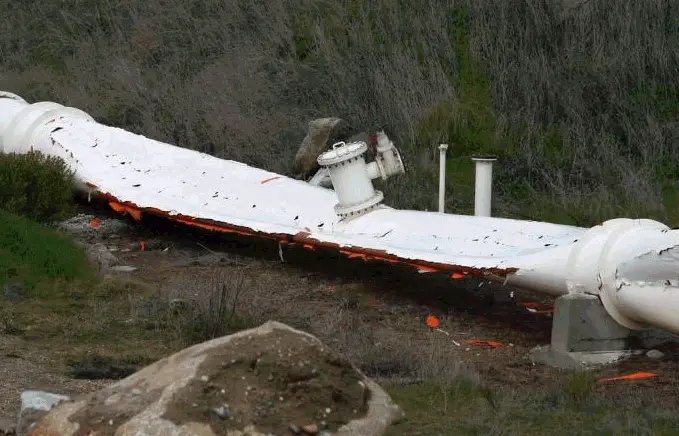
Fig. 1: Vacuum Failure due to Buckling
Features of vacuum piping
The main features of vacuum piping are as follows:
Pipes are shortened under external pressure instead of elongating.
Unbalanced axial expansion joints are shortened under external pressure instead of elongating.
The pipe wall buckling (stability loss) may happen under external pressure.
Buckling Analysis for vacuum Piping
After the START-PROF analysis is done the pipe wall buckling check table must be analyzed. Also, the additional check analysis could be done in Start-Elements. In this case, stability analysis for vacuum and strength under test pressure is checked.
If the buckling analysis is failed the wall thickness should be increased or stiffening rings must be added. The shape and distance between rings should be checked by analysis.
The buckling check of high-temperature piping is not possible because the method of analysis doesn’t consider the creep effect. See 14.1.1 GOST 32388-2013: This code applies to pipe operating under vacuum or external pressure, without metal creep. Wall temperature should not exceed 380 °С for carbon steel, 420 °С for low alloy steel, and 525 °С for austenitic steel.
Fig. 2: Vacuum Pipe, Bend, Reducer, and Tee Stability Analysis using START-PROF