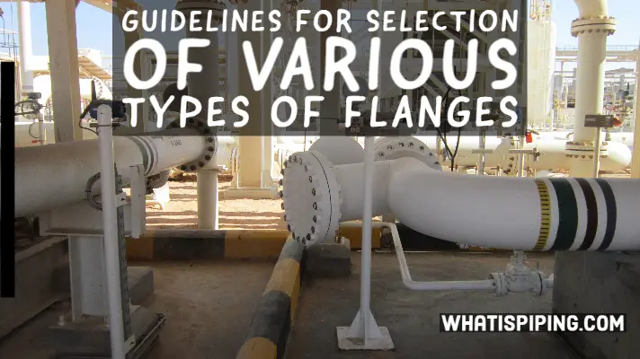
This article will provide a guideline for the selection of metallic pipe flanges and provides information on pressure-temperature ratings, dimensions, tolerances, materials, marking, and testing of piping flanges and flanged fittings in sizes NPS 1/2 to 48, and classes 150 to 2500 which can be used in conjunction with ASME B16.5, B16.47, B31.3, B31.4, and B31.8.
Pressure Temperature Rating of Pipe Flanges
The Pressure-Temperature ratings for the applicable materials listed in ASME B16.5, Table 1A shall be the maximum allowable working gage pressures at temperatures shown in Table 2 of the same standard. The basis for establishing ratings shall be the minimum wall thickness, which shall be in accordance with ASME B16.5, Annexure D. The material groupings are based on closely matched allowable and yield strength values.
Within each pressure class, the dimensions are held constant, irrespective of the material. Physical properties, and thereby the allowable stress values, of different materials, vary, so the pressure-temperature ratings within each pressure class vary with the material. For example, a class 600 forged carbon steel (ASTM A105) pipe flange is rated at 1270 PSIG at 400 °F, whereas a class 600 forged stainless steel (A182-F304) flange is rated at 995 PSIG at 400 °F.
Piping Flange Dimensional Standards
The following dimensional standards shall apply to metallic pipe flanges and bolthole patterns of non-metallic companion flanges:
- ASME B16.1, for integral cast iron piping flanges and blind flanges
- ASME B16.5, Classes 150, 300, 600, 900, and 1500 up to NPS 24, and class 2500 up to NPS 12. Class 400 carbon steel flanges shall not be used.
- Pipe Flanges larger than NPS 24 shall be specified in accordance with ASME B16.47. ASME B16.47 Series A for NPS 26 to NPS 60 in class 150 to 900 replaces these flange sizes in MSS SP-44. This is usually used in plants for mating certain valves.
- Series B supersedes API 605 in sizes NPS 26 to 60. Series B is used for pipelines and is restricted to pipe flanges used for joints.
- MSS SP-44 shall be used for steel pipeline flanges for sizes smaller than ASME B16.47 where the material grade is not listed in ASME B16.5
- Piping Flanges of unlisted materials and flanges not covered by the above standards shall be designed in accordance with ASME Section VIII Div 1, Appendix 2, and for blind flanges, in accordance with ASME Section VIII Div 1, Section UG-34
- Tolerances for pipe flanges shall be in accordance with ASME B16.5, section 7 for flanges up to NPS 24, and ASME B16.47 for flanges over NPS 24.
Pipe Flange Facings
Dimensions for flange facings shall be in accordance with ASME B16.5, Table 4 for flat face, raised face, and tongue and groove flanges, and Table 5 for ring joint flanges. These tables shall be used in conjunction with ASME B16.5, Figure 7.
Flat-face flanges, with full-face gaskets, shall be used when one or both of the mating pipe flanges in a joint are ASME B16.1. Class 125 gray cast iron, aluminum, or plastic, can be over-stressed by bearing against a raised face. Adapter rings may be necessary in some cases, to level off the surface, for mating equipment.
Raised face flanges shall be specified in ratings up to Class 600. These piping flanges are supplied with a 0.06-inch raised face, which is included in the minimum flange thickness. The finished height of the face shall be less than the nominal pipe wall thickness. Flanges in classes over 600 are supplied with a 0.25-inch raised face that is additional to the minimum flange thickness.
In ring-joint flanges, the thickness of the lap remaining after machining the ring groove shall not be less than the nominal wall thickness of the pipe used. Ring joint flanges for use with ASME B16.20 ring joint gaskets shall be used for:
- Piping Flanges in Class 900 and higher ratings
- Design temperatures in excess of 480 °C
- API 6A Type 6B flanges (wellhead piping)
- Hazardous fluid mediums
Tongue-and-groove facing, and male-and-female facing joints, shall not be used except in high-pressure service, or when it is necessary to match existing equipment.
Piping Flanges shall be finished in accordance with MSS SP-6, and ASME B46.1. Table I provides acceptable ranges of contact surface finishes for each type of gasket and service. The surface finishes shall be in Ra, Roughness average, expressed in micrometers, followed by micro-inches.
Pipe Flange roughness shall be judged by visual comparison to Ra standards using the GAR model S-22 Micro Finish Comparator.
Ring joint flanges shall have flat-bottom type grooves in accordance with ASME B16.20.
The bore of Welding Neck Flanges and Hub Design
Dimensions of welding end, bevel slopes, and bores shall be in accordance with ASME B16.5, Table 6, and Figures 8 to 14. Ratings of welding neck flanges shall be based upon their hubs at the welding end having thicknesses equal to that calculated for pipe having a 40 ksi specified minimum yield strength (SMYS). When the SMYS of the hub is less than that of the attached pipe, the minimum thickness of the hub at the welding end shall be at least equal to the product of the pipe wall thickness and the ratio, pipe to flange, of the specified minimum yield strengths. See MSS SP-44.
Mis-matches between pipe and flange shall be corrected during fabrication. Weldneck shall be tapered bored if specified in the purchase description. Pipe wall thickness shall be specified in the purchase description to ensure that the flange is bored within the specified tolerance.
Piping Flange Material Limitations
- Flanges and flanged fittings shall be castings, forgings, or plates.
- Bolting materials shall conform to ASME B16.5, Table 1B.
- The material for flanges in pipeline service shall be suitable for welding. The carbon equivalents shall match the pipe material.
Iron Flanges
Cast Iron Flanges: Gray cast iron flanges shall not be used for process piping within the battery limits of any plant. The only exception shall be for use in approved fire systems. The material shall be ASTM A 126, Class B.
Ductile Iron Flanges: Ductile iron flanges may be used, in proprietary systems, for example, plastic-lined steel piping, as backup flanges for lapped joints.
ASME B16.1 Class 125 and Class 250 cast iron flanges may be mated with ASME B16.5 Class 150 and 300 steel flanges respectively. However, care shall be exercised to ensure that a flat-faced cast iron flange shall mate only with a flat-faced steel flange, and vice versa.
Carbon Steel Pipe Flanges
- Carbon steel flanges shall not be used in services over 425 °C.
- General Service- The standard carbon steel material shall be ASTM A105. Standard material shall be used between minus 29 °C and 425 °C.
- Low-temperature Alloy Steel Flanges. Carbon steel flanges used for services below minus 29 °C, shall conform to the impact-testing requirements of ASME B31.3, ASTM A 350-LF2 shall be the standard material for this service.
Low and Intermediate Alloy Steel Piping Flanges
- Material for Low alloy steel flanges (11/4 Cr – 1/2 Mo) shall be ASTM A 182-F11. Material for intermediate alloy steel flanges (11/2 Cr – 5 Mo) shall be ASTM A 182-F5.
Stainless Steel and Non-ferrous Pipe Flanges
Usually, weld neck flanges shall match the metallurgy of the pipe in any material class. Austenitic stainless steels, however, may in certain cases be interchangeable. For example, type 347 and 321 stainless steels are compatible. Flanges that are double stamped, or double graded, and are so marked. For example, low carbon grades such as 304L, and 316L may be substituted, for the ‘straight’ grade, provided that the ‘L’ grade meets the physical requirements of the application.
When pipe material is forged, weld neck flanges shall be forged. When pipe material is not forged, material for weld neck flanges shall be subject to client approval.
Pipeline Service Flanges
- Flanges for pipeline service shall match SMYS, and carbon equivalency specified in ASME B31.4 and B31.8.
NACE Service Flanges
When an in-plant service has water and H2S concentrations above the limits specified in NACE MR0175, that service shall be considered as the NACE service. Flanges for use in the NACE service shall be in accordance with NACE MR0175 special requirements. The purchase description shall specify the ‘NACE service’.
High-Strength Material Flanges for Pipeline Service
Flange Types
The selection of appropriate joining methods varies with the required mechanical strength in the joint, from a minimum, as in slip-on connections, to a maximum, as in integral-type flanges that are cast, integrally forged, or butt-welded to the pipe.
Weldneck Flanges
- ASME B16.5 weld neck flanges with tapered hub and welding end shall be the primary selection for flanged joints in metallic piping systems of NPS 2 and larger. The individual material classes show the size range for any given service.
- Welding ends of weld neck flanges shall be in accordance with ASME B16.5, Figures 8 to 14.
Threaded Flanges
- When future material classes are generated, threaded flanges shall be added to material classes for threaded service, generally for mating equipment, and transitions between threaded and flanged piping.
- Threaded flanges may also be used for water and air service in pipe sizes NPS 6 and less and at a design temperature of 250 °F and below. Seal welding shall not be required.
- Threaded flanges shall be limited to size NPS 2 and smaller in hazardous service.
- Threaded flanges shall have taper-type threads and shall conform to ASME B1.20.1.
Socket weld Flanges
Socket weld flanges and socket weld-reducing flanges are added to material classes for mating equipment, where a union will be subject to external stresses; and transitions between socket weld and flanged piping.
Slip-on Flanges
Slip-on flanges cost less than welding neck flanges and require less accurate pipe cutting, but their strength is approximately 2/3 of weld neck flanges under internal pressure, and they have approximately 1/3 the fatigue life of weld neck flanges.
Slip-on flanges shall be welded at the front and back of the hub, but not on the sealing face.
Slip-on flanges and reducing slip-on flanges shall not be used in the following services:
- Severe cyclic conditions. See ASME B31.3, paragraph 300.2.
- Design temperatures above 230 °C, or where the corrosion allowance exceeds 3 mm
- ASME B16.5 Class 400 or higher rating
- Piping Flange sizes larger than NPS 24 unless stress calculations in accordance with ASME Section VIII Div 1, Appendix 2, with thermal and other external piping loads considered, show that the slip-on flanged joint will not be over-stressed.
- In hydrogen service with a hydrogen partial pressure above 690 kPa, flanges shall have a predrilled 3 mm diameter hole to vent the space between the pipe OD and the flange bore.
Lapped Joint Flanges
A lap joint is made up of a pair of stub ends, a pair of lap joint flanges used as a backup, and bolts and gaskets. These allow easy alignment of bolt holes and flanged joints.
The stub end shall match the material of the pipe. Stub ends for lapped joint flanges, if fabricated by welding, shall be made with full penetration welds.
Advantages are that lapped joints are an economical alternative to weld necks, and cost savings are large when the material is very expensive; dissimilar materials can be joined, provided galvanic corrosion does not occur; and spools can be rotated.
The disadvantage of this joint is that it is sensitive to external stress. Lapped joint flanges shall not be used in severe cyclic conditions.
Blind Flanges
- Blind flanges shall be used as end closures on flanged ends and valves unless end caps are specified in the design.
- Blind flanges are forgings and shall be manufactured to the same materials standards as other matching flanges.
- Blind flanges shall be of the same material as the weld necks, in all services. In corrosive atmospheres, stainless steel shall be used.
- Blind flanges shall not be drilled for connections, for example, drains and flushing, unless stress calculations in accordance with ASME Section VIII Div 1, Appendix 2 show that the flanges will not be overstressed.
Orifice Flanges
- Orifice flanges shall conform to this standard and ASME B16.36.
- Orifice flanges shall be weld neck flanges.
- Orifice flanges shall have jackscrews to facilitate the disassembly of the flanged joint during maintenance.
Other Standards
Other standards, for example, AWWA C207 for hub flanges, may be required for proper mating to equipment and shall be reviewed at the time of generation of a material class.
Information Required for Purchasing a Flange
The following shall be included in the purchase description for flanges:
- Type of flange
- Flange Rating
- Flange Dimensional standard
- Flange facing
- Contact surface finish
- Tolerances
- Material grade
- Additional material and testing requirements, if applicable
- Nominal size of the flange
- Wall thickness as defined by schedule, weight, or actual decimal wall
Marking of Flanges and Flanged Fittings
Flanges and flanged fittings shall be marked in accordance with MSS SP-25. The following shall be included in the marking:
- Pressure rating class
- ASME B16 designation
- Nominal pipe size
- The letter ‘R’ and the corresponding ring groove number for ring joint flanges
- The letters ‘PL’ shall precede the grade symbol followed by the material grade of the pipe
- Type of flange facing
- Schedule or wall thickness for weld-neck flanges
Some more ready references for you:
Flange Selection Guidelines
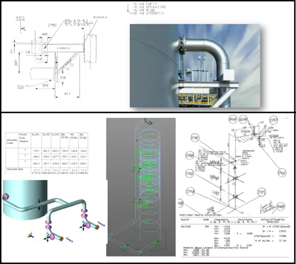
Pressure Equivalent Method in Caesar II
Flange leakage calculation ASME Section VIII in Caesar II
Flange leakage calculation NC 3658.3 method in Caesar II
Procedure for Flange Bolt Tightening of Various Sizes of Flanges