This Write-up/ Article guides to the proper installation of buried fiberglass piping systems. Designing a piping system to the latest engineering standards and techniques makes up for half of the job. The other half consists of the installation and the implementation of the design specifications. The requirements for installing buried fiberglass piping systems differ significantly from those of other conventional materials, for example from steel piping requirements.
GRP (glass-reinforced plastic) pipes, possibly built with mortar siliceous aggregates, are classified as “flexible” pipes, since they can work in a deflected condition, up to 5% of the diameter (long-term), fully in conformity with safety requirements.
Soil-Pipe System
The external loads (soil and traffic) above a GRP buried pipe cause a reduction of the vertical diameter and a consequent increase of the horizontal diameter (deflection).
This horizontal movement develops a passive soil resistance that enhances the pipe’s support by contrasting the deflection and increases its lift (fig.1). Please see the next picture.
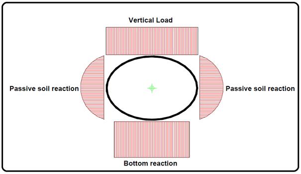
Thanks to the flexibility of the pipe, all of the external loads, such as soil and traffic that are loaded on the pipe, are sustained by a combination of the pipe’s stiffness and the stiffness of the soil surrounding the pipe.
Deflection
The amount of deflection depends on the soil load, the live load, the native soil’s characteristics, the pipe’s backfill material, the trench width, the filling, and on the pipe’s stiffness.
Buried fiberglass pipes generally accommodate 4-5% of long-term deformation without structural damage. An appropriate selection of the pipe’s stiffness class and its corresponding installation method allows for maintaining the pipe deflection within acceptable values.
Termonologies
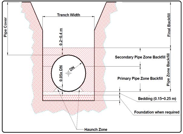
The figure (Fig. 2) below shows the meaning and the position of the elements that are used in this article, such as foundation, bed, primary backfilling, secondary backfilling, etc.
Following are listed a few terms and concepts that are used for soil description:
- fines = particles passing through the ASTM No. 200 sieve (with an opening of 0.075 mm), made of silt and clay
- fine-grained soils = soils where fine-grained particles are >50%
- coarse-grained soils = soils where fine-grained particles are <50%; made of sand and gravel
- sand = soil retained by the ASTM No.200 sieve but passing the ASTM No. 4 sieve (opening 4.5mm)
General Recommendations for GRP Pipe Installation
- The conditions of the different soils crossed by pipelines to be laid should be determined before installation.
- If this information is missing, is not available, or is incomplete, an investigation of these soils will have to be carried out.
- The result of this investigation not only will give the information that is necessary to define the suitable backfilling and compaction procedures but will also define possible areas of unsuitable materials, in order to minimize the use of selected material
- Fine-grained soils with medium/high plasticity, such as highly plastic clay and silts, or organic soils, generally are unsuitable for the backfilling area.
- The parameters that define the soil’s behavior have a determinant influence on the dimensioning formulae and on all of the verifications that are necessary for buried PRFV pipes.
In Situ Soils
It is important to determine the in situ soil conditions prior to the installation and even prior to pipeline design.
Data to be collected are:
- soil composition: the ratio between coarse-grained particles and fine-grained particles
- compaction degree (for soils with a predominance of coarse-grained particles) or cohesive strength (for fine-grained soils), that can be ascertained by means of penetration and shear tests
- groundwater conditions Investigations are addressed to evaluate the modulus of soil reaction (E’n) of the native soil at the pipe elevation and how it can affect the global reaction of the embedment.
Native soils with very low characteristics may reduce remarkably the stiffness of the embedment.
Since in most projects, the embedment materials and the rate of compaction are required to develop a modulus of soil reaction in the range of 7-14 Mpa, any normally consolidated and undisturbed native soil, is able to produce a modulus of soil reaction of the same magnitude or higher.
Embedment Materials
The material used for the bedding and for the backfilling of the pipe is classified according to its composition and its compaction degree
Soil Stiffness Categories
The soil Classification and the Soil Stiffness Categories are summarised in the following table (Fig. 3)
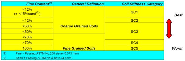
For further details regarding soil classification, please see ASTM-D2487.
- Most coarse-grained soils (SC1, SC2, and SC3) make acceptable beddings and pipe zone backfill materials.
- Fine-grained soils with medium to high plasticities, such as CH and MH, and organic soils such as OL, OH, and PT generally are proven to be unsuitable for pipe zone backfill materials. High plasticity and organic soils request special design considerations.
- The maximum grain size for backfill materials is 18 mm.
- Pipe zone backfill material must be compatible with the native trench so it will not wash away nor migrate into the native soil. Likewise, one must prevent the migration of the native soil into the pipe zone backfill area. Either of these events would result in a loss of side support for the pipe and consequently cause an excessive deflection.
- Migration can only occur if there is a movement of water in the pipe zone. When using incompatible materials, they will have to be separated with a filter cloth.
FRP Pipe Burial
Storage and Handling
When storing fiberglass pipes, prior to their assembly and burial, use at least three supports (wooden beams). Separate each row of pipes with supports. When a pipe is stored directly on the ground, ensure that the surface is smooth and rock free. Do not roll the pipe on the ground.
- Prior to installation, inspect each section of the pipe on both the internal and external surfaces in order to locate possible damages. Inspect also all joints, surfaces, and edges. Do not use damaged pipes without having first consulted our site supervisors.
- Only lift pipe sections with fabric straps.
Excavating the Trench
- On most construction sites it is best to execute the trench excavation, the pipe installation, and the backfilling consecutively in order to minimize logistic problems and reduce supervision costs.
- The bottom of the trench must be flat, continuous, smooth, and free from large rocks. The excavation of the trench bottom has to be deep enough to provide a minimum of 150 mm of bedding under the pipe.
- Trench construction will vary according to the different types of soil encountered (stable or unstable, granular or soft). In any case, the bottom of the trench must be flat and continuous.
Stable Trench Walls or Rock Trench
- Soils are considered stable only when it is possible to excavate the whole of the trench wall vertically, without the need for any supports or shores.
Unstable Trench Walls & Bottom
- With unstable soils, the trench wall may be excavated vertically with the insertion of sheet piles, bulkheads, or shores (installation method 1).
Installation in unstable soil-Shoring should preferably be done using a small thickness and it will have to be removed in concomitance with the backfill. Every backfill layer should be placed and compacted as the sheeting is being pulled out of equivalent height, in order to avoid the occurrence of voids beneath the sheeting and maintain the requested compaction. Refer Fig. 4
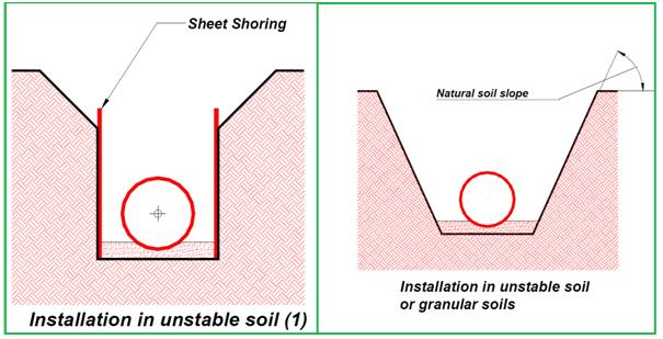
- The second installation method is done with the trench wall angle at the natural slope of the soil.
Granular Soil Trench
In this case, the trench walls will be at the natural slope (Fig. 4) of the native granular material.
Soft Soil Trench
When the native soil is composed of soils with high plasticity, very compressible, with a water content percentage on the dry soil weight exceeding 50%, as for soft clays, very melted mud, etc., the granular soil used for the laying bed and for the backfilling can be absorbed by the native soil. In this case, it is suitable to cover the bottom and the walls of the trench with a geotextile filter fabric, which has the function of separating the layers to prevent the granular materials composing the bed and the backfilling from being mixed or buried.
Trench Width
The trench width must be wide enough to guarantee a minimum distance between the pipe and the trench wall that can allow the backfilling compaction, according to the type of material used and the compacting method.
Furthermore, in case of excavation in soils that are not able to guarantee the side support requested by the project, the trench will have to be widened, according to the designer’s prescriptions, in order to stabilize the trench wall.
Suggested values for the trench width (L) are the following:
- DN ≤ 400 mm L= DN + 400 mm
- 400< DN ≤ 1000 mm L= DN + 600 mm
- DN > 1000 mm L= DN + 800 mm
The depth of the trench must be executed in such a way as to guarantee the dimensions of the bedding in accordance with the prescriptions of the following paragraphs. If the soil is not able to give the vertical support requested by the project, the trench will be deepened by 20cm or more, according to the prescriptions given by the designer, in order to obtain stabilization of the soil.
Moreover, should butt and strap joints be executed directly inside the trench, this must be widened and the trench bottom must be adequately lowered, allowing the lamination operations to be practical. These spaces will then be filled during the trench filling.
Multiple Pipes
If several parallel pipes are laid in the same trench, all of the pipes should have the same bottom level. The clear spacing between adjacent pipes must be at least 0.2 m, in any case not less than the diameter of the smaller pipe, and can be limited to 1 m.
The same spacing will be used for crossing pipes at different heights.
Trench Excavation Below Water Table
When an unstable soil condition is encountered that is caused by a water table, the bottom of the trench must be drained before laying the pipes. This can usually be accomplished by lowering the water table to approx. 30 cm below pipe level by means of pumps and stabilizing the bottom as previously described.
To minimize the soil dewatering, only a length of trench to place one or two sections of pipe should be opened and then be backfilled.
Foundation
The foundation shown in the above figures is required when the trench bottom is unstable, i.e. made of soils whose displacement, due to variation in stress or moisture content, is very high.
According to the different conditions of instability for the trench bottom, the installation contractor may require different types of foundations such as:
- stabilization and reclamation of the bottom, by removing an ulterior layer of at least 200 mm of depth and replacing it with stabilized gravel or sand, into which the unstable soil will not penetrate (ground capacity from 0.7 to 0.9 kg/cm2), that is able to redistribute the vertical pressures more regularly.
- pouring of lean concrete with a minimum depth of 150 mm (ground capacity from 0.5 to 0.7 kg/cm2);
- Foundation made with piles capped by concrete (ground capacity lower than 0.5 kg/cm2).
The above indications must be more closely followed as the diameter of the pipe to install is larger.
Bedding
- On the bottom of the trench, the bedding will be laid by using the materials that are described in the following sections. The bedding must have a thickness corresponding to 15% of the pipe’s diameter and in any case a minimum thickness of 150 mm that provides the pipe of uniform and continuous support over its entire length.
- The bedding surface must be even and recesses have to be projected in correspondence to every pipe joint. These recesses have to be backfilled after pipe installation and joining.
- The use of pea gravel, crushed stone, or sand as bedding material, with fine content not exceeding 12% is recommended. Fines are considered the materials, which pass through the ASTM 200 sieve. The dimensions for the bed materials’ grain diameter should not be greater than 20mm.
- The bed must be compacted until reaching 70% of its maximum density, before the pipe installation
- Different kinds of materials and compaction ratios can be authorized by the Designer.
Backfilling
Backfilling is divided into two areas
- Primary backfilling, which extends vertically from the culvert of the pipe up to 70% of the diameter; should preferably be composed of the same materials used for the bedding (maximum fines content 12% and maximum grain diameter 20mm), symmetrically laid by alternating layers of 20-25cm, compacted one by one, until reaching 70% of the maximum density for the specific material (90% Proctor Standard). Be sure that the areas under the pipe are filled up and compacted with accuracy, in order to grant valid support over an arc of at least 60%.
- Secondary backfilling, extending as far as 15 cm above the invert of the pipe; it can be made with the excavation resulting materials, even if it is preferable to use the same material as for the bed and the primary backfilling, symmetrically laid with alternating layers of 30-40 cm compacted one by one.
- Backfilling up to the ground level has to be completed with native material.
- During the backfilling one must avoid any pipe impact that may be caused by stones or by any other material that could damage it. If the backfilling is disposed of in a nonsymmetrical way or with non-uniform compaction, the alignment of the pipeline may be altered in such a way that it could influence the pipe’s seal.
Use of Different Materials
Materials that are different from the ones above described, but approved by the Designer, can be used for the composition of the laying bed and the backfilling, as long as the content of the granular materials (retained by the ASTM 200 sieve) is greater than 30% and the liquid limit is lower than 50%.
Please take note that by increasing the fine content of the material, the energy required for the tamping of the material itself will increase. Furthermore, it’s useful to intensify quality controls and check the right laying of the backfilling.
FRP Pipe Installation
To install the pipes, the following procedure can be used, as a function of the type of joint and of the pipe diameter:
a) for any type of joint and diameter: lay and align the pipe bars on the bed that has been previously prepared, and perform the junctions inside the trench.
b) for pipes with joints that guarantee axial continuity:
- lay on the bed two or three bars, previously joined outside the trench, in order to reduce the number of junctions to be performed inside the trench.
- align and join the pipe bars alongside the trench or above it, by using ties; lower the jointed pipeline into the trench by using several hoisting equipment being careful not to cause excessive deformations; this method can be used for small diameters only.
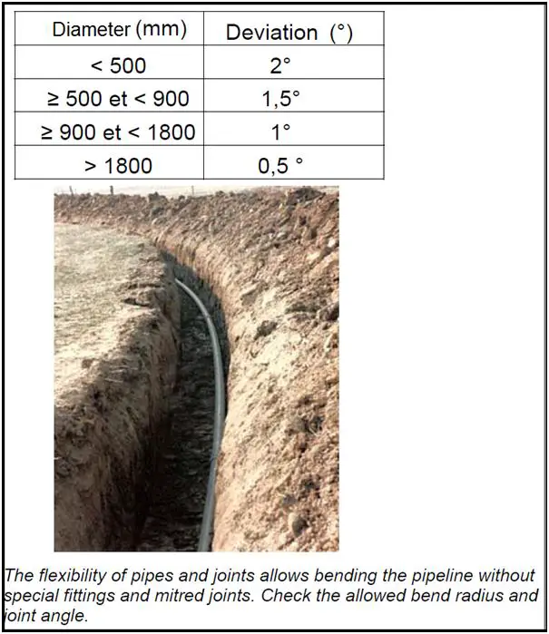
In the case of bell/spigot or socket joints with o-rings, please verify that the angles that have been given do not exceed those allowed. Refer Fig. 5
Typical Compaction Methods
Compaction can be made by using a pulse compactor or other suitable systems. In case the backfill is composed of sand, the compaction can be obtained by saturation. If this method is used, it is necessary to verify the draining capacities of both the bed of the trench and of the native soil; if necessary provide suitable drainage systems and use an adequate quantity of water, in order to prevent the pipe from floating.
The laying trench should be filled up as soon as possible, as far as ground level or for a height of 1.3 diameters, in order to prevent the pipe from floating, in case of laying in presence of a water table or in little draining soils.
Modulus of Soil Reaction
Pipes are generally checked in the actual working conditions, by using a certain Modulus of Soil Reaction, which becomes one of the design’s mandatory prescriptions, together with the:
- material to be used for embedment
- compaction degree (soil density) and
- trench width.
If the installer is given the possibility to change one of the above parameters, the following table is shown the Modulus of Soil Reaction that can be achieved with different materials and soil densities.
Installation Control
Deflection checks must be carried out when the first installed pipes have been backfilled. Further periodical checks must be done throughout the entire project.
Where it is practical, measurement has to be taken of the density of the pipe zone material primarily compacted to ensure compliance with the design assumptions.
Concrete Block Connection
When connecting with concrete blocks and walls, it is necessary to follow some prescriptions, in order to avoid damage to the pipes, due to these two phenomena;
- high differential settlements between manufactured product and pipe, due to the considerable weight of the concrete works in comparison with the relatively light PRFV pipes; this phenomenon is particularly clear if the concrete work, or a part of it, is made after having already laid and buried the pipeline, and it can cause high longitudinal shear and flexural stresses to the pipe;
- Very sudden passage of the transversal section of the pipe from a deformed configuration due to the normal deflection, to an un-deformed circular configuration in the area, filled up with concrete; this phenomenon only occurs to a short section, at the end of the concrete block, due to a complex stress condition.
In both cases, the larger the pipe diameter, the more evident the phenomenon, and it is necessary to take care that the deflection is minimum near the manufactured product.
It is suggested to take the following precautions, according to the actual working conditions
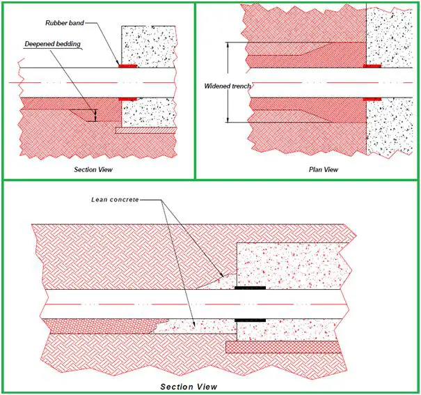
- in correspondence to the connections with the concrete, always wrap the pipe with a rubber sheet, (Fig. 6) 100/200 mm large and 10/30 mm thick, in order to reduce strain concentrations:
- design and verify with accuracy the concrete works and thrust blocks, with particular care to the settlement check
- improve the stiffness of the backfilling near the manufactured products, by widening and deepening the trench (Fig. 6) and filling it up with well-compacted granular materials; the variation of the trench section should take place gradually, over a length of about two diameters.
As an alternative, backfill the pipe with lean concrete (70 kg/mc) for a length of about one diameter (Fig. 6), near the connection without using form works, this allows the lean concrete to flow, following the natural angle of friction
- create a strong PRFV ribbing on the pipe close to the connection with the concrete manufactured product;
- If you can’t keep the differential settlement within an acceptable limit, one should use a flexible joint (bell/spigot or socket joint), which allows rotation of 1-2° just out of the concrete manufacture (generally it is not necessary for diameters up to 300 mm).
Online Video Course of FRP/GRP/GRE Pipeline Stress Analysis using Caesar II
If you are interested in learning FRP/GRE/GRP Piping Stress Analysis using Caesar II software, you can have a look at the following online video course