
Nozzle loads are the forces and moments that the piping system exerts on the equipment nozzles. One of the important qualification requirements while stress analysis of a piping system is to keep these loads and moments within a given allowable limit which is known as Nozzle load allowable values. Nozzle loads are basically sets of three forces and three moments with respect to three axes. These loads and moments are generated in the nozzle connection due to various factors like Pipe Weight, Design Pressure, Thermal movement, Occasional effects, etc.
One of the major difficulties piping stress engineers face while analyzing any piping system is to keep piping side loads or external loads (forces and moments are combinedly mentioned as loads) on equipment nozzle connection within allowable limits. All equipment to which the piping system is connected is categorized into two groups.
- a) Static Equipment and
- b) Rotary Equipment.
Nozzle Loads for Static Equipment
Most of the prevailing EPC organizations follow a project-specific table as allowable values for static equipment (made of steel, ferrous material) like pressure vessels (Columns, Horizontal vessels, Drums, Reactors, Filters, Scrubbers, and sometimes Tanks which are not within API 650 scope, etc) and shell and tube heat exchangers or similar equipment.
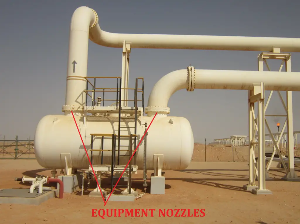
The allowable nozzle load table is generated based on the following two-parameter:
- the nozzle diameter and
- flange rating.
In some organizations, the table value is multiplied with some factors (normally 0.75) while checking nozzle loads for shell and tube heat exchangers.

Normally the mechanical department includes this load table in the equipment purchase requisition and sends it to the equipment vendor while bidding. It is clearly indicated that the nozzle connections must be designed to resist the table values. The equipment vendor reproduces the values in the equipment general arrangement drawing to avoid any confusion at a later stage.
For cases, where the static equipment does not fall into the types mentioned in the above criteria the nozzle loads have to be obtained from the equipment vendor or from some ASME B31.3 code specified standards. A few of such type of equipment and nozzle connection is listed below for your reference:
Jacketed nozzles connected to Normal pressure vessels:
Loads are to be obtained from the manufacturer, in case the piping side load is more than allowable loads have to be forwarded to the vendor for FEA/vendor acceptance.
Jacketed nozzles connected to Jacketed pressure vessels:
Loads are to be obtained from the manufacturer, in case the piping side load is more than allowable loads have to be forwarded to the vendor for FEA/vendor acceptance.
Pressure vessels made of nonferrous (Aluminium is more common) materials:
Loads are to be obtained from the equipment vendor.
Nozzles connected to Air Fin Fan Cooler:
Loads are mentioned in API 661, discuss with the vendor (check internal project specification) if any factor is to be used (Normally a factor of 2 or 3 is used in some organizations).
Nozzles connected to Plate Fin Heat Exchanger:
Refer to API 662 for nozzle loads (There are 2 tables in the standard depending on fluid service (normal service and severe service), check carefully which table to be used)
Tangential nozzles connected to Pressure Vessels:
Loads have to be taken from the manufacturer.
Nozzles whose axis is not perpendicular to the Vessel axis:
Obtain allowable loads from the vendor.
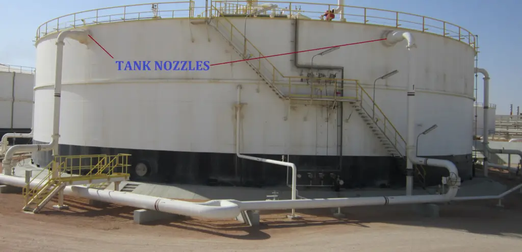
Nozzles connected to API Tanks with diameters more than 36 meters:
Refer to API 650 for nozzle loads (No standard table is provided for load values, you have to determine the loads from equations.)
Nozzles connected to Fired Heaters:
Refer to API 560 for allowable nozzle loads. Sometimes a factor of 2 or 3 is used for multiplying the table values. Refer to project specifications for the same or discuss it with the vendor.
Nozzles connected to Miscellaneous Equipment (Cold Box, Flaker system, Packaged items, Spherical Equipment, Cooling Tower, etc): Arrange limiting loads from Vendor.
Nozzle Loads for Rotary Equipment
Normally rotary equipment is designed based on some code-specified standards and accordingly, the limiting loads have to be taken from respective standards. Some such commonly used equipment are mentioned below:
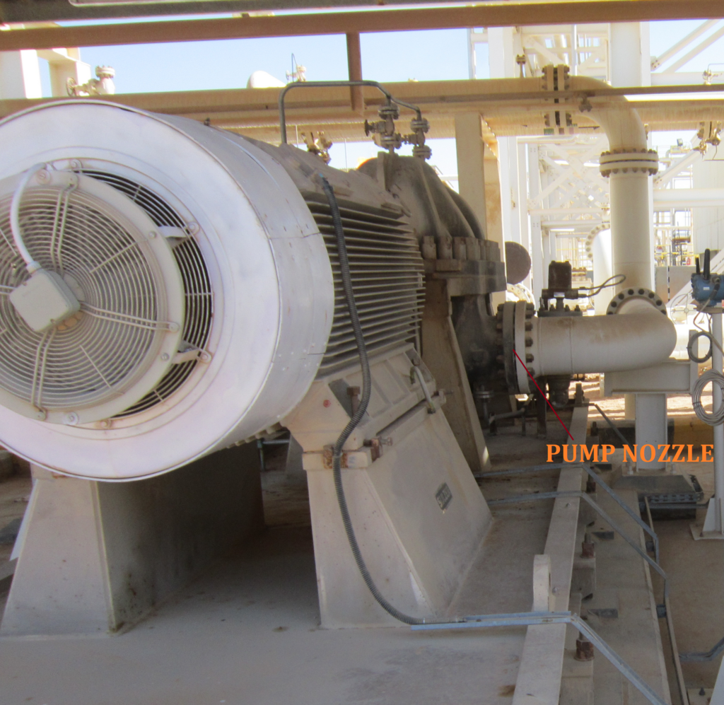
Nozzle Loads for Centrifugal Pumps
For pumps that are designed based on API standards, allowable loads have to be taken from API 610 (If loads are more than allowable values as specified in table 5 of the standard, perform Appendix P). Allowable load values up to nozzle size 16 inch is provided in the table. For higher sizes, the ANSI standard is used. If the pumps are not designed as per API standards (nowadays non API pumps are most frequently used due to its lower costs) obtain loads from the vendor. Sometimes ANSI/HI 9.6.2 is used for nozzle loads in absence of data.
Positive displacement (Screw pumps, gear pumps, etc) pumps:
Use API 676 for allowable nozzle loads. Loads can be taken from the vendor.
Reciprocating Pumps/Compressors:
Obtain the allowable nozzle loads from the vendor.
Centrifugal Compressors:
Use API 617 for equipment nozzle loads. Note that combined analysis must be performed for the proper functioning of the compressor. Sometimes the vendor permits more loads so discuss with them.
Steam Turbine:
Refer to NEMA SM23 or API 612 for allowable nozzle loads. Don’t forget to perform combined nozzle load checking. Sometimes the vendor permits more loads so discuss with them.
Positive displacement compressors:
Refer to API 619 or manufacturer allowable loads.
Gas Turbine: Loads are to be obtained from the manufacturer.
Means for Reducing Nozzle Loads
Now if the nozzle load on equipment is found to be more than the allowable values as specified above, first try to get a feel of the reason for the increased load and then try to apply any of the following alternatives to reduce the nozzle loads:
- Try to reduce the nozzle load by adding additional flexibility in the piping system (Could be followed if the load is arising because of less flexibility)
- If the load is due to the weight of the piping system, provide additional support.
- Try to direct the thermal expansion away from the equipment by providing proper restraints (guide or directional anchors).
- If the load is more because of friction then try to use PTFE/graphite/Mirror polished SS plates to reduce frictional loads.
- In extreme situations expansion joint or cold spring (normally not preferred) can be applied.
- Sometimes hot modulus of elasticity can be used to calculate equipment nozzle loads.
Even after all trial and error if it is not possible to reduce the loads within allowable limits then forward the actual load values (increased by at least 20% if all piping data is not final) to the vendor for FEA analysis and their acceptance. Click here to know 10 important points related to pressure vessel nozzle load tables.
Sir,
How to use Nozzle Limit Check in caesar?
Please explain to me.
Thank you.
I deal with skid installed piping and equipments. In this case Skid allowable nozzle loads are required. How can I use CAESAR software to calculate allowable TP (Skid inlet/outlet nozzles) loads?? Is there any simplified calculation to extract loads before CAESAR analysis??