Piping Stress Analysis is the scientific or engineering study of all the stresses generated in a piping system. Now from where this stress comes? From the mathematical definition of stress, we all know that Stress is the Reaction Force per unit area. So, this clarifies that piping stresses are generated because of some kind of loads or forces in the piping system. The forces the piping system faces are categorized into two distinct groups.
Primary loads and
Secondary loads.
In this article, we will study the differences between these two types of load categories.
What is a Primary Load in a Piping System?
Normally Force driven loads are called Primary loads. These loads are generated due to gravitational forces, internal or external fluid pressure, spring forces, relief valve discharge, pressure waves during water hammer or surge effects, etc. Hence, Primary loads originated due to some kind of force acting on the piping system. A large value of Primary loads creates plastic deformation leading to catastrophic failure. In a catastrophic failure, each individual crystal is subjected to stresses that the body can not withstand and causes rupture.
What is a Secondary Load in a Piping System?
Secondary loads are usually displacement-driven loads. These loads are generated due to some kind of displacements imposed in the piping system, for example, thermal expansion, settlement, anchor movement, vibration, etc. Most of the time (not always, for example, tank settlement) these are cyclic in nature. Such kind of loads normally results in fatigue failure. In fatigue failure, the grains collectively fail because of incremental damage done by each cycle.
Primary Load vs Secondary Load
Primary Loads vs Secondary Loads
The following table lists the major differences between primary and secondary loads.
Sr No
Parameter
Primary Loads
Secondary Loads
1
Definition
Primary loads are Force Driven
Secondary loads are Displacement Driven
2
Self-Limiting Nature
Primary loads are not self-limiting. Once plastic deformation begins it continues until force equilibrium is achieved through changes in boundary conditions or by material strain hardening or until the element fails catastrophically.
Secondary loads tend to dissipate as the system deforms through yielding and hence such loads are self-limiting.
3
Cyclic Nature
Primary loads are Non-Cyclic in nature
Secondary loads are Cyclic (except Settlement)
4
Failure Modes
Catastrophic, Quick, and Sudden. Failure by primary loads is based on one or more failure theories like Von Mises, Tresca, or Rankine Theory.
Fatigue and non-catastrophic in nature. Failure is not sudden and time taking.
5
Failure due to a single application of load
A single application of excessive primary load (example pressure) may cause design failure by gross plastic deformation and rupture
Failure never happens because of a single application of load. Normally it takes a high number of load applications for failure to occur.
6
Allowable Stress Values as per Process Piping Code
Allowable stress values for stresses generated by primary loads (Primary Stresses) are normally less and limited by Sy (Yield Stress) at maximum temperature.
Allowable stress values for stresses generated by secondary loads (Secondary Stresses) are normally more than Sy.
7
Load Duration
Few primary loads like Weight are always present in the piping system throughout the plant life.
Secondary loads are normally present only when the plant is operating.
Table listing differences between Primary and Secondary Loads
The knowledge of both stress and strain is very important in design as their relationship to each other defines the mechanical properties of a material. But which comes first between Stress and Strain is really a very confusing question to many. Whenever a force is applied to a body, Stress, and Strain both are believed to occur. But which one comes first? Let’s try to understand the same from the basics.
What is Stress?
Whenever a force is applied to a body from outside (external forces), its first tendency is to resist that force. So, the body will generate an internal resistance force that will resist the external force to create any damage (deformation). This internal resistance force per unit area (cross-sectional area on which Force acts) is called stress and is denoted by
Stress (Ϭ)= -F/A
What is Strain?
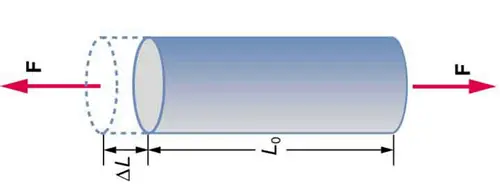
Refer to the image below (Fig. 1). When the pipe is pulled using a Force F, the pipe elongates i.e deformed from its original length L0
Fig. 1: Force and Change in Length
The strain is the geometric quantity that measures the deformation of the above pipe. The ratio of this elongation (∆L, change in length) with respect to the original length (L0) is known as Strain and expressed as
Strain (δ) =∆L/L0
Which comes first: Strain or Stress?
From the above paragraphs, it is clear that for the generation of Stress or Strain, the main contributing factor is the Force, F. So force is the cause. And Once force is applied, it tries to deform the body instantaneously. So obviously, deformation or change in length will come first. This deformation can be measured using Strain gauges. Because once deformation or damage tends to appear, then only internal resistance force will be created and will try to resist that change. So, there has to be deformation first for the creation of stress. Actually, stress is a derived value, it’s only a mathematical term. You can not see or measure it. Similar to Strain gauges there is no instrument where stress can be measured. It is always calculated.
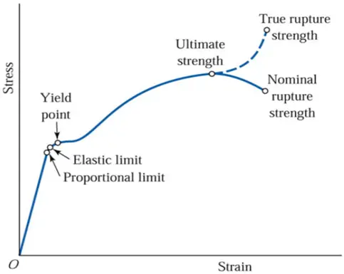
The same philosophy can be easily understood from the Stress-Strain curve, as well. For generating a curve, the standard practice is to keep the independent parameter on X-Axis and the Dependent one on Y-Axis. Now, look at the image below (Fig. 2) showing the stress-strain curve.
Fig. 2: Stress-Strain Diagram
The Strain is on the X-axis and Stress is on the Y-Axis. Hence, It is clear that Stress is dependent on Strain.
Again, the above definitions of Stress and Strain are provided based on two assumptions.
The cross-sectional area (A) is considered constant throughout.
The original length (L0) is considered constant.
So, Now we defined the above; Stress =Force/Area and Strain=Change in length/original length.
According to the above assumption, both Area and Original Length is constant. So the above Stress-Strain curve can be considered as a Force vs deformation curve. Which means Force is creating the deformation.
So from the above discussions, it is clear that Strain comes first, and then Stress is generated.
Expert opinion says that among all piping design issues, 20% of issues are directly related to the support design and the other 20% are indirectly related. So overall 40% of the problems in the piping design are related to pipe support. Hence pipe support design is one of the most important aspects of piping design and should be considered an integral part of it. Spring hangers or pipe hangers are very useful piping supports for Critical piping systems. This article will provide some useful insights into Spring Hanger Selection Procedure. Towards the end of the article, Link for a Recorded Webinar on the above Subject by Technology major, Bentley is provided for further insight.
What are the different types of pipe supports?
There are different types of supports that are used in Piping Design. Depending upon the application, those can be roughly divided into load-bearing supports, restraints, and vibration absorbers.
Load bearing and hanger supports are used to carry the weight of the piping system. Simple resting support and hangers.
Restraints restrict the movements due to thermal and dynamic loads acting in the piping system. Guides, line stops, and anchors fall under this category.
Guide restricts lateral and vertical movements and allows axial movements, whereas line stops (or axial stops) restrict axial and vertical movements and allows lateral movements.
Pipe Anchor support prevents all movements in all directions.
Vibration absorbers like Snubbers, Sway braces, Hold Down, etc restrict the movements due to vibration caused by wind, earthquake, fluid flow, and other dynamic loadings
All the above support may be used as single support or in a combination.
Requirements for Spring Hanger Supports
The most economical and efficient way to support the piping is to simply rest the piping on a rigid support structure. Being supported with rigid supports, the pipe will either generate a potentially huge upward force when the pipe expands downward or leave the support inactive i.e. lifting off when the pipe moves upwards. This is the case where stress engineers suggest using spring hanger support
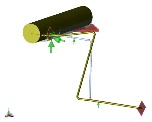
Whenever rigid supports in the system are not taking load due to their thermal movement or rigid support may cause an overloading effect to equipment connection, spring hanger pipe supports are used to share some of the loads and to keep the piping system safe without affecting expansion stresses. We can understand this scenario with a simple example here. Refer to Fig. 1. This piping system of a pipe size of 6 inches (150 NB) is connected to a nozzle on a horizontal vessel. To sustain the weight of the system, we have added two resting support in between and an anchor at the end.
Fig. 1: Typical Piping System explaining the requirement for Spring Hangers
Now the total weight of the piping system is shared by four supports, an Equipment nozzle, two resting support, and an anchor.
Let’s assume that this piping is operating at a temperature of 200 deg C and a pressure of 4 bar. Due to thermal expansion, the vertical piping leg expanded in the vertically up direction (as it won’t expand in a downwards direction due to the support at node 20), and support at node 50 near the nozzle lifts off. In this case, the total piping weight is now shared by 3 supports only, the Equipment nozzle, and only 1 resting support (Node 20) as the other one (Node 50) is lifting off and anchored. This may cause overloading of the equipment nozzle.
In such a situation, Spring hanger pipe support comes into the picture. The support at node 50 can be replaced with a spring hanger support to take piping load during operating conditions without affecting expansion stresses too much. In simple words, We can say that the spring hanger is taking the weight of the piping system allowing thermal movements.
Functions of a Spring Hanger Pipe Support
Hence, the main objectives or functions of the hanger supports are as follows:
To provide necessary weight support to balance the piping system during the complete operating cycle.
To permit the operational movement of the pipe as it goes from cold to hot or vice versa.
It does not cause excessive expansion stresses in the pipe as the spring load changes from cold to hot or vice versa.
The selection of the appropriate type of hanger support for any given application is governed by the individual piping configuration and job requirements.
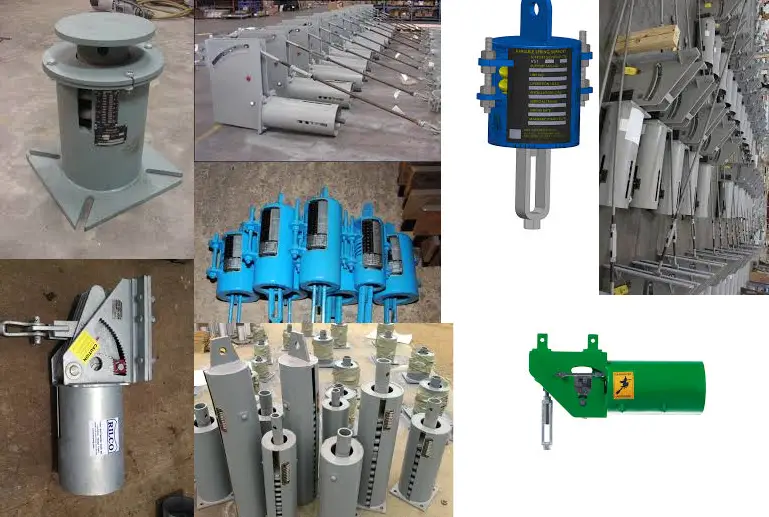
Types of Spring Supports
There are two types of spring hanger supports available in the market; Variable Spring Hanger and Constant Spring Hanger.
Variable Spring Hanger Support
In variable spring hangers, supporting force varies with piping displacements. Piping vertical thermal displacements cause extension or compression of the spring which changes the actual support effect of the spring. There is variation in supporting force as the load varies from cold to hot conditions. This variation should not exceed a certain limit.
The arrangement for these is very simple with single or series of springs attached to piping and both piping and spring are on the same axis. These springs can be installed in small spaces, and are relatively inexpensive, but load varies so this can be a drawback with large displacements.
Fig. 2: Various Types of Spring Hangers
Constant Spring Hanger Support
Unlike variable hanger support, Constant Spring Hanger support provides constant supporting force throughout the displacement range. Constant hanger supports are provided with lever and cam arrangement. Changes in piping displacement are balanced by the moment produced due to the cam and lever.
As a result, the resisting force provided by this spring support is independent of position during its travel and approximately constant throughout its range. Typically, the variation of the active and reactive forces is very small.
Constant Effort spring shall be selected where you have excessive vertical movements, where it is necessary to restrict the transfer of load from the displacing spring adjacent terminal of equipment, or where the Spring variability is exceeded.
These are more expensive supports but are ideal for conditions where pipe movements are large and the sensitivity of equipment is important. They also have different types for different applications
Variable spring hanger support terminologies
Variable support is essentially a spring, or series of springs, in a container used to support piping loads above or below piping. As already mentioned, in variable spring hangers, supporting load varies with piping displacement and there is load variation from installed condition to operating condition.
When the installed load is applied, the spring is compressed by some distance as per spring stiffness. This is also called a Cold Preset.
Piping thermal displacement produces a deflection in the spring which further adds differential load on the spring. Depending upon the direction of the thermal displacement, the spring may further compress Or expand.
If the pipe moves upwards the spring will expand to subtract differential load from the cold preset load to get operating or hot load. On the other hand, If the pipe moves downwards spring will further compress to add a differential load with the cold preset load to get the operating load.
This differential load is nothing but the difference between the installed load and operating load i.e. Cold load and hot load. This differential load is also a function of spring deflection and can be calculated as Spring stiffness x Thermal displacement
Hot load – Cold Load = Spring Stiffness x thermal movement
This can also be written as
Cold Load (CL) = Hot Load (HL) +/- Spring rate x thermal displacement.
If the pipe moves upwards, the cold load is more than the hot load and if the pipe moves downwards cold load is less than the hot load.
In order to minimize the stress variation, the differential load for given variable spring support is limited to a maximum of 25% percent of the operating load or hot load as per industry standards.
We can write this in mathematical form as
Variation = (HL – CL) / HL <25 %, Which is also written as Variation = Spring rate x thermal displacement / HL <25 %
This means that, regardless of the pipe movement, the spring will carry no more than 125% and no less than 75% of the properly balanced portion of the load.
Rigid hanger criteria
We often come along with this terminology during spring hanger selection.
Consider a case in which a spring hanger is provided exactly near the equipment nozzle and there is a requirement to consider this extra weight for the nozzle flange and hardware.
In such a case, the hanger is released at anchor. In this particular direction, support is removed for the hanger selection procedure and there will be more weight used in the selection process for spring to simulate disconnecting equipment
The spring is designed for higher weight and has the capacity to carry this extra weight of equipment
Hot and cold load design
Loads of a spring hanger change throughout the operating cycle. By setting the pre-operation cold condition load at a certain level, we can predict the load at operating conditions based on the expected vertical displacement. And load variation is calculated as spring rate times the vertical displacement.
The load that balances the weight of the portion of the supported piping is called the balanced load.
Ideally, we like to set the balanced load at the midway of the operating cycle, so we can shift one-half of the load variation to the cold condition and the other half to the hot condition.
Practically this is not possible as the piping system is either hot-balanced or cold-balanced.
Hot balance vs Cold balance
In hot load design, the balanced load i.e. weight of supported piping is selected as hot load whereas, in cold load design, it is selected as cold load.
Hot balancesets the hanger in such a way that the spring load at hot operating conditions equals the balanced load. Theoretically, this is the preferred approach because it minimizes load and sustained stress at the most important hot condition.
This is a must used for piping operating at creep range, where creep damage depends largely on sustained stress at operating condition
Cold balancesets the hanger force to balance the weight load in cold conditions. This leads to some unbalanced force at the operating conditions when the piping is at hot operating conditions. Theoretically, this approach is not as good as the hot balance option.
Those field engineers who represent large types of machinery such as compressors, tanks, and turbines operating at low to moderate temperatures, insist to use cold balance springs on the piping systems attached to their equipment
This often creates arguments between the machinery/site engineer and the piping stress engineer to use spring load design.
Cold balance is very popular in the field as during the installation process, the spring cold load is in balance with the weight of the portion of the piping being supported and this may resolve alignment issues for equipment nozzles
but somehow this does not yet capture the attention of stress engineers
If we know the rationale behind the equipment engineer’s insistence, the job can be better handled avoiding friction between the design and installation team
Spring hanger Support Manufacturer
There are different spring hanger manufacturers available in the market like Lisega, Piping Technology, and Products, Anvil, Carpenter & Patterson, etc. and the stress engineer has to select a spring hanger manufacturer as per project specifications.
In AutoPIPE, one can select spring hangers from 27 different spring hanger manufacturers while Caesar II provides 30 different manufacturers in their Database.
Recorded Webinar on Spring hanger Selection Procedure using AutoPipe
Bentley conducted a webinar for a detailed explanation of the Spring Hanger Selection Procedure using AutoPipe software on Wednesday, April 29, 2020, at 10:00 AM India Standard Time. If you need clarification regarding spring hangers, Simply Click Here to Access the Recording of the Webinar.
The above webinar briefly explained the following points:
Need for Spring Hanger Support in piping
Standard Hanger Selection Procedures – Hot load and cold load
Spring hanger selection and analysis in AutoPIPE
Online Video Courses on Piping Support
To learn more about piping support design and engineering you can opt for the following video course.
Developed and maintained by ASME, ASME B31.4 is the design code for pipelines transporting liquids and slurries between facilities, production, and storage fields, plants, and terminals, and within terminals and pumping, regulating, and metering stations associated with liquid pipeline systems.
What is ASME B31.8?
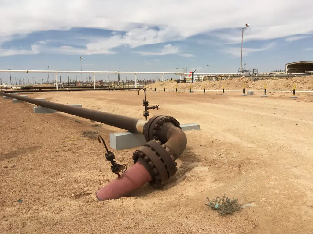
ASME B31.8 is the design code for pipelines for Gas Transmission and Distribution Piping Systems. This means this code provides design guidelines for piping transporting products that are predominately gas between sources and terminals, including compressor, regulating, and metering stations, and gas gathering pipelines.
Fig. 1: A Typical Pipeline
ASME B31.4 vs ASME B31.8
So, both the codes, ASME B31.4 and ASME B31.8 are pipeline design codes that cover the design, fabrication, installation, inspection, and testing of pipeline facilities. But, ASME B31.4 deals with pipelines transporting liquids and slurries whereas ASME B31.8 deals with gas transmission and distribution. Now the question is whether both can be used interchangeably and if not then what are the differences between ASME B31.8 and ASME B31.4?
The liquid is incompressible while gas can be easily compressed, So the behavior of both fluids is different under pressure and temperature conditions. Hence, the ASME B31 committee devised two different codes for liquid and gas pipelines.
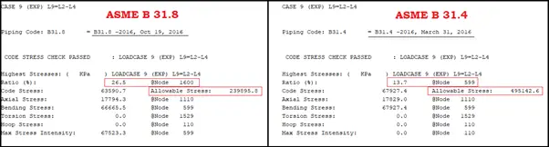
Refer to the following image (Fig. 2) which lists the expansion stress range results for the same stress system with the same parameters analyzed in Caesar II-2018.
Fig. 2: Expansion Stress output for the same system based on ASME B31.8 and ASME B31.4
Results show that the expansion stress ratio for the system is around double (26.5%) for code ASME B31.8 as compared to ASME 31.4 (13.7%) which means code ASME B31.8 is more stringent from stress analysis consideration.
In this article, we will list some of the major differences between B31.8 and B31.4 in a tabular format. There may be more that we have missed. Kindly request the readers to list those in the comments section and We will add them to the table in due course.
Parameter
ASME B31.4
ASME B31.8
Scope
The code ASME B31.4 governs the design requirements for pipeline systems that transport liquid or aqueous slurries of non-hazardous materials
The ASME B31.8 code governs the design requirements for pipeline facilities used for the transportation of gas
Exclusions
Building services piping, such as water, air, or steam pressure vessels, heat exchangers, pumps, meters, and other such equipment, including internal piping and connections for the piping casing, tubing, or pipe used in oil wells and wellhead assemblies are not part of ASME B31.4
Cryogenic piping systems, vent piping to operate at substantially atmospheric pressures for waste gases of any kind, piping in oil refineries or natural gasoline extraction plants, etc are excluded from the scope of ASME B31.8.
Minimum Temperature Range
ASME B 31.4 covers pipelines with a temperature above -30 Deg C.
The minimum design temperature as per ASME B31.8 can be reduced further subject to the inclusion of a proper fracture control program for that material.
Maximum Temperature Range
The maximum metal temperature limit for ASME B31.4 is 120 Deg C.
ASME B31.8 covers piping with metal temperatures up to 232°C.
Allowable Stress
As per ASME B31.4, the allowable stress is dependent only on the specified minimum yield strength of pipe material.
The allowable stress in ASME B31.8 is dependent on the specified minimum yield strength and temperature derating factor which reduces the allowable values when the temperature is more than 120 Deg C.
Design Factor F
The Maximum Value of Design Factor F in thickness calculation following ASME B31.4 is 0.72. Lower values can be used as service and location may dictate.
Depending on the location class, the value of F in code ASME B31.8 varies from 0.4 to 0.8
Toughness Requirement
The toughness requirement criteria in B31.4 is comparatively less Stringent.
ASME B31.8 provides more Stringent toughness requirements.
Piping Engineers must have come across terms like Flange Pressure Temperature Rating, Flange Rating, P-T rating, Flange Pressure rating, Pressure rating or Flange Class, etc. All these terms are related to a very important and frequently used Piping component called Flanges. This article will briefly explain such terms with respect to ASME B16.5 and ASME B16.47 for simplification in understanding.
Flanges are designed and manufactured based on American codes ASME B16.5 and ASME B16.47. While the former i.e ASME B16.5 covers the flanges from NPS 1/2 inches to NPS 24 inches, the latter, ASME B16.47 covers the flanges from NPS 26 inches to NPS 60 inches.
What is the Pressure-Temperature rating for Flanges?
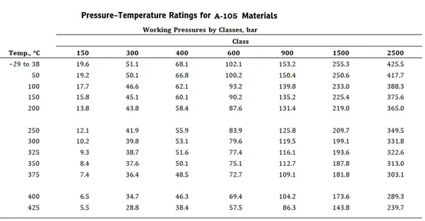
Pressure–temperature ratings are the maximum allowable working gauge pressures at the temperatures for the applicable material and class designation. So Pressure and Temperature Rating tables of ASME codes provide a limit of Maximum working pressure at which the flange can be subjected for a longer duration at a specified temperature. For intermediate temperatures, linear interpolation can be done. Refer to Fig. 1 showing a sample pressure-temperature rating table from B16.5.
Fig. 1: Pressure Temperature Rating Table for A-105 material.
From the above table, the following important points can be noted:
With an increase in temperature, the pressure-withstanding capability of the same material decreases.
With an increase in pressure class rating, pressure capability increases.
With a change in flange material pressure-temperature table and pressure withstanding capability changes at the same pressure class rating.
The temperature shown for a corresponding pressure-temperature rating class table is normally the temperature of the pressure-containing shell of the valve or flange.
Types of Flange Pressure-Temperature ratings
Normally two types of pressure-temperature ratings are used for piping/pipeline flanges. They are
Pressure-Temperature rating for API flanges and
Pressure-Temperature rating for ASME or ANSI Flanges.
For oil drilling and wellhead system applications, API flanges are used which are based on the API 6A standard. The pressure-temperature rating for API flanges ranges from 2000 psi to 20,000 psi.
For all other applications, ASME or ANSI flanges are used which are based on ASME B16.5 for sizes up to 24″ and ASME B16.47 for larger sizes.
What are Flange Rating and Flange Classes?
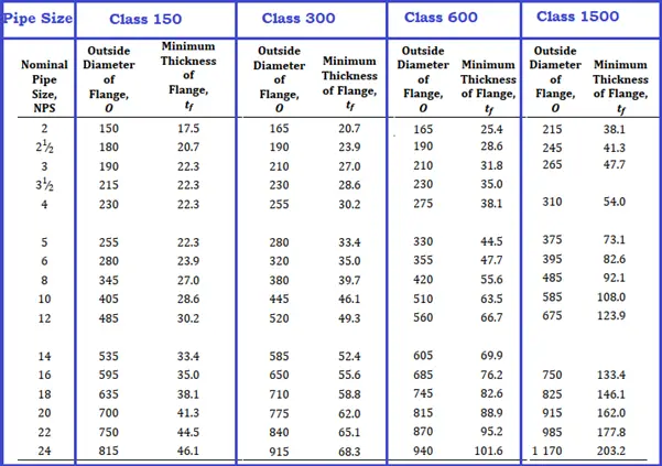
ASME/ANSI B16.5 standard provides seven flange pressure ratings: 150, 300, 400, 600, 900, 1500, and 2500. They are also known as Flange Class and denoted by Class, followed by anyone of the above-mentioned dimensionless numbers. They are also referred to as “Pound Rating” or Pressure Class Rating.
A few important features of flange classes are:
Fig. 2: OD and thickness Differences with respect to Pressure Rating Class
The higher the flange rating, the higher the pressure it can withstand at temperatures.
Flanges with higher ratings have more thickness (Refer to Fig. 2) and more weight and are stronger as compared to flanges with lower ratings.
With the change in pressure rating class, flange dimensions vary, and hence, the flange of one pressure class may not fit with its higher or lower class flange.
With the increase in pressure rating, the number of bolts increases which increases the bolt area. The increase in bolt area reduces flange leakage tendency by increasing force and moment-carrying capability.
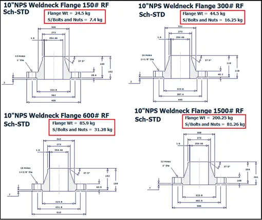
Refer to the following image (Fig. 3), produced from Pipe Data Pro to show you an idea of dimensional and weight differences for a 10-inch NPS Sch STD.
Fig. 3: Flange difference with respect to pressure class
Sample Calculation for determining Flange Rating
Let’s Assume We have to select an ASME B16.5 flange for a Carbon Steel pipe carrying fluid at 300 Deg C design temperature and 50 bar design pressure. To select the proper flange Refer to figure 1 which shows the pressure-temperature rating for CS (A-105) material.
From the Figure, We can see that the Maximum Pressure that the A-105 flange with 150 pressure class can withstand at 300 Deg C Temperature is 10.2 bar which is lower than our design pressure (50 bar). So not suitable.
Next, we will move to the next higher class i. e, pressure class 300. Here the maximum pressure capability is 39.8 bar which is also less than 50 bar. So rating class 300 is also not suitable.
Now e will move to the next higher class i. e, pressure class 400. Here the maximum pressure capability is 53.1 bar which is more than our design pressure.
So Selected flange class is 400.
Calculating Rated Flange Pressure
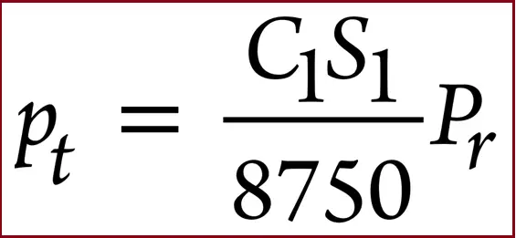
As mentioned in Appendix A of B 16.5, the pressure-temperature ratings for Class 300 and higher can be derived by the following equation:
ASME B 16.5 Rated Pressure Calculation Formula
Here,
C1 = 10 when S1 is expressed in MPa units and the resultant pt will be in bar units (C1 = 1 when S1 is expressed in psi units and the resultant pt will be in psi units)
Pr = pressure rating class index. For all designations, Class 300 and above, Pr is equal to the class designation (e.g., for Class 300, Pr = 300).
pt = rated working pressure, bar (psi), for the specified material at temperature T
S1 = selected stress, MPa (psi) for the specified material at temperature T.
Now if we apply the above equation for the above-mentioned sample problem, we will get the following output.
Here,
Pt=50 bar
S1=133 Mpa
C1=10
Hence Pr=(8750*50)/10*133= 329.
As the calculated Rated working pressure is more than 300, we will select class 400 for the flange.
PDMS or Plant Design Management System is a highly popular Engineering Design software developed by AVEVA. Its easily customizable user-friendly feature and multi-user supports in the multi-discipline environment make it the number 1 choice for many renowned engineering, design, and construction projects in the onshore and offshore industry. PDMS possesses separate modules for piping, equipment, structure, ducting, and cable trays. The software can be easily customized based on client specifications and catalogs and has a fully colored 3D environment.
What is PDS?
PDS or Plant Design Systems is an intelligent computer-based plant design engineering software package developed by Intergraph (Currently Hexagon). Starting from the year 1980, PDS is believed to be one of the pioneers of the 3D design industry. PDS can be used for projects ranging from small-scale revamp jobs to multibillion-dollar onshore and offshore platforms, refineries, chemical, and petrochemical plants.
PDMS vs PDS; Differences
From the above paragraphs, it is clear that both PDMS and PDS can be used for the design of any project. But most of the time designers ask, Which one is better between PDS and PDMS? According to user experience and technical flexible functionality, PDMS is far better than PDS. The following table will list down major differences between them.
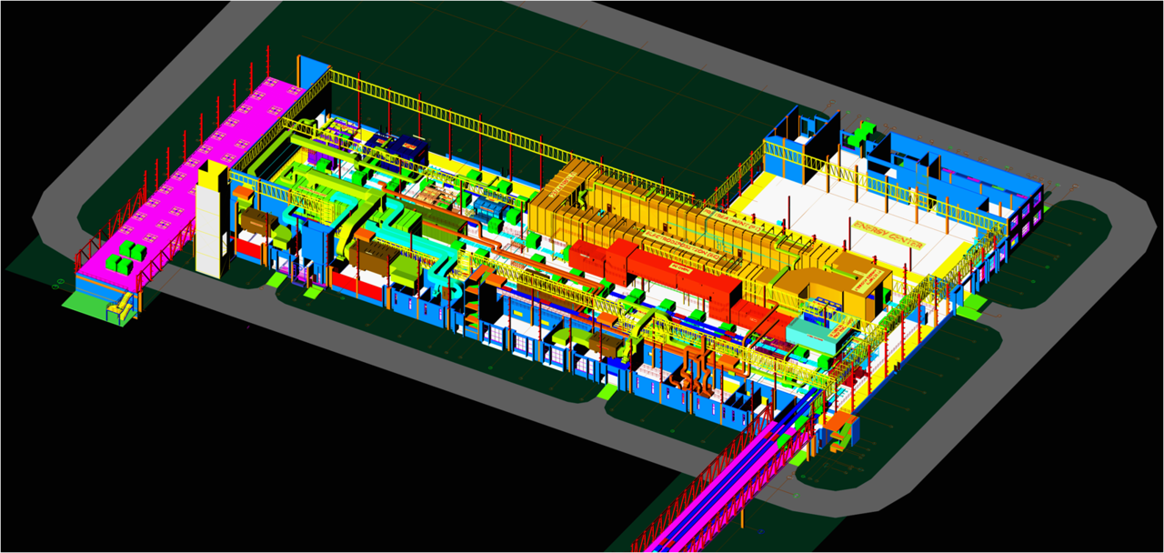
Typical 3D Graphic Model
Sr. No
Parameter
PDMS
PDS
1
Modeling & Design Environment
PDMS provides working in a shared or wire-line 3D environment. It has a higher level of visualization on the desktop for all engineering disciplines. Fully multidisciplinary 3D model.
Predominantly wire-line in day-to-day work. PDS can design in full-color shade but it is a static image. Image rotation or zooming is not possible. In PDS, HVAC, Raceway, etc. have separate applications.
2
Access Control
The access control of specific disciplines or objects in PDMS is easier.
Access control in PDS is much more difficult.
3
Data Handling
In PDMS, there is no limit on the job size. The software runs smoothly and at high speed.
PDS forces the designer to split big projects. Dependency of admin works is more with more complexity.
4
Database Architecture
PDMS database is open and easily accessible using the toolkits provided. The user simply navigates around a hierarchical project structure of the invisible PDMS database. The major advantage of the multi-disciplinary database of PDMS is that the interference checking between those disciplines will not have errors due to stepped data release.
PDS holds information in model files. The graphical information is stored in .dgn files. Associated with this are the .drv files with some attribute data and the link from the graphical files to the oracle database. Standard SQL links to Oracle are used to write and read information from the database. On multi-disciplined smaller projects, the user can not swap between different disciplines in the same reference file as the application ware (GUI) is different between different disciplines. The only option for the user is to come out and re-enter the system which wastes time.
5
Attribute Data
In PDMS the attribute data is stored in the same database as the graphical information and is protected from the user by the applications.
The oracle database is linked with the element via hidden stored user data. Items can be given the same name. Therefore there is no integrity of data. The .drv file which is an ASCII file can be edited in a standard editor outside of the system.
6
Revision Management
According to project procedures, PDMS is fully customizable to ensure available data is always fully controlled. Features like Change history, revision status, change highlighting on deliverables, rollback of database to any previous version, etc. are strong points of PDMS
PDS does not provide such features
7
Creating projects from previous old projects
User-friendly for extracting and re-using data from old projects.
Need PDS experts to extract and reuse old project data.
8
Mass Manipulation of Item
Easy
Very Difficult
9
Administration Effort
Less. PDMS allows work breakdown of projects for modification. PDMS has internal data access control as well as external.
High. PDS does not have such work breakdown features. There is no internal data management in PDS. Access permission to files is done at an operating system level.
10
2-D Integration
AutoCAD
Micro-station
11
Global Work Capability
Work and data can be easily shared globally across multiple locations
Limited
12
Compatibility with Latest Microsoft Technology
Compatible
Not-Compatible
13
Automatic Drawing Extraction
Can be configured
Not Possible
14
Creation of user-defined command
Possible
Not-Possible
15
Project Resource (No of Licence and Man hour ) Cost
20 to 40% less as compared to PDS
more
16
Online Clash Checking
Possible
No Online clash detection facility
17
Exact 3D Clash Location
Provide. PDMS maintains a spatial volume map of the design while users are working. All disciplines are available for checking at any time and automatic sketches of a clash can be output. PDMS can also recognize the difference between ‘touches’ and normal clashes.
Does not provide. PDS is not based on solid geometry. It defines envelope files and is a batch-only function because the clash check program draws circles around the clashes and must, therefore, open the Micro-station drawing (model file) with write access. Also, PDS cannot have negative volumes which result in many ghost clashes.
18
Insulation modeling
possible
No insulation specification with the thickness table is available. Provided only as a reference to the pipe.
19
Modification of job
Easy. PDMS is very flexible and allows to drag and modify piping sections. Some useful options for positioning piping items to the ‘Top Of Steel’ or ‘Bottom Of Pipe’ are available in PDMS.
Difficult. In PDS you can not declare a clearance from another item when positioning a component other than snapping on the graphic representation of an element.
20
Online data consistency checking
Complete consistency check with the report is possible
Not possible
21
Export to Design Review Tools
Superior
Inferior
22
File Size
Database size is less than PDS. Database by PDMS are up to 70% smaller than the PDS database for the same project
Size is more as for each item information is stored individually.
As the more complete model of the parts, BOM extracted is more accurate
Less Accurate
24
Corruption Problem
PDMS being a single integrated database, there is no link to corruption problems
Many PDS customers regularly experience database linkage corruption because of its standard multi-write relational Oracle database. Once information is written, it is impossible to undo or quit the work session.
About the Author: Part of the article is authored by Mr. Amir Razmi, an International dynamic and multi-functional chemical engineer with more than 14 years of experience in engineering and EPC of oil and energy projects from pre-contract activities to execution, and closeout.