In this AVEVA E3D Tutorial, we will explain the steps for creating a vertical column (Tag: C-1101). The E3D Equipment modeling steps are shown using two different methods. Let’s dive into the article.
E3D Equipment modeling Steps
Go to the Discipline tab of the software to select different sectors like Piping, Structures, and Civil as per requirements. For our case, Select Equipment Tab as shown in Fig. 1A.
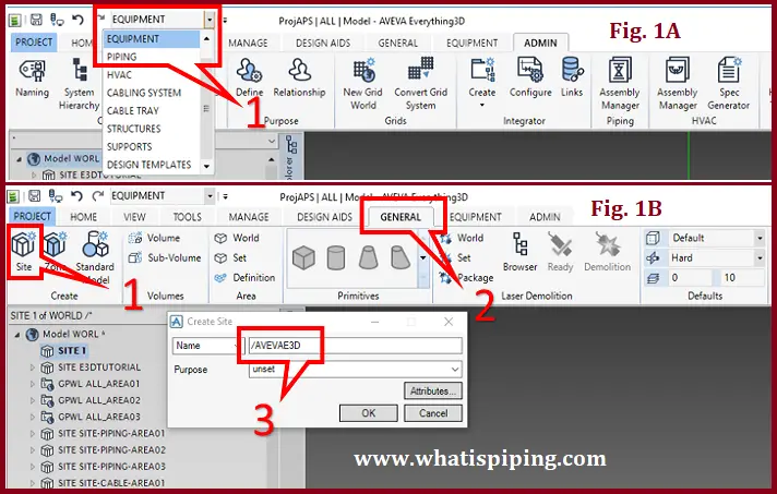
In E3D, we should first create a Site, Zone, etc. similar to AVEVA-PDMS. For the “Site” creation go to Create click on Site In the General tab (Refer to Fig. 1B) and provide a name as you want. Here, I am giving the name Aveva E3D. Don’t provide space between words. Click on Ok.
For Zone creation click on the Zone Tab under Create, give a suitable name for the Equipment (Refer to Fig. 2A) and click OK. Next, Go to the Equipment Tab, and in create tab click on Equipment. Give name as C-1101 as per equipment datasheet and hit Enter. In the Position tab, Keep East, North, and Up as 0 mm for the time being. We will fill in these values later. Refer to Fig. 2B. Now, Under attributes, Give a Description name as Cracking Tower. You can fill in the remaining details if you have them, otherwise, you can keep it blank and press OK to continue further.
Method 1: Creating Equipment by Primitives
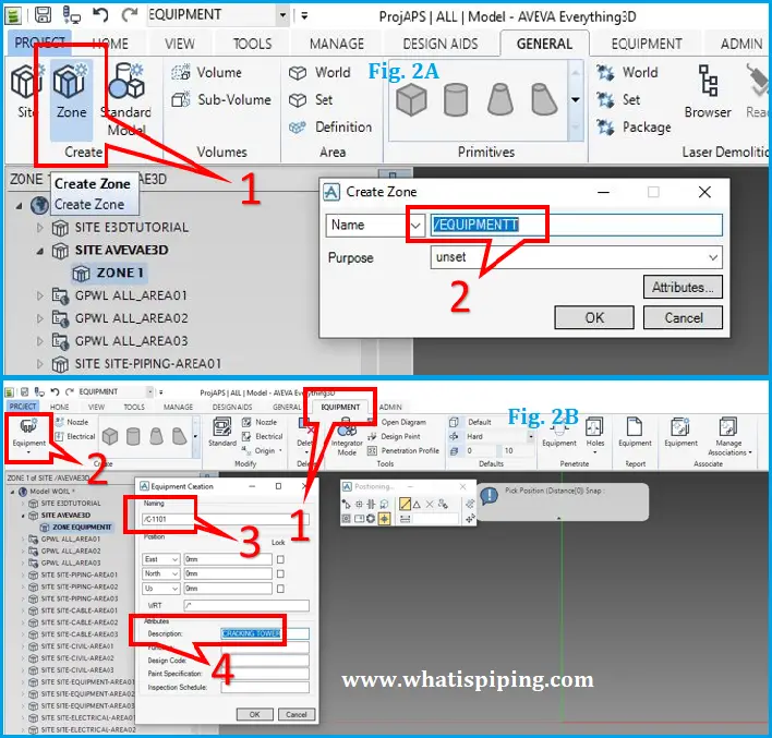
In Method 1, we will be creating the equipment by Primitives (Not Standard Equipment). So, Select Cylinder shape from the Create tab. Refer to Fig. 3A.
Here you can see the drawing, same as AutoCAD the cursor will be displayed (Fig. 3B). Now give the value for East : 0 mm and hit the Tab button on the keyboard it will lock the position, you can see the red lock symbol in each Easting, Northing, Up, tab after Hit Enter.
Now it’s time to specify the diameter and height of the column. Enter 1413 mm as diameter and 14076 mm as height as shown in Fig. 3C.
You can now see the vertical cylinder on the window.
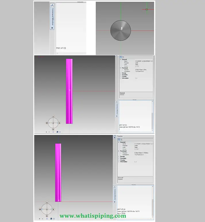
Method 2: Creating the Equipment by using Commands
Go to the Tools tab and click on Command for the command window.
Give the command PIN1 at CE and Enter.
You can see PIN1 at the center of the window.
Now write New cylinder height 14076, and diameter 1413, and Press Enter.
This is the shortcut command for creating a cylinder in E3D keeping the view in Elevation.
The origin of the cylinder is in the center. But as per the drawing, the cylinder base should be at the bottom, not the center. So, Give command as
By u 7038 (half the height of the cylinder) and hit Enter.
U means up. Now the cylinder is placed above as you can see in Fig. 4.
Now before proceeding to the next section, Let’s learn a few settings.
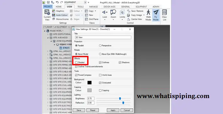
For wireframe view press the F11 key on the keyboard.
Or else go to the View tab and click on the Current view in the settings tab.
The view settings window will open.
Under the effects section, uncheck shaded then apply and cancel. Refer to Fig. 5.
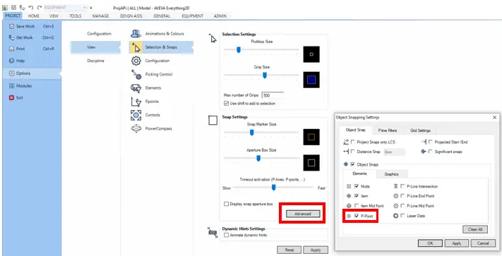
Next, go to Project tab -> click Options -> View -> Selection & Snaps
Click Advanced under Snap Settings and Under the Object tab uncheck P-point and press OK. Refer to Fig. 6
Modeling the Cone Ends of the Column
Now for the Cone
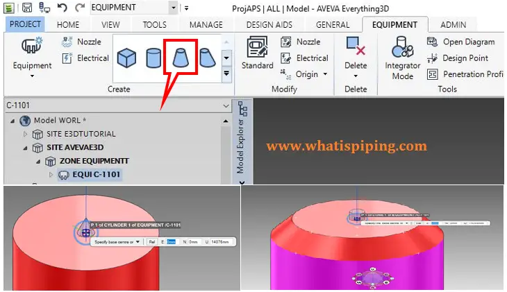
Click on Cone from the create tab.
After clicking on Cone (Refer to Fig. 7A) move the cursor to the top of the Center of the cylinder, you can see the top P-point Of the cylinder with a square shape.
Click here on top of the cylinder.
Now give the diameter as 1413 mm and press enter.
By moving the cursor upside of the cylinder, Give height as 280 mm and hit enter.
Now give the next diameter as 1067 mm and click enter
Now the cone is ready.
For the next steps of the cylinder, Select the Cylinder shape from Create tab.
Go to the cone, again click on the top P-point of the cone
Now give Diameter as 1067 hit Enter and Height as 7849 Hit Enter as per the datasheet.
Refer to Fig. 7B and 7C
Modeling the Dish End in E3D
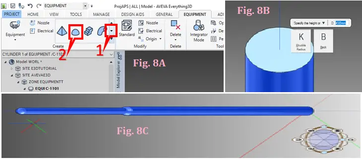
For the Dish-end (Refer to Fig. 8), Go to the Equipment tab and click the Down arrow in the create tab. Then click on the Dish shape. After clicking on Dish, move the cursor to the Center of the cylinder’s top P-point. Click here on top of the cylinder
Now give diameter as 1067mm enter. After that, E3D will ask for the height of the dish. Now press the down arrow on the keyboard you will be able to see in the window two boxes which are knuckle radius & back.
Click on the knuckle radius and give the value as 20 mm and press Enter.
After the knuckle radius, provide the height of the dish as 200mm and Hit Enter.
Now the cylinder is ready as you can see in Fig. 8.
Modeling the base plate of the column in E3D
For modeling, the base plate click on the box shape as shown in Fig. 9
Give the value as follow:
East: -1050 mm press the tab button, North: -1050 mm again tab button Up: 0 mm and hit enter.
East: 2100 mm press the tab button, North: 2100mm again tab button Up: 0mm and hit enter.
Now specify the Z-length (width of base plate)
D: 25mm enter as per the datasheet.
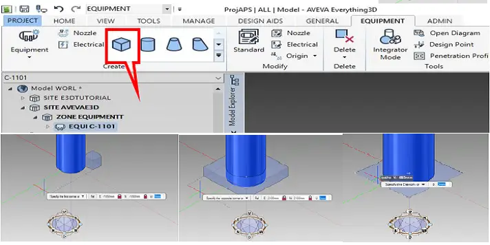
Column C-1101 is ready.
Video Tutorial for E3D Column Modeling
I am sure still, you have many doubts about the above steps. Hence, the video tutorial for the above-mentioned column is attached herewith for a clear understanding. Please like and subscribe to the channel (Bounce Back) for more updates. You can download the column datasheet from the links provided in the you-tube video description.
AVEVA E3D Online full training courses
If you are looking for an online complete step-by-step E3D training course then the following course will help to fulfill your hunger. Kindly click on the below-mentioned subject, review the details of the course and then enroll to proceed:
AVEVA E3D Training Course From Beginner to Advanced 2021
Few more useful articles for you.
Tutorial on Pipe Modeling using AVEVA E3D software
Why is Aveva PDMS better than Intergraph PDS?
PDMS Video Tutorial/Lessons for Beginners
START-PROF Piping Stress Video Training Series