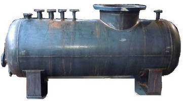
Equipment nozzles are the openings through which fluid enters or exit the equipment. To create the path for fluid a part of the equipment must be cut, which weakens the equipment. So nozzle connections are weaker sections of any equipment. So design must be checked to safeguard the weak nozzle section. This is normally done by adding extra metal in form of reinforcement known as nozzle reinforcement.
The need for the provision of a reinforcing pad around the such opening is ascertained and the pad thickness is arrived at using the area compensation method stipulated by the codes. In this article, we will explore the Nozzle reinforcement pad calculation methodology for a cylindrical Nozzle provided on any shape of a vessel or a closure.
Area Compensation Method for Nozzle Reinforcement
The philosophy of the area compensation method is very simple. The load-bearing metal cross-sectional area that is lost due to the opening is identified. It attempts to compensate for this area loss by providing extra thickness (i.e, nozzle reinforcement) in the affected vicinity of the hole.
It is important to get a correct picture of the area that is purported to be lost due to an opening. Consider the flat plate shown in Fig. 1. Let it be stretched in one direction such that the stresses are just equal to the allowable stress. Let the plate thickness be “t” everywhere. We now contemplate removing a circular area of diameter “d” in a lane of width “d” as shown in Fig. 1A.
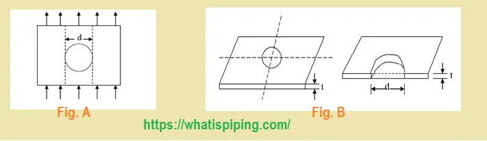
The load-bearing metal cross-section lost due to the removal of the disc of diameter “d” is clearly not the area of the circle. Instead, it is a rectangle of width “d” and thickness “t” as shown in Fig. 1B above.
This lost area can be compensated back to the plate by welding a disc of thickness “t” of outer diameter “2d” and inner diameter “d”. This would provide an extra area of “d*t /2” on either side of the lost area “d*t” as shown in Fig. 2 below.

This is the essence of the concept of area compensation. We place, if necessary, a plate around the circular opening of the diameter of the opening, and suitable thickness. It offers an extra load-bearing cross-section in the affected vicinity which reduces stress intensification.
The actual calculations are more elaborate. The calculation incorporates the decision steps that lead to the wall thickness calculations. The regulation thickness is then corrected for corrosion/erosion allowance and mill tolerance on plate thickness. And finally, the next available commercial thickness is recommended to select.
Nozzle Reinforcement Calculation Methodology
Let us consider a cylindrical vessel/pipe of outer diameter Do subject to an internal design pressure of P. Let the corrosion allowance be € and mill tolerance ± M %. Let the recommended plate thickness be T.
Let a nozzle (or branch connection) of outer diameter (OD) do, Inner Diameter (ID) di, and nominal thickness t =(OD-ID)/2 ) be required to be provided on this vessel/pipe (header). Let the mill tolerance be m%. Corrosion allowance and design pressure would be € and P for the header as the vessel and nozzle face identical service conditions.
Self-Compensating Nozzle
It helps to consider the steps that go into recommending the header and branch thickness. The minimum thickness for pressure is calculated, corrosion/erosion/mill tolerance allowances are added and the next higher commercial thickness is recommended. Most of the time, there is an extra thickness available in the header design to handle stress intensification of the affected zone. The compensation area can take advantage of this discount. Often, this extra area available is more than the area lost and in such cases, No extra area by way of reinforcing pad is required. Such a nozzle is called a “self-compensating nozzle”.
In a similar way, The nozzle thickness is calculated. So some extra thickness (and hence area) is available in the nozzle itself. This available extra nozzle thickness up to a height of H1 above the header OD can be accounted for in the area available in the original design. This thickness can be discounted in the calculations of the actual area that is lost and which must be compensated through the provision of a reinforcement pad.
Stub Nozzle and Protruding Nozzle
The basic nozzle types are two. We can have a nozzle that is protruding. In this case, the nozzle pipe actually extends into the vessel or header to a certain extent. This could be a process requirement. For example, if such a nozzle is used for the inlet to a vessel, the liquid coming in would nicely fall into the vessel Rather than trickle along its wall. If that is what the process requires, we could provide such a nozzle.
Another type is a flush or stub nozzle. It does not protrude. Fig. 3 explains the Flush (Stub) Nozzle and Protruding Nozzle definitions.
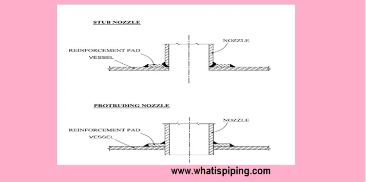
If the nozzle is protruding inside the header, its portion up to a depth of H2 is also considered as providing an extra area to handle stress intensification.
Basically, the feeling here is that once the nozzle is in place, the header/nozzle is a single assembly and any extra provision of the load-bearing cross-section in the assembly in the affected zone can be counted upon to offer help in stress management.
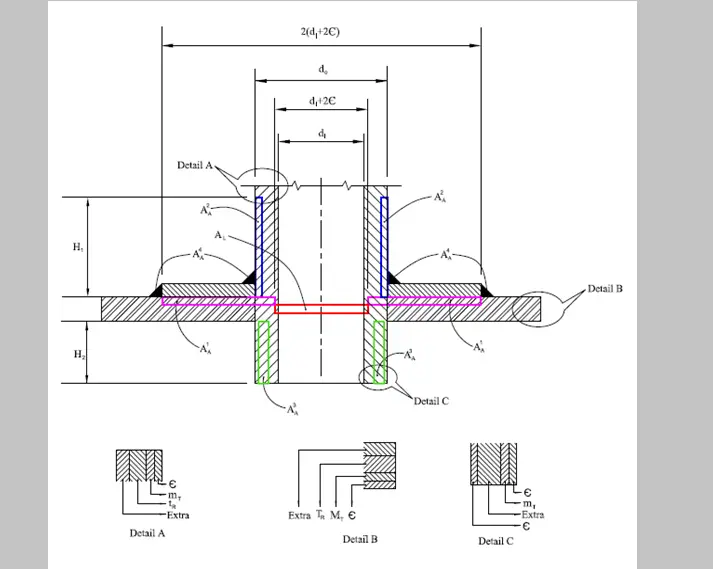
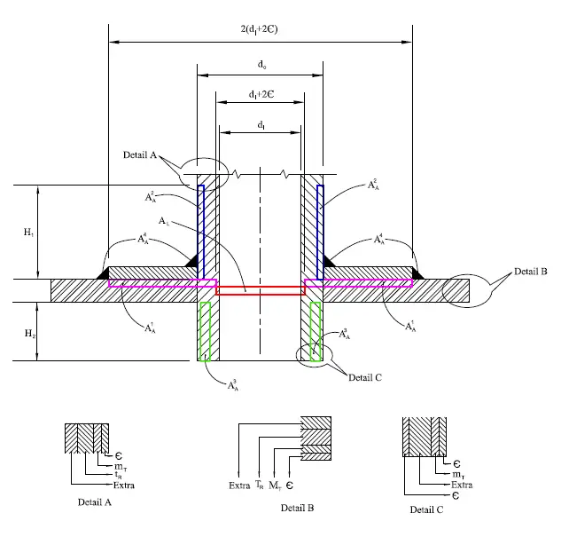
The affected zone is simply up to a width of double the opening diameter on the header, a height of H1 along the nozzle portion outside the header, and a depth of H2 on the nozzle portion protruding into the vessel as shown in Fig. 4.
A reinforcing pad on the nozzle is provided when the area “lost” due to cutting the opening is more than the area “available” in the header portion and the nozzle portion (above the header and inside the header). This area of accounting has several nuances further to try and avoid the provision of a reinforcing pad.
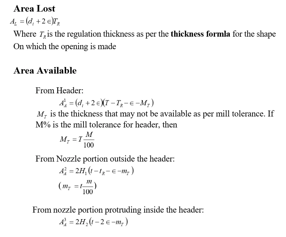
The area that is lost is considered as a rectangle of width equal to the “diameter” of the hole and height equal to the “thickness”. Each term requires one to be qualified further.
We would like our design to be functional right through service life. Corrosion would have caused an increase of the nozzle ID (which is the size of the opening also) to di + 2€ over this period. This, therefore, is considered the design basis for the diameter of the opening to be used in reinforcement calculations. As a consequence, the affected area on the header extends to a circle of diameter 2(di + 2€). The Reinforcing pad if provided will have this as its OD.
The “thickness” to be used in calculating the area lost is also important. What is indeed lost is the regulation thickness. The rest which comprised of the allowances, tolerances, and extra is not a consequence here. The regulation thickness would have helped keep the stresses at the allowable level. This thickness is what is “missed” as an opening is made.
A couple of other points are also very important. The opening of the nozzle is normally not located on an existing weld joint of the header or its vicinity. A weld as well as an opening is a weakness in the structure and fabrication rules dictate that both should not occur simultaneously. If this is so, then the regulation thickness for the header should be calculated using the Weld Joint Efficiency value as 1 in the appropriate regulation thickness formula for the header shape. The regulation thickness thus may not be imported directly from previous calculations done at the time of header design. Note that, this considerably reduces the value of regulation thickness, thereby lowering the estimate of the area lost.
Another point is regarding choosing the formula for the regulation thickness itself. It is the code formula for a shape “seen” by the nozzle. It may not make a difference if the nozzle is placed on a sphere, hemisphere, cylinder, flat plate, or ellipsoidal closure. For a dished (tori-spherical) closure or a cone housing a nozzle, it does make a difference.
If the nozzle is on the “crown” of a dished closure, the shape around it is actually a sphere with a diameter double that of the vessel. While designing the closure, the formula pertaining to the dished closure would have been used. While calculating regulation thickness to be used in calculating area lost, one should use the formula for a sphere instead. Note that this consideration also reduces the value of regulation thickness, thereby lowering the estimate of the area lost.
In a similar way, the nozzle thickness of a cone is arrived at using the base diameter of the cone. While moving towards the tip of the cone, the code thickness requirement decreases, and extra thickness increases. So to take benefit of this extra thickness in reinforcement calculation, one should calculate the regulation thickness using cone diameter at a level near to the center of the opening. Note that this consideration also reduces the value of regulation thickness, thereby lowering the estimate of the area lost. In fact, a properly located nozzle on a cone can often be made “self-compensating”.
Calculation of Load-Bearing Area
Let us now calculate the load-bearing metal area affected due to the presence of an opening. Refer to Fig. 5.
The last expression needs some clarification. The protruding portion of the nozzle is subject to the same pressure on either side of its wall. The differential pressure is thus zero on this wall and no requirement for regulation thickness. But, corrosion is eating into this wall from both inside and outside. Corrosion is thus twice the corrosion allowance for the expected service life.
The participating heights of the nozzle, H1, and H2,(participating in sharing the extra stresses ) are given as follows:
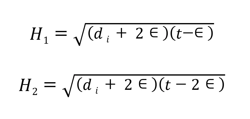
Note that for a non-protruding nozzle, H2 =0. The regulation thickness of the nozzle, tR, is imported directly from its previous calculations done for deciding nozzle thickness. As the entire nozzle with its seam welding is in the affected area, no correction for weld joint efficiency is required for this calculation.
The balance sheet attempts to hammer down the estimate of the area lost.
The available is calculated by looking at the area available in the vicinity. In fact, even the “weldment” area in the affected rectangle is accounted for in the area available if such estimates are available.
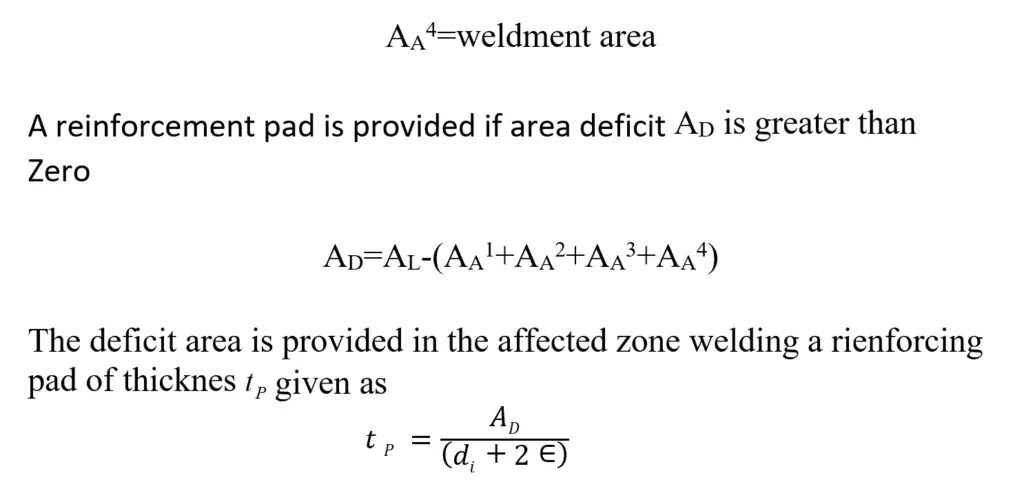
The formula is self-explanatory in view of the discussions above and the figure (Fig. 6) below.
Although not explicitly stated, it is presumed that the reinforcing pad is of the same material as that of the header/nozzle as welding together dissimilar metal could lead to galvanic corrosion. However, as the pad is not exposed to the corrosive process fluid, if a dissimilar material is chosen for the pad for economic considerations, an appropriate correction to the pad thickness should be called for.
Codes recommend an upward revision of the thickness if the pad material’s allowable stress ( Sa pad ) is lower than that of the header/nozzle (S). Logically, the revision is as follows.
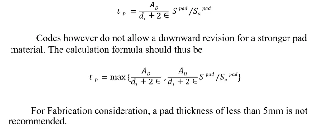
Note that Fabrication consideration does not recommend a pad thickness of less than 5 mm.
Few more useful resources for you.
A short briefing about REINFORCING PAD
Dish and Nozzle Centerline Distance Calculation from Nozzle Orientation of Pressure Vessel
A short Presentation on Basics of Pressure Vessels
Brief Explanation of Major Pressure Vessel Parts
10 points to keep in mind while using project-specific pressure vessel nozzle load tables during stress analysis.