Turbine piping stress analysis is one of the most critical analyses in piping design. It is due to the following reasons
- Turbines are strain sensitive and have less allowable nozzle loads.
- Friction in the supports near turbine nozzles increases the loads to a high extent.
- The turbine-connected system has a high fluid temperature.
- A combined nozzle study following NEMA SM23 is required and it is difficult to qualify combined nozzle loads.
- Various Spring supports are used to qualify the nozzles.
In this article, we will explain the Stress Analysis steps after a brief discussion about turbine piping layout considerations. Piping Stress Analysis Software Caesar II is used for the analysis of Turbine Piping.
Turbine Definition
A Turbine is rotating equipment where the kinetic energy of the moving fluid is converted into mechanical energy by rotating a bladed rotor. Turbines are used as mechanical drivers for other machines (for example, compressors) in the refinery, chemical, or petrochemical industry. Turbines may be of various types as mentioned below:
- Steam Turbine
- Gas Turbine
- Transonic Turbine
- Contra Rotating Turbine
- Stator less Turbine
- Ceramic Turbine
- Shrouded Turbine
- Shroud less Turbine
- Bladeless Turbine
- Water Turbine
- Wind Turbine
Working Philosophy of Turbine
Steam and Gas Turbines basically work on either Impulse or Reaction philosophy.
Impulse turbines change the direction of the flow of a high-velocity fluid or a gas jet. The resulting impulse spins the turbine and leaves the fluid flow with diminished kinetic energy. There is no pressure change of the fluid or the gas in the turbine rotor blades, all the pressure drop takes place in the stationary blades (the nozzles)
Reaction Turbines develop torque by reacting to the gas or fluid’s pressure or mass. The pressure of the gas or fluid changes as it passes through the turbine rotor blades. A casement is needed to contain the working fluid as it acts on the turbine stage(s), or the turbine must be fully immersed in the fluid flow.
Layout Considerations for Turbine Piping
- Enough flexibility in steam turbine piping has to be provided to make up for thermal stresses as these lines are subjected to high temperatures by providing long-run pipes, expansion loops, and bends.
- Line routing should be fabricated by bending or welding processes instead of flange connections to avoid flange leakage in steam lines.
- All main area piping has to be done by a vendor.
- Steam traps are to be provided in all steam lines to avoid condensate accumulation.
- All gas turbine piping vents are to be provided in a high, open, and safe area.
- Expansion bellows can be used in large-diameter and short-span, rigid piping systems. (Generally mounted between turbine outlet nozzles and condenser)
- All supporting is to be done while keeping the friction at a minimum, for this hanger supports (not recommended for very high vertical displacements) and Teflon pads can be used.
- It’s preferable to follow ½ or 1⁄3 times of normal support span for turbine piping.
- Variable spring supports with lower variability should be used. As load variability is not taken care of by Caesar so it is the analyst’s responsibility to keep it as low as possible to avoid the transfer of reaction forces and moments due to variable loads to the nozzle connection.
- Spring with a larger variable load is allowed if its spring stiffness is low as in the case of constant springs. Bottom-mounted F-type springs should not be used generally to avoid friction if used Teflon pad should be provided.
Caesar II Simulation and Stress Analysis Procedure for Turbine Piping
There are two types of procedures that can be followed for Turbine modeling.
When Nozzle movements/displacements are provided by the vendor:
In most cases, the turbine nozzle movements are provided by the vendor in the datasheet or GA drawing. With that, Caesar’s modeling becomes very easy. The nozzle displacements provided by the vendor are entered at the nozzle connection points (flange points) to the equipment with a C-Node, the rest of the piping has to be modeled as per the normal procedure. However, remember to consider the proper direction of those displacements while entering Caesar II Input Spreadsheet.
When Nozzle movements/displacements are not provided by the vendor:
When nozzle displacements are not provided, the modeling has to be done as per the GA drawing of the equipment provided by the vendor. All detailed drawings and support details with dimensions should be seen clearly to avoid any modeling errors.
The main anchor block of the equipment assembly is the point from where the machine is supported rigidly.
The modeling procedure is explained in this section with an illustrative example for proper understanding.
The Caesar dump (Fig. 1) attached below shows how the modeling is done for the turbine with the inlet and exhaust nozzle attached. Here we will correlate the Caesar dump with the Equipment GA drawing to simulate the configuration.
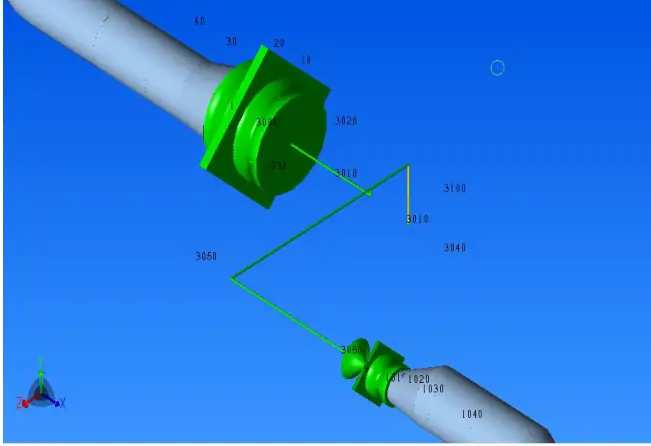
Steps for modeling the Turbine
- Model elements 10 to 20 as piping flange as per isometric (south direction) with piping design and operating parameters.
- Place an anchor on node 10 with C node as 1.
- Model nozzle flange from 1 to 3000 taking Temperature and pressure parameters of the turbine.
- From 3000 to 3010, model rigid element (length=305 mm from Fig 2, 3 & 4) taking Temperature and pressure parameters of the turbine.
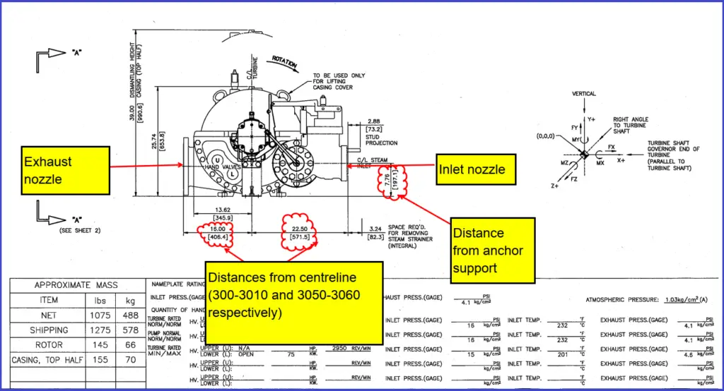
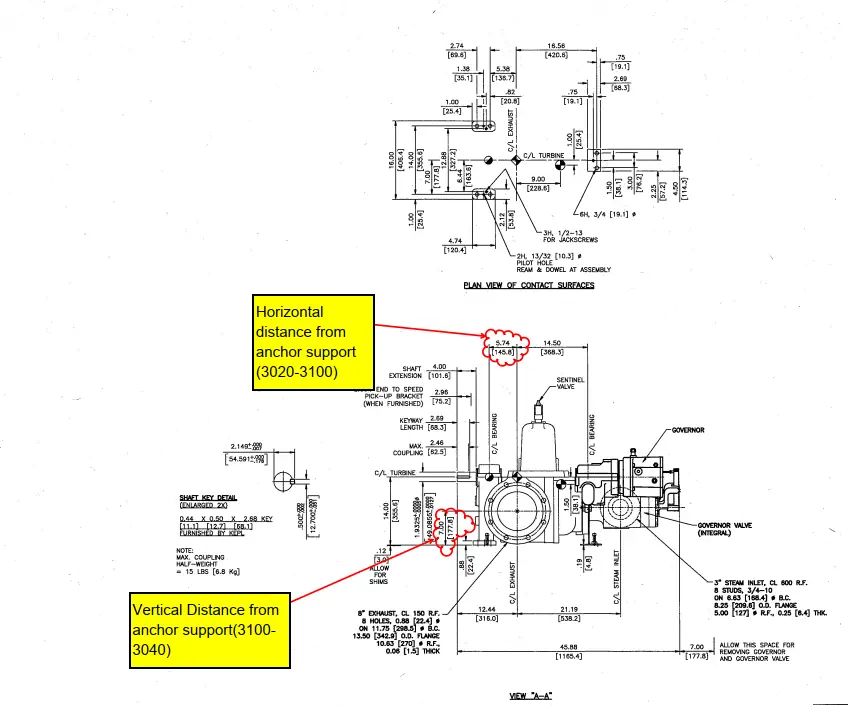
- From the 3010 to 3020 model the elevation difference of the exhaust nozzle with the inlet nozzle as 20 mm in a vertically upwards direction (see Fig 2 and 3).
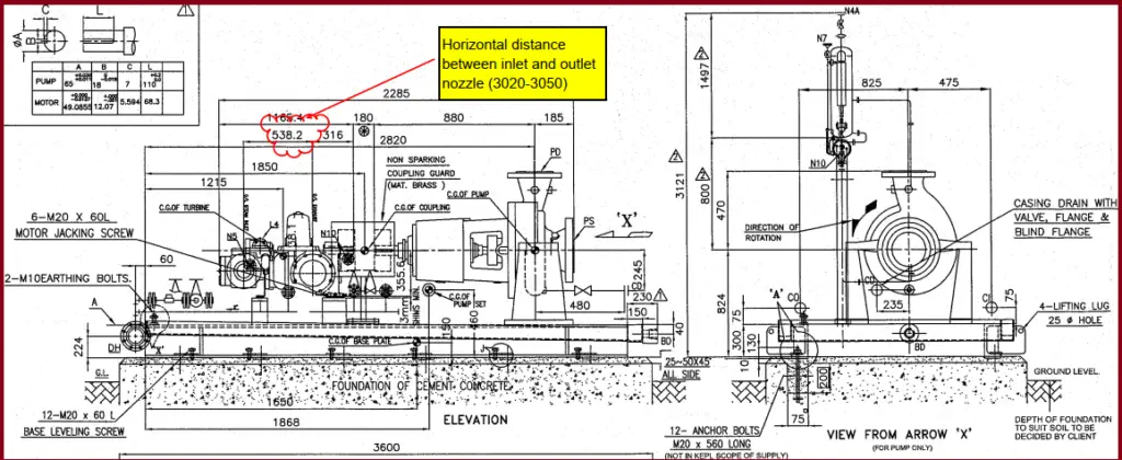
- Model element from 3020 to 3050 towards the west (see Fig 4 for dimensions (538.2 mm)).
- Model 3050 to 3060 up to the inlet nozzle towards the south (For dimensions (478 mm) see Fig 2).
- From the 3020 model a rigid element, length= 148.5 mm in the east direction to 3100 (Fig 3).
- From the 3100 to 3040 model a vertically downward element length =177.8 mm (See Fig 3). At 3040 place an anchor point. (This point is the location from where the turbine assembly is rigidly supported).
All the Turbines can be modeled in this manner by following the GA drawing. There are certain difficult drawing arrangements that require many data to get a clear idea of how equipment is placed. For this
purpose, all detailed drawings should be kept ready to avoid any modeling
errors.
Analysis & Output Phase
While modeling the nozzle with displacement (when the vendor provides displacement), the movements D1 (Displacement in operating condition) and D2 (Displacement in sustained condition) have to be added to the operating (W+P1+T1+D1) and sustained load case (W+P1+D2) respectively.
The rest of the load cases corresponding to occasional loads such as wind and seismic has to be prepared as usual.
The main and most important part of the analysis phase is nozzle load checking. NEMA SM23 (For turbines) provides guidelines and equations which help in cross-verifying the external moments and loadings on a nozzle. Nozzles for turbines are to be checked for individual loading as well as
combined loading.
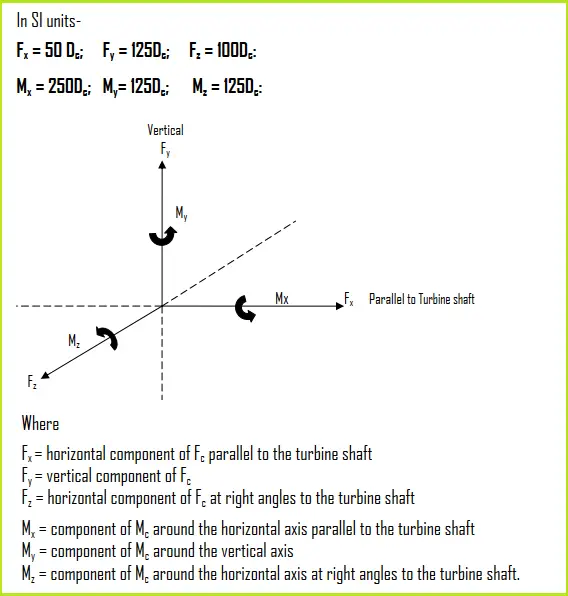
In the thermal analysis and nozzle load evaluation, the X-axis of the piping (As per Caesar) should coincide with the Compressor (Turbine) shaft axis direction.
Besides Caesar II also provides modules for NEMA SM23 in the database by which nozzle loads can be directly checked with the help of software in an easy manner.
Nozzle Load Checking per NEMA SM-23
For all rotating equipment following three types of nozzle load checking are performed
A. Individual Turbine Nozzle Checking
The total resultant force and total resultant moment imposed on the turbine at any nozzle connection should not exceed the values given below −
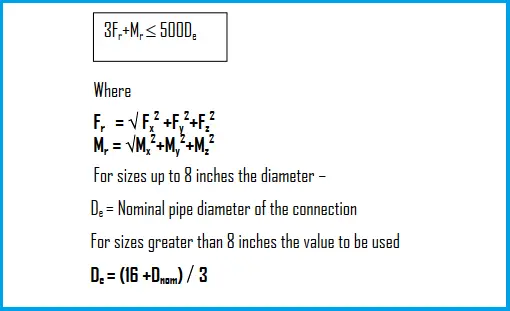
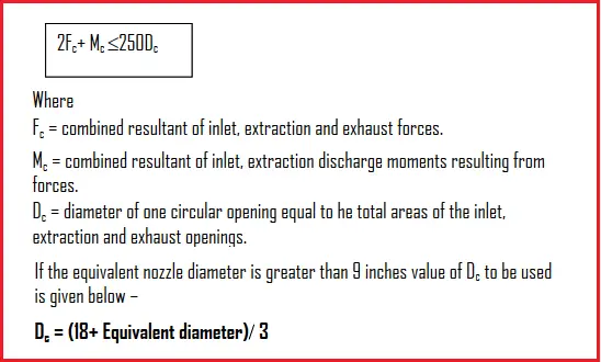
B. Combined Turbine Nozzle load Checking
The combined resultants of loads and moments of the inlet, extraction, and exhaust connection resolved at the centerline of the largest connection (mainly exhaust nozzle) should not exceed the following −
C. Individual Component Load Checking
The individual component forces of each nozzle should not exceed the following
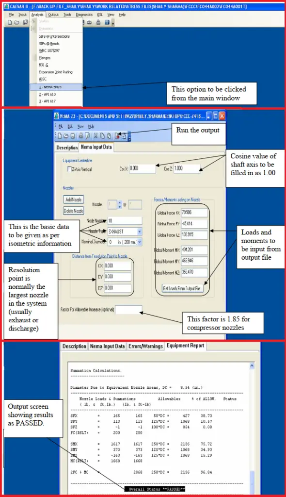
Caesar II NEMA SM 23 Module
Caesar II provides an inbuilt NEMA SM-23 module to digitally check turbine nozzle loads and extract the report. The steps for using the module are shown in Fig. 8.
Few Important points for Steam Turbine Piping Stress Analysis
- Ensure the correct Weight of the Valve, flange, and any in-line items, and mark the weight in the stress sketch.
- Branch piping (like drip legs etc.) greater than 2 inches should be included in the analysis.
- Check Insulation density carefully.
- Wherever spring supports are used, define spring rate and cold load.
- Alignment or WNC check with springs in the locked and unlocked condition is mandatory for turbine (compressor) piping systems.
- Few companies require to perform the hot-cold check for turbines. In that case, From the steam header to the first block valve, consider the same as the line temperature and From the block Valve to the turbine nozzle, consider ambient temperature (not working) and check the nozzle loads as per the code allowable.
Few more useful Resources for you.
Stress Analysis of Centrifugal Compressor Connected Piping Systems using Caesar II
Stress Analysis of PSV connected Piping Systems Using Caesar II
Load Cases for Stress Analysis of a Critical Piping System Using Caesar II
Stress Analysis of GRP / GRE / FRP piping system using Caesar II
Stress Analysis of Vertical Reboiler Piping using Caesar II
Stress Analysis of Pump Piping (Centrifugal) System using Caesar II
Basics for Stress Analysis of Underground Piping using Caesar II
Stress Analysis of Jacketed Piping System using Caesar II
Stress Analysis of Column piping system using Caesar II
Stress Analysis of HDPE, PE-RT, PP-H, PP-R, PVC-C, PVDF Piping