
Pipeline Stress Analysis is quite different from normal plant piping stress analysis. Normally Pipelines run kilometers in length for transferring oil, gas, water, or sewer. There are two types of pipelines. Liquid Pipelines and Gas pipelines. Pipeline Stress Analysis of liquids is governed by ASME B31.4 whereas the same design standard for gas pipelines is dictated by ASME B31.8.
All my previous articles on this website describe the stress analysis methodology of piping systems using Caesar II based on ASME B31.3. But I received requests from many pipeline engineers to describe the pipeline stress analysis methodology. So in this article, we will explore the required steps for stress analysis of a pipeline system.
Pipeline Stress Analysis Considerations
The most fundamental difference between pipeline and plant piping is the very long length of the pipeline. A pipeline with kilometers in length produces a very large amount of expansion even though the design temperature of pipelines is normally less as compared to plant piping. A reasonable estimate of the movement and its interaction with the end resistance force afforded by connecting piping and equipment are very important aspects of designing a pipeline.
Pipeline thicknesses are generally less than plant piping thicknesses. It’s quite obvious to reduce pipeline material costs. Also, normally API 5L material is used.
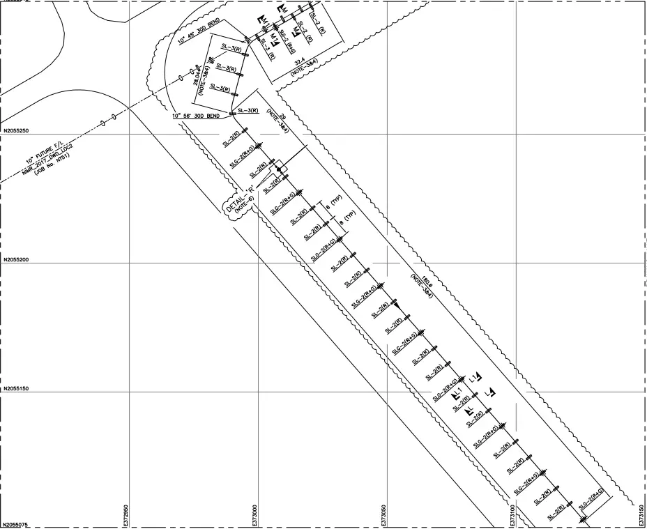
Pipeline General Arrangement Drawings are used for showing pipeline routes. These pipelines in most cases do not run parallel to any given direction. Refer to Fig. 1 for a typical sample of pipeline GA/Route plan drawing.
A large amount of pipeline movements are caused due to pressure elongation, also known as the bourdon effect. For plant piping bourdon effect is normally ignored but for pipelines, the pressure elongation is significant and is considered. So,
The total elongation for pipelines=Temperature Elongation+Pressure Elongation.
Pipeline stress Analysis is not as stringent as plant piping as the allowable values are much more as compared to plant piping allowable values.
Hydro-test pressure for pipeline stress analysis is normally considered as 1.25 times the design pressure which is less than the plant piping design pressure consideration.
The pipeline may be above-ground with road and wadi crossings or completely buried.
Pipeline Stress Analysis Software
Pipeline stress analysis software is the same as plant piping stress analysis software as all those software have the provision for changing the design code and running the analysis. So all the below-mentioned software are used as popular pipeline stress analysis software
- Caesar II by Hexagon
- Auto-Pipe by Bentley
- Start-Prof by PASS
- Caepipe
- Rohr II
Pipeline Stress Analysis Calculations
Pipeline Stress Analysis is performed for Sustained, Operating, Occasional, and Expansion Load Cases. The load cases are similar to plant piping analysis load cases. The main features for pipeline modeling are listed below:
- Pipelines possess a very long radius (25 D to 60 D) elbows. So bend radius must be provided.
- The buried depth of cover must be accurately entered into the soil parameters. Different pipeline segments normally have different buried depths as pipelines normally run on uneven surfaces.
- If pipe sleeves are used in buried parts those have to be modeled as above-ground parts with spacer supports at even distances.
- Normally expansion loops are provided at a distance of 500 m from the other expansion loop for above-ground pipelines.
- Pipelines turn at various angles (not 45 degrees or 90 degrees similar to plant piping) so those need to be modeled correctly from pipeline GA drawing.
- Pipeline models are created from Pipeline General Arrangement drawings or Route Plan Drawings (Refer to Fig 1 for a sample). Isometrics are not available similar to plant piping.
- In most cases, the aboveground and buried pipeline design temperature is different and needs to enter correctly.
- For buried parts of pipelines, proper soil data must be entered from soil reports by the civil team.
- There are no Sh values similar to B31.3. A pipeline normally runs for several kilometers without any fittings attached. Because of such simplicity, the stress in the majority portion of a pipeline is quite predictable. Taking advantage of this characteristic, the code’s allowable stress for a pipeline is greatly increased, as compared to that for plant piping. All allowable values are linked with Sy (Specified Minimum Yield Strength) as the allowable stress of a pipeline is mainly to protect the pipe from gross deformation. Whenever you select B31.4 or B31.8 in Caesar II all Sh value fields become grey.
- There is nothing like liberal stress in pipeline stress analysis.
- Pipelines are always connected with piping systems. So in the same stress system, both piping and pipeline codes may be required to use.
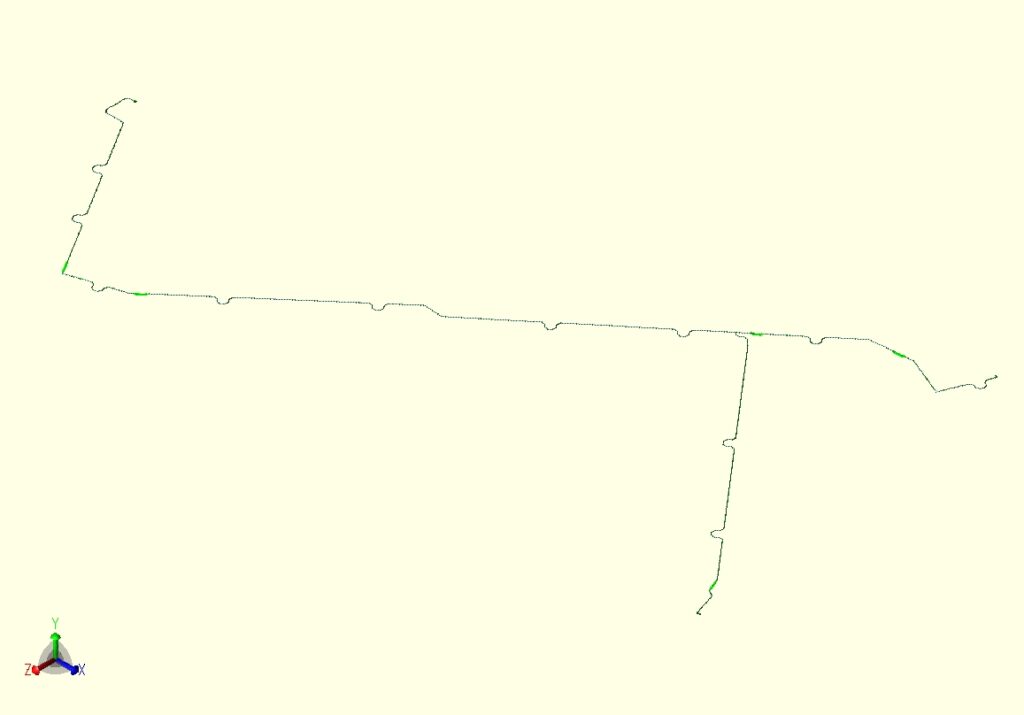
The following figure shows a typical pipeline as modeled using pipeline stress analysis software Caesar II
Pipeline Stress Analysis Basics
The basic equations for pipeline stress analysis are provided by the following codes and vary from one code to another. So readers are requested to refer to the following codes and standards for a better understanding of pipeline stress analysis basics.
- ASME B31.4 for liquid and slurry pipeline stress analysis
- ASME B31.8 for gas pipeline stress analysis
- ISO 14692 for pipelines made of GRE/GRP/FRP materials
- AWWA M 45 for big-size water pipelines.
Online Video Courses related to Pipeline Engineering
If you wish to explore more about pipeline engineering, you can opt for the following video courses
Hi, the last few weeks I’ve been working in some some stress analysis based on ASME B31.4. I noticed, as you said, to workd with this code is very different than work with ASME B31.3.
I really like your blog. I came it across while I was searching piping engineering books.
See you
Well explained blog. I appreciate it. Thank you
There are two ways to input the soil parameters in Caesar II, traditional method (Marston) and American Life alliance method. For the first one you need that soil study covers triaxial essay
Hi Anup Excellent site and very well explained topics. Just one comment on Stress Analysis based on ASME B31.4 post: Sustained Allowable was (0.75) (0.72) (Sy) = 0.54 Sy until the 2009 Edition. Since the 2012 Edition it was changed to 0.9 SY. Please refer to Table 403.3.1-1 for restrained pipeline SL.
Very useful topic, I still can’t find how expansion loops to be calculated or assumped?
In pipelines, loops are hardly used. Pipeline’s angle at bends (Intersection Points) are increased to provide flexibility.
We must check stresses in al thel cases when we are working on B31.4?
Why the expansion loops are hardly used in pipeline design?
Normally, Expansion loops are used in every 500 m of straight length.
Not in long length cross country pipelines.
Hi,
Why the pipeline buried sections with sleeves should be modeled as above-ground parts with spacer supports at even distances??
Hi, thanks for the explanation. Two questions:
1- if the distance between expansion loops to be considered 500m, line stop(intermediate anchors or end anchors) loads will be huge especially in seismic load cases. How do you deal with it?
2- What is the standard or guideline for the zig-gag configuration of expansion loops?
Hi,
If there will be short tutorial how to build model based on GA / alignment sheet, it will be better for engineer to start pipeline analysis job with confidence.