
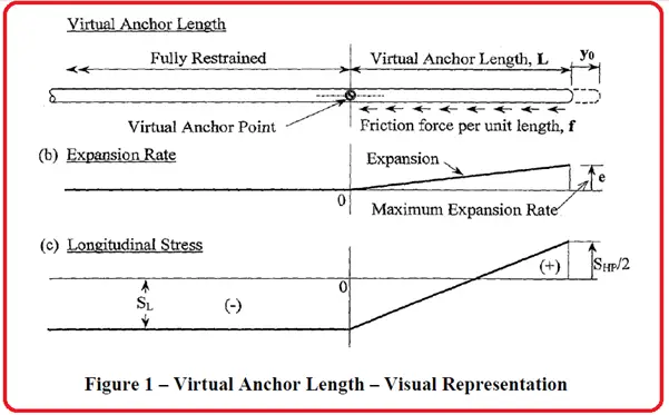
What is Virtual Anchor Length?
A pipeline restrained by fixed anchors will experience a series of stresses including longitudinal, bending, and axial. Virtual anchor lengths are taken as the distance required for the frictional force provided by the soil surrounding the pipe to equal the forces applied by thermal/ pressure expansion and the soil’s resisting friction per unit length of pipe.
Anchors are placed strategically along the pipeline to help prevent movement. Unrestrained pipeline movement can cause damage to the connecting piping and equipment. The length of piping required to form the virtual anchor is known as the active length. It must be noted that the force required to fully restrain a pipe is not a function of its length. Factors that influence the required force to restrain the pipe include temperature, pressure, and percentage strain within the pipe.
Soil provides a constant frictional force along a buried steel pipeline. The magnitude of the frictional force depends on the burial depth, pipe weight, soil density, and coefficient of friction between the soil and steel. Therefore, starting from a free end, the total restraint exerted by the soil on the pipe gradually increases until it reaches the fully restrained load at the virtual anchor. At this point, the naturally occurring forces are balanced with a restraint point. Similarly, moving along the pipe away from the virtual anchor, the pipe expansion becomes gradually minimized until a point of zero expansion is reached indicating the pipe is fully held in place.
Axial expansion is calculated by taking the average of the full axial restraint at one end of the pipe and zero restraint at the opposite end of the pipe. When compared to above-ground piping, the total axial expansion at the free end of a buried pipeline is half of the calculated value for a similar scenario involving the above-ground pipe.
In reality, most pipes do not have a totally free end but have some resistance due to soil restraint as the pipe exits the ground and from the connection to above-ground piping. This acts to reduce the expansion at the ‘free’ end. Soils with lower friction resistance or pipes with less depth of cover have longer active lengths and thus have greater expansion at the free end.
Virtual Anchor Length Calculation Sequence
Variables Required for Virtual Anchor Length Calculation
Pipe Properties
The following Pipe Parameters are required for Pipeline Virtual Anchor Length Calculation:
- Do = Outside Diameter of Pipe
- Di = Inside Diameter of Pipe
- D = Mean Diameter of Pipe = Do – TNom
- TNom = Nominal Wall Thickness of Pipe
- TAc = Actual Thickness of Pipe =TNom -CA
- v = Poisson’s Ratio
- a = Coefficient of Thermal Expansion
- ᵨP = Pipe Density
- CA = Corrosion Allowance
- E = Modulus of Elasticity of Pipe
- ᵨF = Pipe Fluid Density
- L = Length of Pipe
- A = Cross Section Area of pipe
- WP = Full Weight Pipe and its fluid.
Design & Other Conditions
- P = Design Pressure
- TD = Design Temperature
- TI = Installation Temperature
- D T = TD – TI
Required Soil Parameters
- µ = Coefficient of Friction between Pipe & Soil
- ᵨS = Soil Density
- H = Depth of Burial
Other Design Parameters
- Sh = Hoop Stress
- Sa = Axial Stress
- e = Strain
- FEx = Total Force Due to Expansion
- FEx(T) = Expansion Force Due to Temperature Change
- FEx(P) = Expansion Force Due to Pressure
- FP = Force due to Pressure
- FF = Frictional Force
- La = Anchor Length
Virtual Anchor Length Calculation
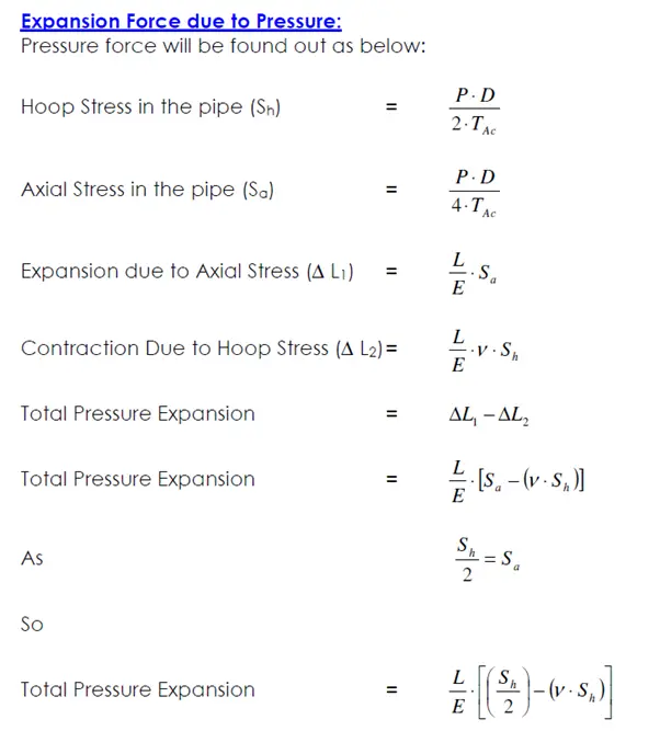
Theoretically, there will be pipe movement from the entry point due to thermal expansion. Also, an expansion will be there due to the pressure. Opposing these two is the frictional force between pipe and soil. Let us find these factors first:
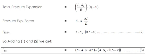
Expansion Force due to Temperature Change:
Expansion Force due to Change in Temperature will be:
FEx(T) = E × A×a × DT ………………………………..(1)
Few more Pipeline-related useful Resources for You.
Underground Piping Stress Analysis Procedure using Caesar II
Comparison between Piping and Pipeline Engineering
A Presentation on Pipelines – Material Selection in Oil & Gas Industry
Corrosion Protection for Offshore Pipelines
Start-up and Commissioning of the Pipeline: An Article
DESIGN OF CATHODIC PROTECTION FOR DUPLEX STAINLESS STEEL (DSS) PIPELINE
AN ARTICLE ON MICRO TUNNELING FOR PIPELINE INSTALLATION
A short presentation on OFFSHORE PIPELINE SYSTEMS: Part 1
Factors Affecting Line Sizing of Piping or Pipeline Systems
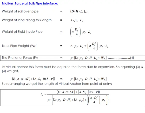
Hi! I don’t understand the resan of the multiplying factor “2” in formula number (4). Could you explain better? Thank.
Hello! I also cannot understand the reason of multiplying by “2” in formula number (4). In my opinion frictional force calculated by formula (4) shall be multiply by acceleration of gravity (g) because right now the units are not correct.
In my opinion in formula (4) the acceleration of gravity is missing!