Steam traps are very essential in power piping as these devices remove unnecessary condensate from the steam lines. A steam trap serves two basic purposes:
- Separate the condensate from the steam as quickly as it is generated and
- Stop the stream discharge.
Every steam systems normally employ many steam traps at strategic locations to avoid the condensate to mix with the steam and create a two-phase flow. The steam condensate two-phase flow can damage the piping, supports, or even the connected equipment if not removed. Thus steam traps play a major role in plant safety.
In this article, we will discuss the best practices for steam trap installation.
Steam trap Installation Best Practices
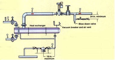
Studies have shown that incorrect steam trap installation creates a high percentage of steam trap failures. Certain faulty installation negatively impacts the steam trap performance. As per process heat transfer considerations, A properly installed steam trap needs
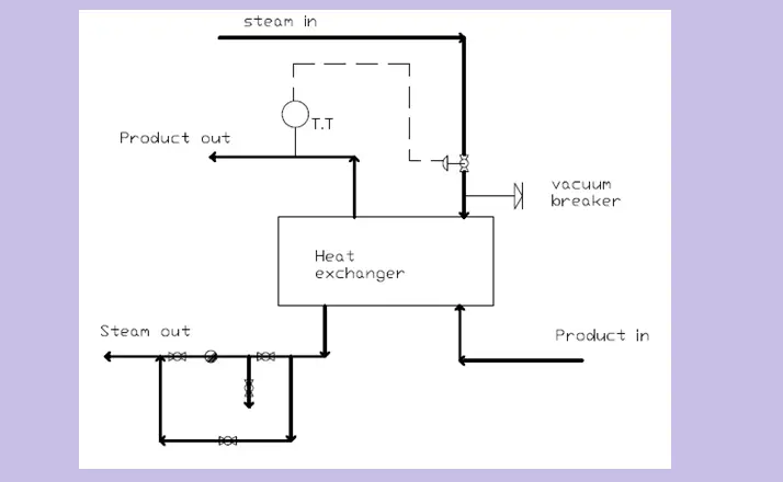
- a 24-in. minimum from the steam supply line to the steam-trap inlet and
- an 18-in. maximum from the vertical leg to the steam trap as shown in Fig. 1 below.
Experiences showed that a properly installed steam trap should efficiently work for six years without any maintenance.
A few of the Steam trap installation best practices are outlined below:
Ensure Gravity Flow:
The most important rule to remember for steam-trap installation is one of Mother Nature’s Laws — Gravity (Fig. 1). Installation should ensure the condensate flow from the process to the steam trap by the gravity forces. Pressure and velocity can not be relied on to remove the condensate from the process.
Ensure Steam Leakage Rate of Steam Traps:
For the Steam Traps that are being purchased, determine the steam leak rate following the leak rate standards mentioned below:
- a. PTC-39
- b. ISO 7841
A quantifiable amount of steam always leaks through the steam traps. Hence, The selected steam traps must ensure that steam traps with the least amount of steam loss are specified. Such Steam Traps will prevent unnecessary energy loss.
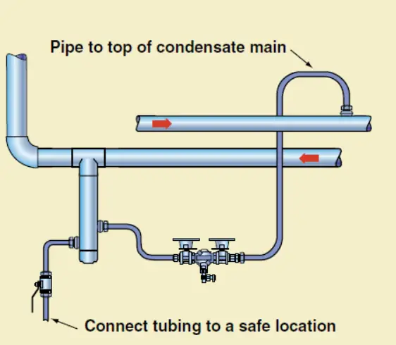
Threaded Connections:
Steam traps with 1 in. or smaller connections should use tubing with tube connectors. Such an arrangement will avoid leak points (for example, threaded connections). Traditionally, threaded connections are obvious sources of leaks in the system due to expansion, contraction, and corrosion that occurs in a steam system. Refer to Fig. 2.
Material Pressure rating:
Tube connections for steam trap installations are available from numerous steam-component manufacturers. Before placing an order ensure that the pressure ratings of the component material are acceptable.
The piping connection from Process to Steam Trap:
The Piping from the steam trap to the process connection shall be equal to or larger than the process outlet connection. Hence, it is suggested not to reduce the piping/tubing diameter before the steam trap or reduce the connection size of the steam trap. For example, a steam unit heater with a 1-in. condensate outlet would require 1-in. or larger piping/tubing from the unit heater to the same connection size on the steam trap.
Piping Connection Downstream of Steam Trap:
The pipe/tube diameter downstream of the discharge connection of the steam trap should be expanded. For example, 1-in. (connection) steam-trap discharge tubing/piping should be increased to 1.25 in. or 1.5 in.
Universal Mounts:
Universal mounts shall be used for connecting the steam trap devices with a connection size of 1 in. or smaller to the tubing or piping. With the universal mount, the steam trap is connected to the application with two bolts. This reduces the time required for the installation of the steam trap.
Use of Strainer:
Including a strainer as part of the steam trap installation is always suggested. The strainer can be accomplished by the following:
- a. External strainer ahead of the steam trap
- b. Steam trap with integral strainer
- c. Universal mount with an integral strainer
Premature Steam trap failures due to corrosion will be eliminated by the strainer.
When installing an external or internal strainer, always install a blow-off valve on the strainer. This allows the strainer to be blown down during operation and, more importantly, permits the steam trap cavity to be safely depressurized during service.
Some other important Steam trap Installation Best Practices are:
- The steam trap should be installed in an accessible location.
- A visual indication (can be a sight glass or test valve) of the steam trap performance shall be installed on all process applications.
- Always locate the steam trap below the lowest condensate discharge point of the equipment.
- Ahead of the steam trap, A rise in pipe elevation is not at all desirable.
- In most applications, check valves are installed after the steam traps.
- Installation standards for all applications shall be maintained for future reference.
- ASME B31.1 code is normally followed.